CWBW Shipboard Decon Procedures and Collective Protective System
")
CW/BW Shipboard Decon Procedures and Collective Protective System (CPS)

Enabling Objectives ¶ Perform buddy aid and self aid procedures · Perform the procedures to detect and classify chemical agent stimulants ¸ Discuss decon procedures on gloves, mask, face and mask interior using M 291 ¹ Describe the procedures to isolate and mark chemical and biological contaminated areas º Describe the methods used to decon chemically and biologically contaminated exterior and interior shipboard surfaces
 in")
Enabling Objectives n. State the functional description of the Collective Protection System (CPS) in accordance with SS 200 -AF-MMM-010 Navy Shipboard Collective Protection System (CPS) System, Description, Operation, and Maintenance to include component characteristics.

Isolating & Marking Contaminated Areas n Biological n agent contamination Rope area off contaminated area n Marking 8 X 11 1/2 inch triangular-shaped sign n Blue background n "Bio" inscribed in red n

Bio Marking n Info required on marker Agent n Date n Time n n Attach BIO marker so letters of marker face away from contaminated area

Chemical marking n Chemical n agent contamination Rope off area 11. 5” n Marking Yellow background n "Gas" inscribed in red n n Information Agent n Date n Time n GAS 8” required on sign 8”

11. 5” ATOM 8” 8”

Chemical & Biological Agent Decontamination n Methods of decon Weathering Effects n Low humidity - causes microorganisms to dry out n Rain washes microorganisms off objects n Sunlight will kill most biological agents within a day n

Chemical & Biological Agent Decontamination n Physical removal Countermeasure Wash Down System n Prevents agents adhering to surfaces n n Estimations of removal No pre-wetting/no washdown, 0% removal n No pre-wetting/15 minute washdown, 60% of V series and 90% of H&G series agents n Intermittent pre-wetting/15 minute washdown, 95% of all agents removed n

Chemical & Biological Agent Decontamination n Fire n hosing Used after CMWDS n Scrubbing n Decon solutions enhance scrubbing n Steaming n Raising the temp to an average of 212 degrees, effectively destroys most microorganism
 Universal decontaminate, destroys all CW and BW agents")
Decontaminating solutions n Calcium Hypochlorite (HTH) Universal decontaminate, destroys all CW and BW agents n Highly corrosive n WILL BURN SKIN & EYES AND PRODUCE A TOXIC VAPOR NOT TO BE USED FOR DECONTAMINATING AIRCRAFT OR SENSITIVE EQUIPMENT

Decontaminating solutions n Detergent Synthetic organic detergent/ white flaky solid n When unavailable, liquid detergent #50 or equivalent may be substituted n NEVER MIX HTH & DETERGENT TOGETHER

Levels of decontamination n Operationally complete decontamination decon that will allow completion of ships mission n Done by ships force n n Complete decontamination decon that the appropriate tests fail to give a positive response n Naval Shipyards, advanced bases, or by shore based personnel n

Areas most heavily contaminated n CW agents All decks & horizontal surfaces n Vertical surfaces facing wind n Painted surfaces may absorb CW agents n n BW agents Small diameter cylinders such as lines, halyards, ropes & handles n All surfaces close to edges, corners, and protruding fittings n

Decontamination procedures n Exterior surfaces Countermeasure wash down system n Decon teams n Work top to bottom, windward to leeward n Fire hosing & scrubbing n 1% hypochlorite/detergent solution n Heavily contaminated use 9% n

Decontamination procedures Vertical surfaces, scrub top to bottom n Horizontal surfaces, scrub one direction n Retest area for contamination n n Interior solution spaces using HTH/decon Push contamination toward center of the contaminated area n Mop up contaminated water with cloth or paper & dispose of in containers n

Decontamination procedures n Aircraft & sensitive equipment Light-duty or medium-duty cleaners n Applied by a gentle spray or mopped & scrubbed n Flushing with gentle streams of water should be applied to openings in or around sensitive equipment n
")
Collective Protective System (CPS)
 in accordance")
Enabling Objectives STATE the functional description of the Collective Protection System (CPS) in accordance with SS 200 -AF-MMM-010 Navy Shipboard Collective Protection System (CPS) System, Description, Operation, and Maintenance to include: n Component characteristics. n Component functions. n .

Purpose The anticipated use of CBR weapons against Navy ships has reinforced the need to provide a better counter-measure defense from toxic CBR fallout.
 – provides filtered air to designated zones to protect")
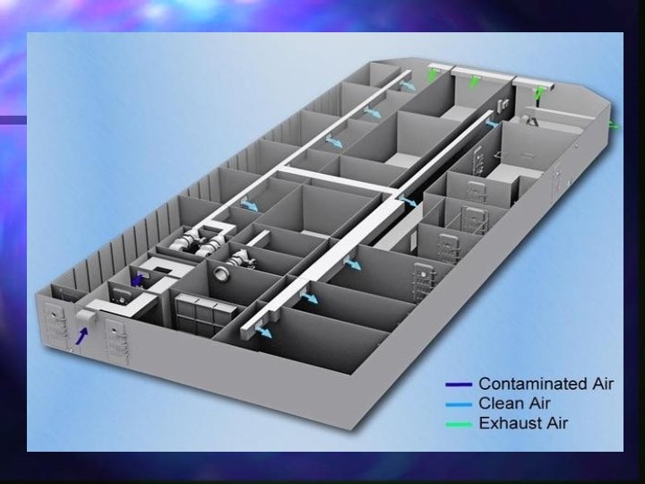
Purpose Collective Protection System (CPS) – provides filtered air to designated zones to protect personnel against CBR contamination onboard ship. CPS is designed to be a continuously operating system.

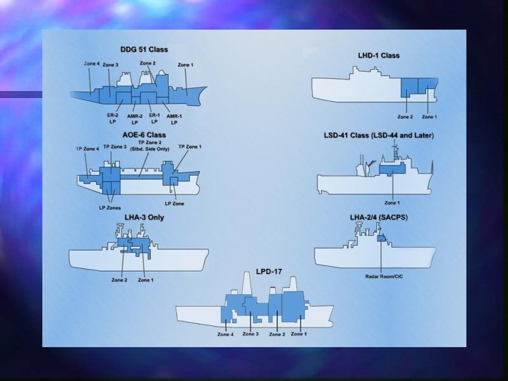
Component Functions n Zones Characteristics and – CPS - an protection area within system that against CBR a collective provides agents. Total Protection (TP) Zone n Limited Protection (LP) Zone n
: DDG 4 ZONES n DDG FLT 2 A 3 ZONES n")
Total Protection (TP): DDG 4 ZONES n DDG FLT 2 A 3 ZONES n LHD 2 ZONES n LHD WITH BACKFIT 6 ZONES n LSD 2 ZONES n AOE 4 ZONES n
: Provides a toxic free environment by filtering the supply air")
Total Protection (TP): Provides a toxic free environment by filtering the supply air and maintaining an overpressure in the zone to prevent contaminants from leaking inside. n Total protection against liquid, solid, and gaseous agents vapors. n Provides a toxic free environment where it is not necessary to wear protective clothing or masks. n
: The three TP zones will vary due to the ship design,")
Total Protection (TP): The three TP zones will vary due to the ship design, the factors are command control and personnel: Level one is the shelter envelope, safe haven Level two is the minimum operational envelope, surprise attack survival. Level three is the maximum operational envelope, sufficient TP coverage.
 ZONE Engineering Spaces • Provides protection against CBR contaminants in a")
LIMITED PROTECTION (LP) ZONE Engineering Spaces • Provides protection against CBR contaminants in a solid or liquid form only, does not provide protection against vapors • Not Pressurized, Personnel are required to wear protective masks during a CBR attack • Full personnel protective ensembles are not required unless there is evidence of high concentrations of vapors that are percutaneous (skin) hazards

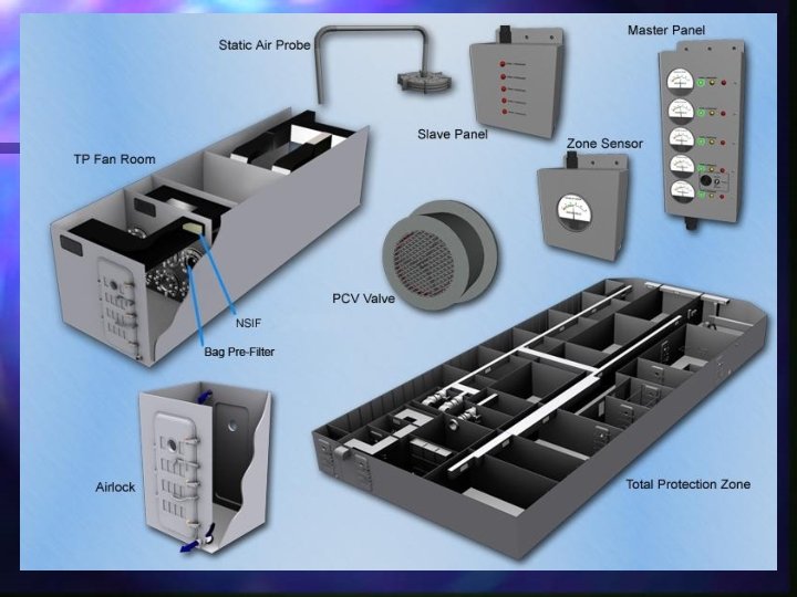
Zone Components:

TP Zone Components: n Weather Air Intake/Airlift – where the air enters the supply system from the outside atmosphere.
: Protects the CBR filters from the damaging")
TP Zone Components: Anti-Blast Valve (when installed): Protects the CBR filters from the damaging pressures generated by conventional or nuclear detonations. n Instantaneously close in response to the shock front and reopen once the shock wave has passed. n Installations are a function of ships survivability requirements. n
 roughing filter Stock # 5: n")
TP Zone Components: Navy Standard Impingement Filter (NSIF) roughing filter Stock # 5: n Installed in the weather air intake/airlift immediately downstream of the anti-blast valve. n Uses a metal mesh medium (aluminum/stainless) to prevent large particles from entering the inlet plenum. n

TP Zone Components: n Preheater - (if installed, raise the temperature to above 42. Ships tech. Manual should specify the type and features. Recommend electric. n Humidistats - activate the preheaters when the intake air has greater than 75% relative humidity.

TP Zone Components: Inlet Plenum - a space between the air intake and filter housing for access to the filters. n Filter Casing - provides a structure for mounting the filter module(s). n Filter Module - provides support and an enclosure for the CBR filter set. n

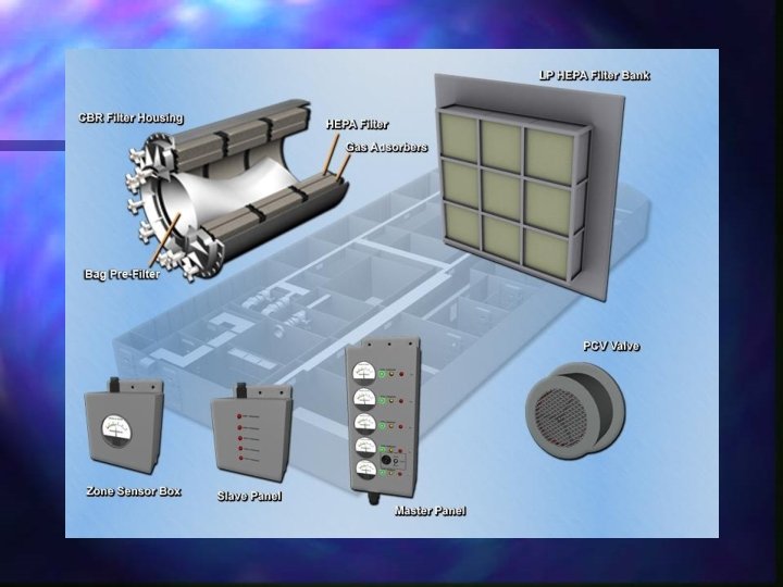
TP Zone Components: n Prefilter: Either one bag prefilter or three cylindrical prefilters are installed inside each CBR filter housing. Captures coarse particles to reduce loading on the CBR HEPA filter to greatly extend CBR filter life.

TP Zone Components: CBR filter Sets consist of a HEPA and a gas adsorbent: n Highly Efficient Particulate arresting (HEPA) filter a two stage, pleated-medium filter for removing solid and aerosol CBR contaminants. Has a rated flow capacity of 200 cubic feet per minute (cfm). n Gas Adsorbent Filter contains activated charcoal for removing chemical warfare gases. n

TP Zone Components: n Outlet Plenum - space between the filter casing and the supply system cannot be used for storage. n High Pressure Centrifugal Supply Fans with Navy Standard Dampers. n Cooling Coils (if equipped) - Navy standard air conditioning coils.
 CBR Filter Systems - supply air to TP")
TP Zone Components: Compressed Air (LPAC/HPAC) CBR Filter Systems - supply air to TP and LP zones is filtered of solid, liquid, and gaseous CBR contaminants. n TP Zone - filtered air maintained at 2. 0 inches of water gauge (in. WG) over pressure. 5 or above depending on ship’s system or if part of back-fit program. Ship must refer to CPS logs for exact pressure required. n
: Two or more located at")
Sources of Air Loss n Pressure Control Valves (PCV): Two or more located at zone boundaries. Used to relieve excess air pressure and preventing air from being forced through drain traps.

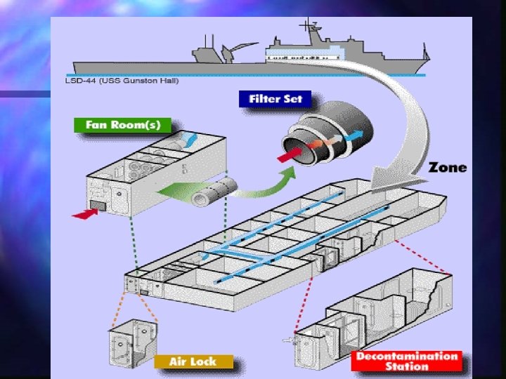
Sources of Air Loss Air locks – Located at zone boundaries, allows personnel to transit into or out of the zone without reducing zone pressure: Contains two doors that must be opened separately to maintain zone pressure. Utilizes air sweeps to purge any airborne contaminants.

Three types of air locks: n Type I - leads from pressurized area directly to weather, air is swept continuously from top to bottom and across air lock, in a contaminated environment can only be used to exit the ship. n Type II - leads from a pressurized zone to an unpressurized internal area of ship, air is swept continuously from top to bottom and across the air lock.

Air Locks Type III - used to connect two pressure zones, used as a damage control feature should pressure be lost in one zone, have fittings to allow purging in either direction, fittings are normally closed, when fittings are opened air lock can be used as a type II air lock.

WARNING ALWAYS USE CAUTION AND OPEN ONLY ONE DOOR AT A TIME WHILE USING AIRLOCKS AND PRESSURE LOCKS. FAILURE TO DO SO COULD CAUSE PERSONNEL INJURY (FROM SLAMMING DOORS OR FOREIGN PARTICLES IN EYES) AND LOSS OF ZONE PRESSURE.

Air Locks n After a allowed minutes n NOTE: CBR attack, air lock must be to purge for approximately 2 before it can be used again. Purge time depends on size of air lock and ships pressure at the time of purging.

Air Locks n Outfitted with a safety latch which acts as a safety catch. It also prevents an improperly opened boundary door from flying open when the zone is pressurized.

Pressure locks: n Similar to air locks but do not have air sweeps. Provide access to and from a TP zone to other areas of the ship only in an uncontaminated environment. n -Must not be used after a CBR attack. n -Outfitted with safety latch.

Sources of Air loss Cont. n Exhaust Fans - one or more centrifugal exhaust fans with three position dampers used to remove air from the zone. n Pre-positioned dampeners.

CPS Control Units n Master Panel n Slave Panel n Zone Sensor box and Pressure Gauge

CPS Control Units Master Panel – located in DCC or CCS, is the main alarm panel for monitoring each TP zone. Is divided into 3 color codes RED LOW YELLOW DEFICIENT GREEN NORMAL

CPS Control Units Slave Panel - located in the pilothouse the red indicator lamp is provided for each TP zone, warns when pressure in any zone falls below 0. 4 in. wg SHOULD BE UNLIT

CPS Control Units Zone Sensor Box – located in each TP zone to measure the overpressure in that zone. A static air probe is mounted outside the TP Zone in an area where it is subject to ambient air pressure. n The Probe - connected through a network of tubing to each zone sensor box, reduces the effects if wind on static pressure and provides true zone pressure. n

Summary and Review n n n n Isolating & marking contaminated areas Chemical & Biological decontamination Decontamination of exterior, interior spaces, aircraft and sensitive equipment What is the purpose of CPS? List CPS Components: What are the ranges of your gauge readings? What are the 3 types of Air locks?
- Slides: 55