
Customer Technical Training CARRIER COMFORT NETWORK BUS ARCHITECTURE

Customer Technical Training CARRIER COMFORT NETWORK BUS ARCHITECTURE 6/28/98 CCN_BUS 1

Customer Technical Training Carrier Comfort Network • Carrier Comfort Network (CCN) is a controls concept that consist of Carrier control products and Carrier equipment that are stand alone as well as designed to function together on a Digital Control System. 6/28/98 CCN_BUS 2

Customer Technical Training CCN BUS ARCHITECTURE CCN PRIMARY BUS (3 Conductor Shielded stranded wire cable 18 ga. ) TEMP VVT (CCS) Comfort Controllers PIC CIO (CCN) Or FID’s (CCN) • For General CCN Type Devices: Theoretical Maximum of 239 Devices on any bus. • For CCS type Devices: A Maximum of 32 33 CS Devices or 8 Scanning Devices (Monitor Stat’s) on any bus. • This is a Local Area Network (LAN) not a Wide Area Network (WAN) 6/28/98 CCN_BUS 5
Customer Technical Training CCN BUS ARCHITECTURE PIC’s Product Integrated Control • Is Factory Mounted On Carrier HVAC Equipment With Sensors – VAV Air Terminals – Air Handling Units – Chillers – Rooftop Units 6/28/98 CCN_BUS 6
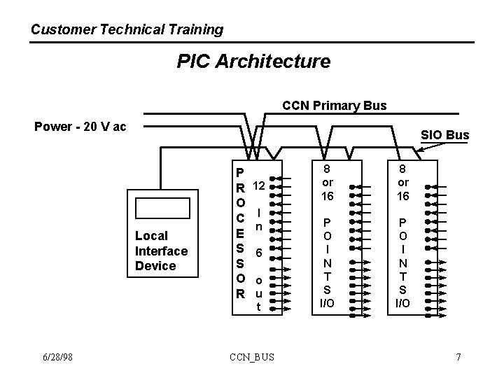
Customer Technical Training PIC Architecture CCN Primary Bus Power - 20 V ac SIO Bus Local Interface Device 6/28/98 P R O C E S S O R 12 I n 6 o u t CCN_BUS 8 or 16 P O I N T S I/O 7
Customer Technical Training CCN BUS ARCHITECTURE FID ’s Field Installed Device • Is An All Purpose Controller For Carrier Equipment without PIC’s & Non- Carrier HVAC Equipment • In Addition Controls 6/28/98 – Cooling Towers – Pumps – Lights CCN_BUS – Boilers 8
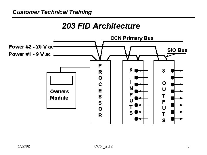
Customer Technical Training 203 FID Architecture CCN Primary Bus Power #2 - 20 V ac Power #1 - 9 V ac Owners Module 6/28/98 SIO Bus P R O C E S S O R CCN_BUS 8 8 I N P U T S O U T P U T S 9
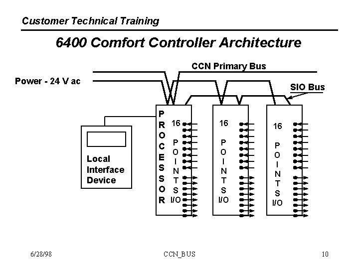
Customer Technical Training 6400 Comfort Controller Architecture CCN Primary Bus Power - 24 V ac SIO Bus Local Interface Device 6/28/98 P R O C E S S O R 16 16 16 P O I N T S I/O CCN_BUS 10
Customer Technical Training CIO ’s ARCHITECTURE Communications Input / Output • For System Level Control Strategies – Chiller Plant Control – VAV Air Systems Control – Loadshed – Watersource Heatpump Systems – PTAC System Management 6/28/98 CCN_BUS 11
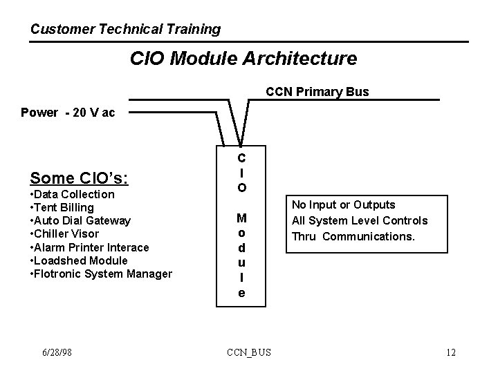
Customer Technical Training CIO Module Architecture CCN Primary Bus Power - 20 V ac Some CIO’s: • Data Collection • Tent Billing • Auto Dial Gateway • Chiller Visor • Alarm Printer Interace • Loadshed Module • Flotronic System Manager 6/28/98 C I O M o d u l e CCN_BUS No Input or Outputs All System Level Controls Thru Communications. 12
Customer Technical Training CCN BUS ARCHITECTURE The Key to the CCN BUS is Addressing: • An address is required of all devices on the bus. • No two devices on the same CCN system may ever have the same address. • A CCN and CCS address consists of a 3 digit bus number and a 3 digit device number. 6/28/98 CCN_BUS 13
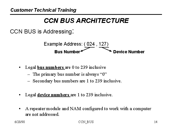
Customer Technical Training CCN BUS ARCHITECTURE CCN BUS is Addressing: Example Address: ( 024 , 127) Bus Number Device Number • Legal bus numbers are 0 to 239 inclusive – The primary bus number is always “ 0” – Secondary bus numbers are 1 to 239 inclusive. • Legal device numbers are 1 to 239 inclusive. • A repeater module and NAM configured to work with a computer are not addressed. 6/28/98 CCN_BUS 14
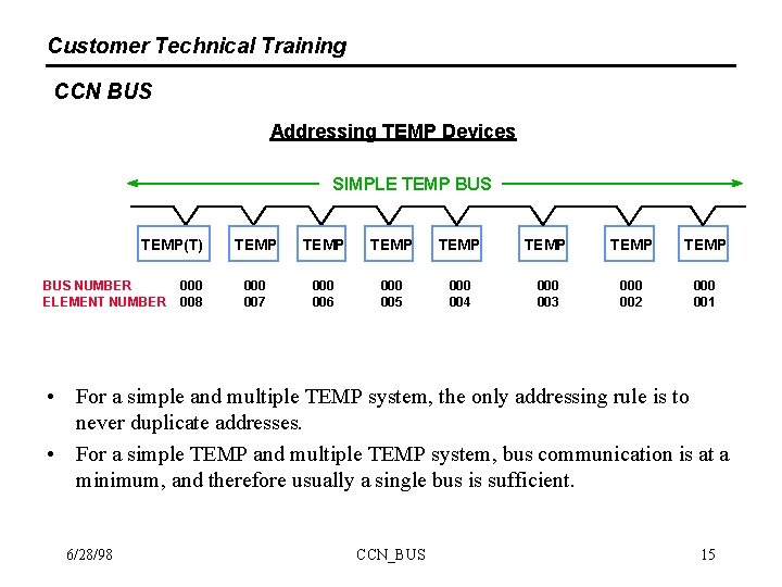
Customer Technical Training CCN BUS Addressing TEMP Devices SIMPLE TEMP BUS TEMP(T) BUS NUMBER ELEMENT NUMBER 000 008 TEMP TEMP 000 007 000 006 000 005 000 004 000 003 000 002 000 001 • For a simple and multiple TEMP system, the only addressing rule is to never duplicate addresses. • For a simple TEMP and multiple TEMP system, bus communication is at a minimum, and therefore usually a single bus is sufficient. 6/28/98 CCN_BUS 15
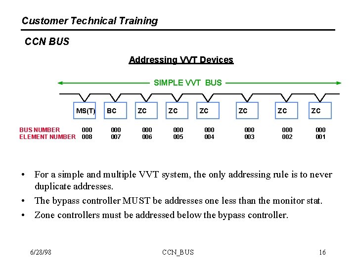
Customer Technical Training CCN BUS Addressing VVT Devices SIMPLE VVT BUS MS(T) BUS NUMBER ELEMENT NUMBER 000 008 BC 000 007 ZC 000 006 ZC 000 005 ZC 000 004 ZC 000 003 ZC 000 002 ZC 000 001 • For a simple and multiple VVT system, the only addressing rule is to never duplicate addresses. • The bypass controller MUST be addresses one less than the monitor stat. • Zone controllers must be addressed below the bypass controller. 6/28/98 CCN_BUS 16
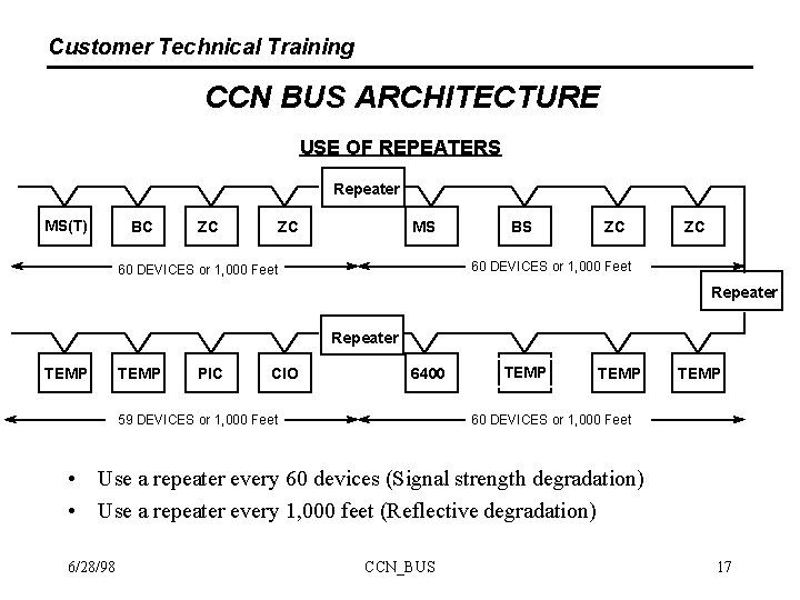
Customer Technical Training CCN BUS ARCHITECTURE USE OF REPEATERS Repeater MS(T) BC ZC ZC MS BS ZC ZC 60 DEVICES or 1, 000 Feet Repeater TEMP PIC CIO 6400 59 DEVICES or 1, 000 Feet TEMP 60 DEVICES or 1, 000 Feet • Use a repeater every 60 devices (Signal strength degradation) • Use a repeater every 1, 000 feet (Reflective degradation) 6/28/98 CCN_BUS 17
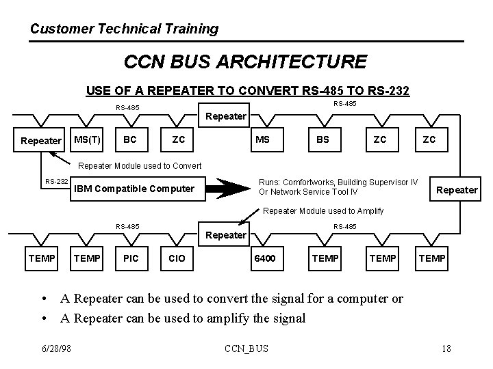
Customer Technical Training CCN BUS ARCHITECTURE USE OF A REPEATER TO CONVERT RS-485 TO RS-232 RS-485 Repeater MS(T) BC Repeater ZC MS BS ZC ZC Repeater Module used to Convert RS-232 Runs: Comfortworks, Building Supervisor IV Or Network Service Tool IV IBM Compatible Computer Repeater Module used to Amplify RS-485 TEMP PIC RS-485 Repeater CIO 6400 TEMP • A Repeater can be used to convert the signal for a computer or • A Repeater can be used to amplify the signal 6/28/98 CCN_BUS 18
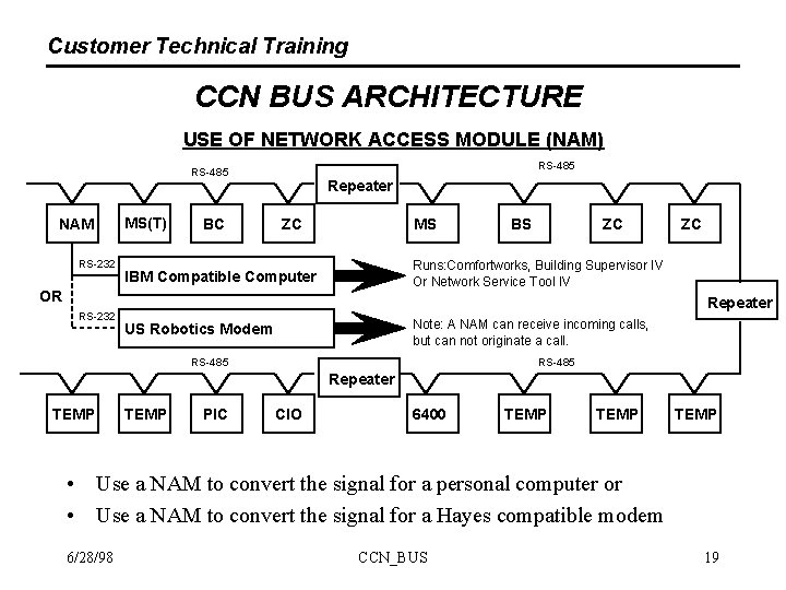
Customer Technical Training CCN BUS ARCHITECTURE USE OF NETWORK ACCESS MODULE (NAM) RS-485 NAM RS-232 MS(T) BC Repeater ZC MS ZC ZC Runs: Comfortworks, Building Supervisor IV Or Network Service Tool IV IBM Compatible Computer OR RS-232 BS Repeater Note: A NAM can receive incoming calls, but can not originate a call. US Robotics Modem RS-485 Repeater TEMP PIC CIO 6400 TEMP • Use a NAM to convert the signal for a personal computer or • Use a NAM to convert the signal for a Hayes compatible modem 6/28/98 CCN_BUS 19
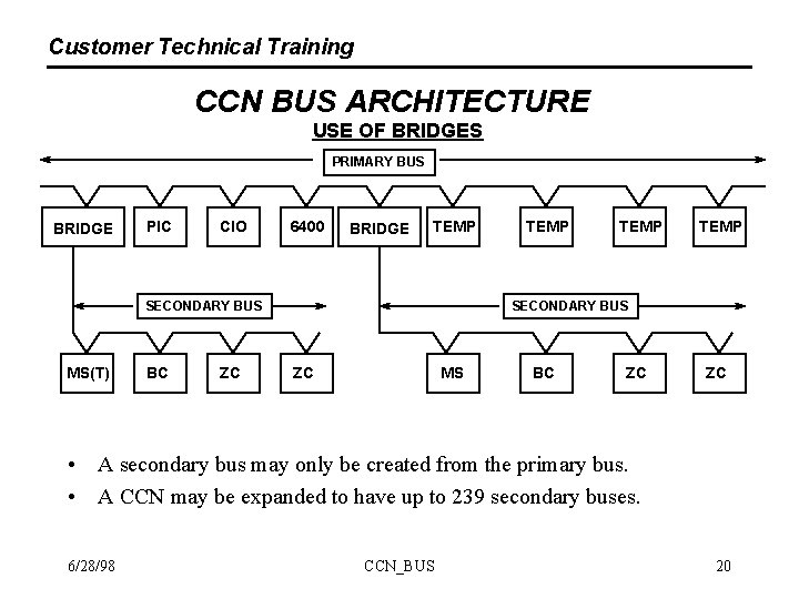
Customer Technical Training CCN BUS ARCHITECTURE USE OF BRIDGES PRIMARY BUS BRIDGE PIC CIO 6400 BRIDGE TEMP SECONDARY BUS MS(T) BC ZC TEMP SECONDARY BUS ZC MS BC ZC ZC • A secondary bus may only be created from the primary bus. • A CCN may be expanded to have up to 239 secondary buses. 6/28/98 CCN_BUS 20
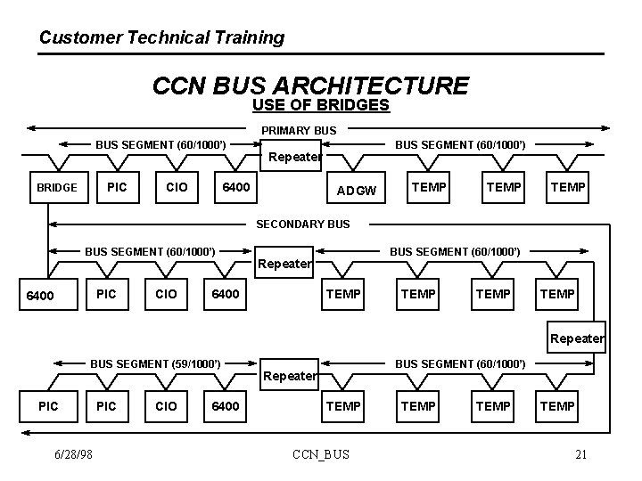
Customer Technical Training CCN BUS ARCHITECTURE USE OF BRIDGES PRIMARY BUS SEGMENT (60/1000’) PIC BRIDGE CIO BUS SEGMENT (60/1000’) Repeater 6400 ADGW TEMP SECONDARY BUS SEGMENT (60/1000’) PIC 6400 CIO BUS SEGMENT (60/1000’) Repeater 6400 TEMP Repeater BUS SEGMENT (59/1000’) PIC 6/28/98 PIC CIO 6400 BUS SEGMENT (60/1000’) Repeater TEMP CCN_BUS TEMP 21
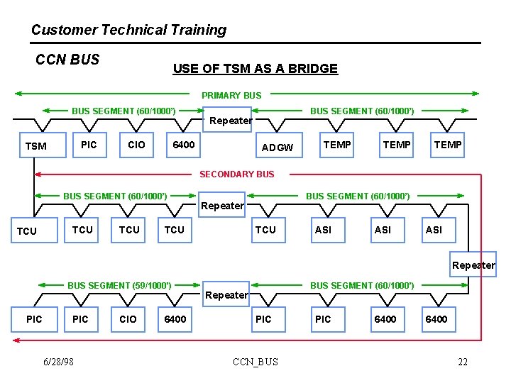
Customer Technical Training CCN BUS USE OF TSM AS A BRIDGE PRIMARY BUS SEGMENT (60/1000’) PIC TSM CIO BUS SEGMENT (60/1000’) Repeater 6400 ADGW TEMP SECONDARY BUS SEGMENT (60/1000’) TCU TCU BUS SEGMENT (60/1000’) Repeater TCU ASI ASI Repeater BUS SEGMENT (59/1000’) PIC 6/28/98 CIO 6400 BUS SEGMENT (60/1000’) Repeater PIC CCN_BUS PIC 6400 22
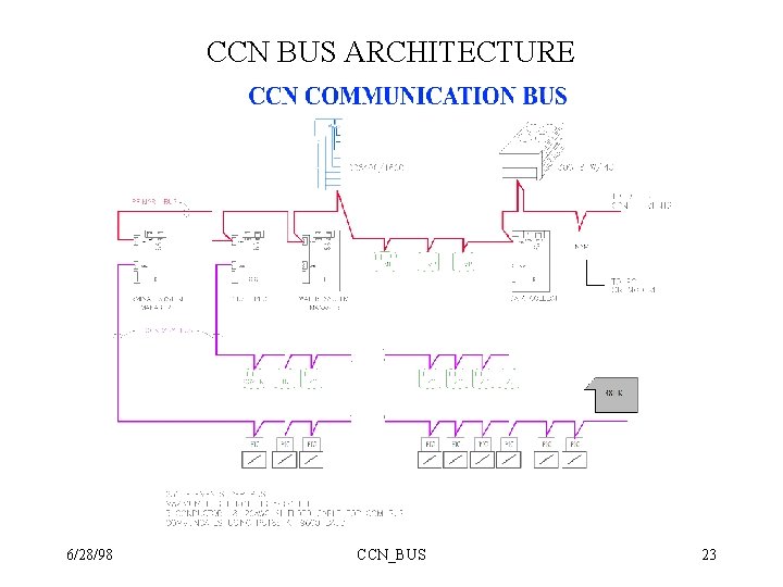
CCN BUS ARCHITECTURE 6/28/98 CCN_BUS 23
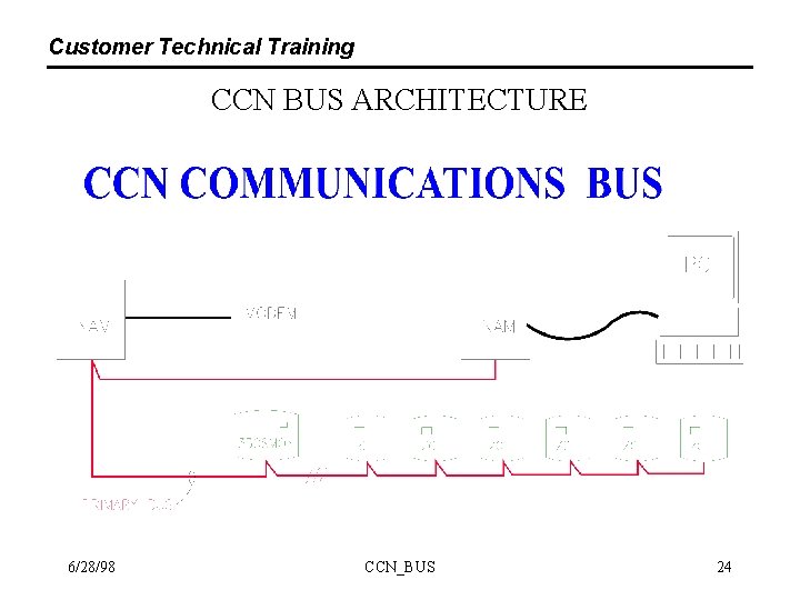
Customer Technical Training CCN BUS ARCHITECTURE 6/28/98 CCN_BUS 24
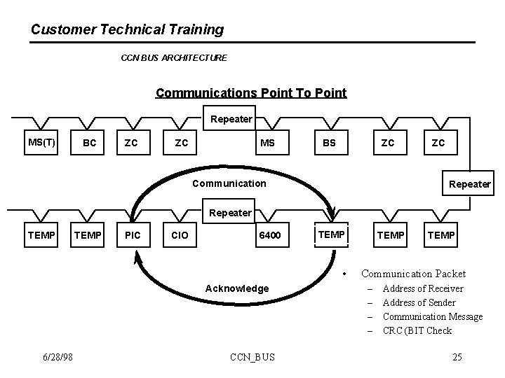
Customer Technical Training CCN BUS ARCHITECTURE Communications Point To Point Repeater MS(T) BC ZC ZC MS BS ZC Communication ZC Repeater TEMP PIC CIO 6400 TEMP • Acknowledge 6/28/98 CCN_BUS TEMP Communication Packet – – Address of Receiver Address of Sender Communication Message CRC (BIT Check 25
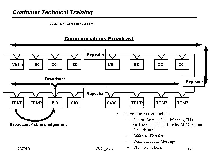
Customer Technical Training CCN BUS ARCHITECTURE Communications Broadcast Repeater MS(T) BC ZC ZC MS BS ZC Broadcast ZC Repeater TEMP PIC CIO TEMP 6400 • Broadcast Acknowledgement CCN_BUS TEMP Communication Packet – 6/28/98 TEMP – – – Special Address Code Meaning This package is to be received by All Nodes on the Network Address of Sender Communication Message CRC (BIT Check 26
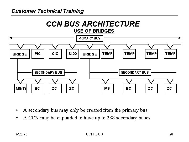
Customer Technical Training CCN BUS ARCHITECTURE USE OF BRIDGES PRIMARY BUS BRIDGE PIC CIO 6400 BRIDGE TEMP SECONDARY BUS MS(T) BC ZC TEMP SECONDARY BUS ZC MS BC ZC ZC • A secondary bus may only be created from the primary bus. • A CCN may be expanded to have up to 238 secondary buses. 6/28/98 CCN_BUS 28
- Slides: 25