
CTF 3 LowLevel RF measurements TBTSTBS lines and
CTF 3 Low-Level RF measurements TBTS/TBS lines and 12 GHz testand (Xbox 1) Stéphane Rey* - BE/RF Luca Timeo - BE/RF Ben Woolley - BE/RF Wilfrid Farabolini - CEA October 7 th, 2013 - Rev 1. 0
Calibrating RF measurement paths Why ? � � To ensure each device is rated for the frequency and power applied To get best measurement accuracy of RF powers � � � To measure RF path characteristics (insertion & return losses, linearity, reflections, …) To check and compensate long term drifts To provide RF systems diagnosis How ? Several methods : � Method 1 : Generator + powermeter S 21 � Method 2 : Generator + 4 powermeters S 11, S 22, S 12 � Method 3 : VNA 1 -port S 11, � Method 4 : VNA 2 -ports S 11, S 22, S 12 � Method 5 : TDR (Time Domain Reflectometry) using a VNA S 11 + postprocessing (inverted FFT x virtual pulse) S 11, S 22 � Method 6 : TDR using a Time Domain Reflectometer S 11, S 22 � Method 7 : TWT + CTF 3 Acquisition system and powermeters S 21, S 11, S 22 CTF 3 LLRF measurement - S. Rey / L. Timeo / B. Woolley / W. Farabolini – October 2013 – Rev 1. 0 2
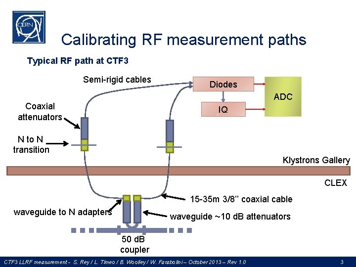
Calibrating RF measurement paths Typical RF path at CTF 3 Semi-rigid cables Diodes ADC Coaxial attenuators IQ N to N transition Klystrons Gallery CLEX 15 -35 m 3/8’’ coaxial cable waveguide to N adapters waveguide ~10 d. B attenuators 50 d. B coupler CTF 3 LLRF measurement - S. Rey / L. Timeo / B. Woolley / W. Farabolini – October 2013 – Rev 1. 0 3
The true life (or Murphy law variation) � � � � Different measurement methods gives different results Measurement instruments are less accurate than the expected measured accuracy Devices are never specified correctly… if they are specified ! … and are anyway never used within their nominal specified range RF Powers are always above expectations ‘Low-phase’ coaxial cables are phase dependent Fixed attenuators are not A 5 watts rated equipment exhibits a derating starting from 1 watt and burns at 4 watts Symmetric devices are not ‘Perfectly matched’ devices have a return loss > -10 d. B … which fluctuates over time Controlled temperature means ‘almost controlled’ Screwing a connector again with the same torque never gives the same return loss ‘Do not touch’ warning signs are usually inviting people to touch CTF 3 LLRF measurement - S. Rey / L. Timeo / B. Woolley / W. Farabolini – October 2013 – Rev 1. 0 4

Instruments accuracy (or uncertainty) Multimeter Agilent 34401 A – 6½ digits (source 34401 A datasheet) Powermeter Agilent E 4416 (source E 4416 datasheet) � Absolute accuracy = ± 0. 04 d. B within ± 5°C from its calibration temperature � Absolute accuracy = ± 0. 08 d. B from 0 to 55°C CTF 3 LLRF measurement - S. Rey / L. Timeo / B. Woolley / W. Farabolini – October 2013 – Rev 1. 0 5
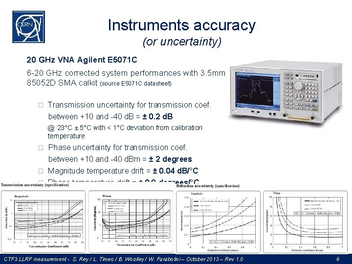
Instruments accuracy (or uncertainty) 20 GHz VNA Agilent E 5071 C 6 -20 GHz corrected system performances with 3. 5 mm 85052 D SMA calkit (source E 5071 C datasheet) � Transmission uncertainty for transmission coef. between +10 and -40 d. B = ± 0. 2 d. B @ 23°C ± 5°C with < 1°C deviation from calibration temperature � Phase uncertainty for transmission coef. between +10 and -40 d. Bm = ± 2 degrees � Magnitude temperature drift = ± 0. 04 d. B/°C � Phase temperature drift = ± 0. 8 degrees/°C CTF 3 LLRF measurement - S. Rey / L. Timeo / B. Woolley / W. Farabolini – October 2013 – Rev 1. 0 6
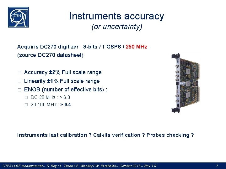
Instruments accuracy (or uncertainty) Acquiris DC 270 digitizer : 8 -bits / 1 GSPS / 250 MHz (source DC 270 datasheet) � Accuracy ± 2% Full scale range � Linearity ± 1% Full scale range � ENOB (number of effective bits) : � DC-20 MHz : > 6. 8 � 20 -100 MHz : > 6. 4 Instruments last calibration ? Calkits verification ? Probes checking ? CTF 3 LLRF measurement - S. Rey / L. Timeo / B. Woolley / W. Farabolini – October 2013 – Rev 1. 0 7
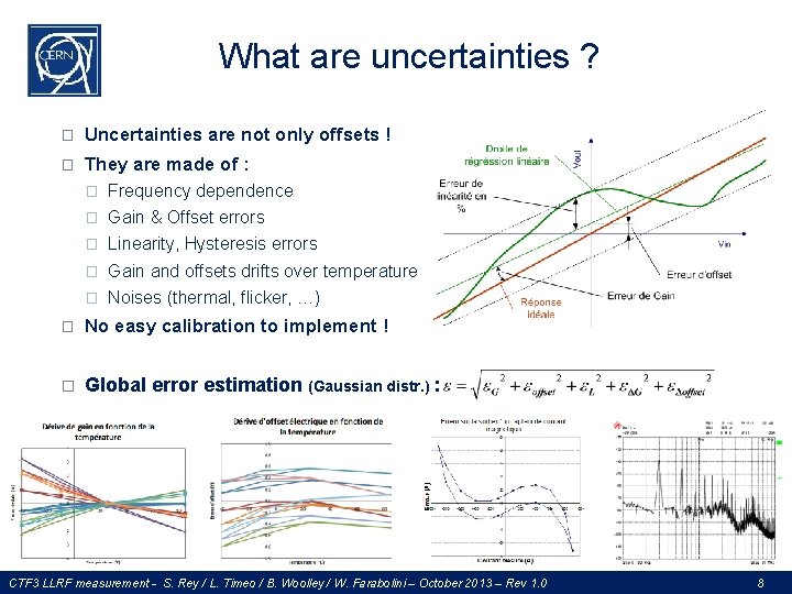
What are uncertainties ? � Uncertainties are not only offsets ! � They are made of : � Frequency dependence � Gain & Offset errors � Linearity, Hysteresis errors � Gain and offsets drifts over temperature � Noises (thermal, flicker, …) � No easy calibration to implement ! � Global error estimation (Gaussian distr. ) : CTF 3 LLRF measurement - S. Rey / L. Timeo / B. Woolley / W. Farabolini – October 2013 – Rev 1. 0 8
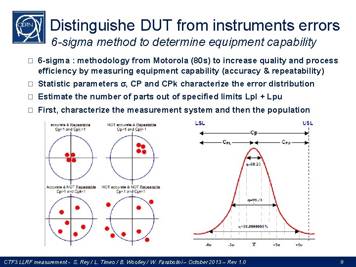
Distinguishe DUT from instruments errors 6 -sigma method to determine equipment capability � 6 -sigma : methodology from Motorola (80 s) to increase quality and process efficiency by measuring equipment capability (accuracy & repeatability) � Statistic parameters , CP and CPk characterize the error distribution � Estimate the number of parts out of specified limits Lpl + Lpu � First, characterize the measurement system and then the population CTF 3 LLRF measurement - S. Rey / L. Timeo / B. Woolley / W. Farabolini – October 2013 – Rev 1. 0 9
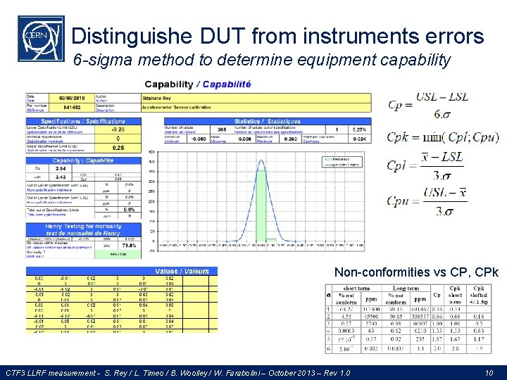
Distinguishe DUT from instruments errors 6 -sigma method to determine equipment capability Non-conformities vs CP, CPk CTF 3 LLRF measurement - S. Rey / L. Timeo / B. Woolley / W. Farabolini – October 2013 – Rev 1. 0 10
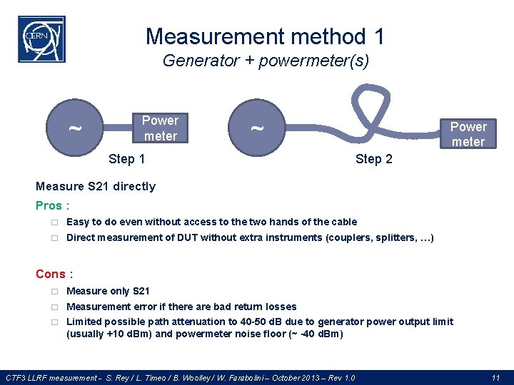
Measurement method 1 Generator + powermeter(s) ~ Power meter ~ Step 1 Power meter Step 2 Measure S 21 directly Pros : � Easy to do even without access to the two hands of the cable � Direct measurement of DUT without extra instruments (couplers, splitters, …) Cons : � Measure only S 21 � Measurement error if there are bad return losses � Limited possible path attenuation to 40 -50 d. B due to generator power output limit (usually +10 d. Bm) and powermeter noise floor (~ -40 d. Bm) CTF 3 LLRF measurement - S. Rey / L. Timeo / B. Woolley / W. Farabolini – October 2013 – Rev 1. 0 11
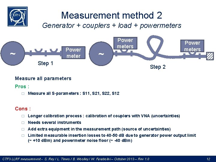
Measurement method 2 Generator + couplers + load + powermeters Power meter ~ ~ Power meters Step 1 Power meters Step 2 Measure all parameters Pros : � Measure all S-parameters : S 11, S 22, S 12 Cons : � Longer calibration process : calibration of couplers with VNA (uncertainties) � Needs several instruments � Add extra equipment in the measurement path (source of uncertainties) � Limited measurable insertion losses to 40 -50 d. B due to generator power output limit (~ +10 d. Bm) and powermeter noise floor (~ -40 d. Bm) CTF 3 LLRF measurement - S. Rey / L. Timeo / B. Woolley / W. Farabolini – October 2013 – Rev 1. 0 12
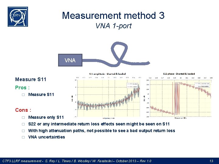
Measurement method 3 VNA 1 -port VNA Measure S 11 Pros : � Measure S 11 Cons : � Measure only S 11 � S 22 or any intermediate return loss effects seen might be seen on S 11 � With high attenuation paths, not possible to see a bad output return loss � VNA uncertainties CTF 3 LLRF measurement - S. Rey / L. Timeo / B. Woolley / W. Farabolini – October 2013 – Rev 1. 0 13
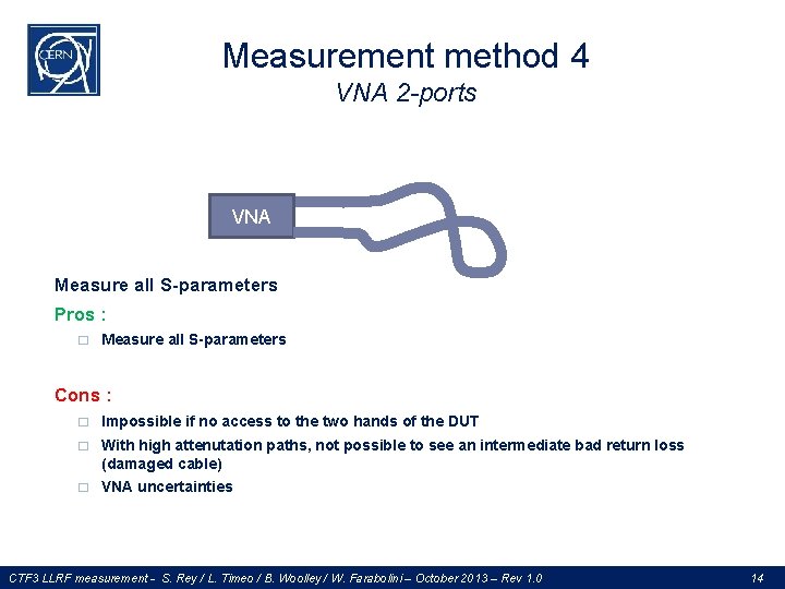
Measurement method 4 VNA 2 -ports VNA Measure all S-parameters Pros : � Measure all S-parameters Cons : � Impossible if no access to the two hands of the DUT � With high attenutation paths, not possible to see an intermediate bad return loss (damaged cable) � VNA uncertainties CTF 3 LLRF measurement - S. Rey / L. Timeo / B. Woolley / W. Farabolini – October 2013 – Rev 1. 0 14
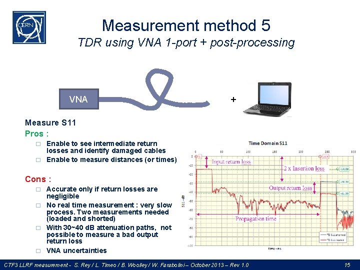
Measurement method 5 TDR using VNA 1 -port + post-processing VNA + Measure S 11 Pros : � � Enable to see intermediate return losses and identify damaged cables Enable to measure distances (or times) Cons : � � Accurate only if return losses are negligible No real time measurement : very slow process. Two measurements needed (loaded and shorted) With 30~40 d. B attenuation paths, not possible to measure a bad output return loss VNA uncertainties CTF 3 LLRF measurement - S. Rey / L. Timeo / B. Woolley / W. Farabolini – October 2013 – Rev 1. 0 15
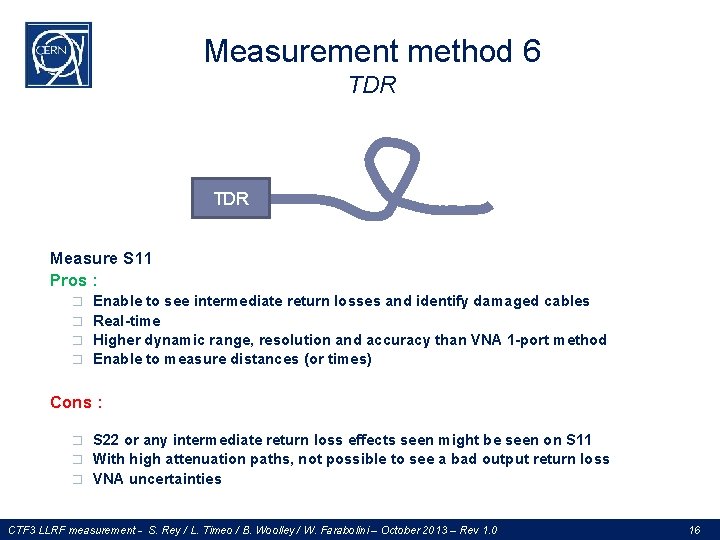
Measurement method 6 TDR Measure S 11 Pros : � � Enable to see intermediate return losses and identify damaged cables Real-time Higher dynamic range, resolution and accuracy than VNA 1 -port method Enable to measure distances (or times) Cons : � � � S 22 or any intermediate return loss effects seen might be seen on S 11 With high attenuation paths, not possible to see a bad output return loss VNA uncertainties CTF 3 LLRF measurement - S. Rey / L. Timeo / B. Woolley / W. Farabolini – October 2013 – Rev 1. 0 16
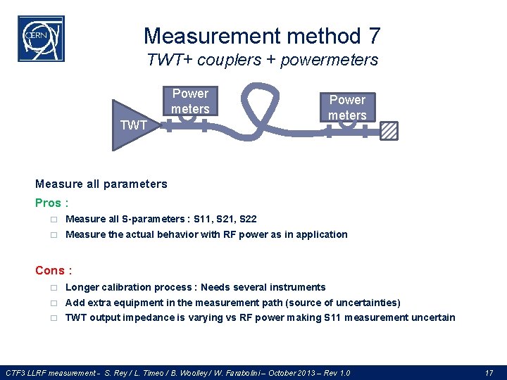
Measurement method 7 TWT+ couplers + powermeters Power meters TWT Power meters Measure all parameters Pros : � Measure all S-parameters : S 11, S 22 � Measure the actual behavior with RF power as in application Cons : � Longer calibration process : Needs several instruments � Add extra equipment in the measurement path (source of uncertainties) � TWT output impedance is varying vs RF power making S 11 measurement uncertain CTF 3 LLRF measurement - S. Rey / L. Timeo / B. Woolley / W. Farabolini – October 2013 – Rev 1. 0 17
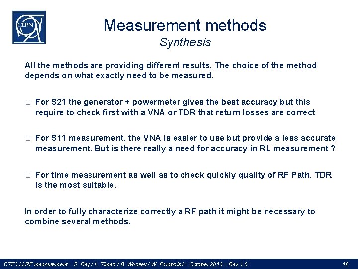
Measurement methods Synthesis All the methods are providing different results. The choice of the method depends on what exactly need to be measured. � For S 21 the generator + powermeter gives the best accuracy but this require to check first with a VNA or TDR that return losses are correct � For S 11 measurement, the VNA is easier to use but provide a less accurate measurement. But is there really a need for accuracy in RL measurement ? � For time measurement as well as to check quickly quality of RF Path, TDR is the most suitable. In order to fully characterize correctly a RF path it might be necessary to combine several methods. CTF 3 LLRF measurement - S. Rey / L. Timeo / B. Woolley / W. Farabolini – October 2013 – Rev 1. 0 18
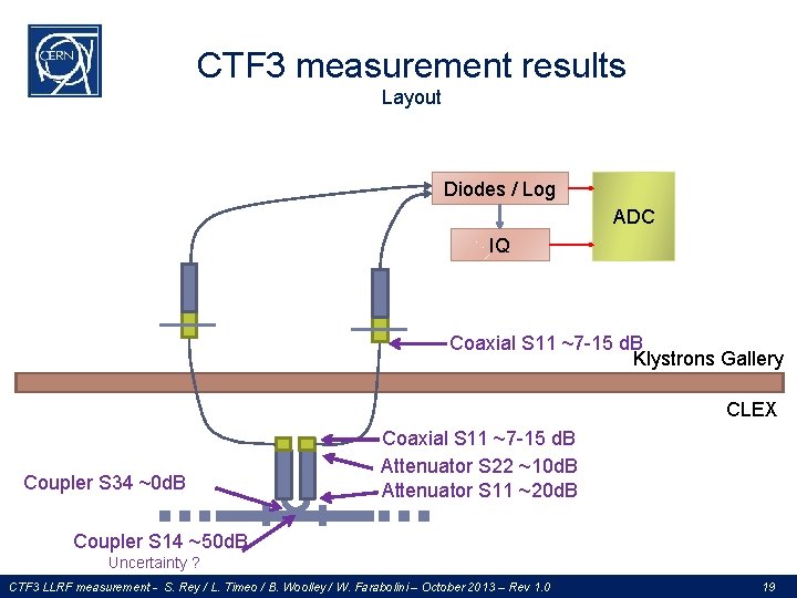
CTF 3 measurement results Layout Diodes / Log ADC IQ Coaxial S 11 ~7 -15 d. B Klystrons Gallery CLEX Coupler S 34 ~0 d. B Coaxial S 11 ~7 -15 d. B Attenuator S 22 ~10 d. B Attenuator S 11 ~20 d. B Coupler S 14 ~50 d. B Uncertainty ? CTF 3 LLRF measurement - S. Rey / L. Timeo / B. Woolley / W. Farabolini – October 2013 – Rev 1. 0 19
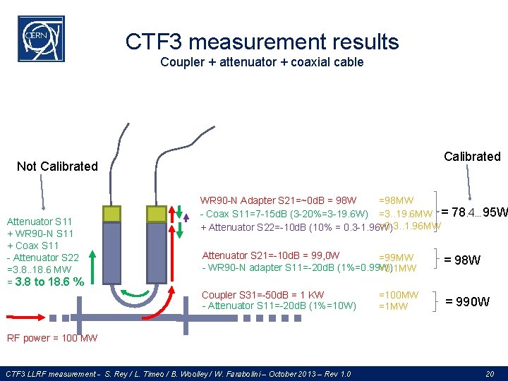
CTF 3 measurement results Coupler + attenuator + coaxial cable Calibrated Not Calibrated Attenuator S 11 + WR 90 -N S 11 + Coax S 11 - Attenuator S 22 =3. 8. . 18. 6 MW = 3. 8 to 18. 6 % WR 90 -N Adapter S 21=~0 d. B = 98 W =98 MW - Coax S 11=7 -15 d. B (3 -20%=3 -19. 6 W) =3. . 19. 6 MW = =0. 3. . 1. 96 MW + Attenuator S 22=-10 d. B (10% = 0. 3 -1. 96 W) 78. 4… 95 W Attenuator S 21=-10 d. B = 99, 0 W =99 MW - WR 90 -N adapter S 11=-20 d. B (1%=0. 99 W) =0. 1 MW = 98 W Coupler S 31=-50 d. B = 1 KW - Attenuator S 11=-20 d. B (1%=10 W) = 990 W =100 MW =1 MW RF power = 100 MW CTF 3 LLRF measurement - S. Rey / L. Timeo / B. Woolley / W. Farabolini – October 2013 – Rev 1. 0 20
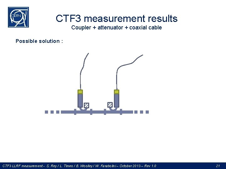
CTF 3 measurement results Coupler + attenuator + coaxial cable Possible solution : CTF 3 LLRF measurement - S. Rey / L. Timeo / B. Woolley / W. Farabolini – October 2013 – Rev 1. 0 21
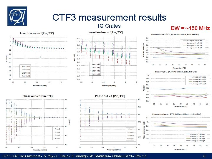
CTF 3 measurement results IQ Crates CTF 3 LLRF measurement - S. Rey / L. Timeo / B. Woolley / W. Farabolini – October 2013 – Rev 1. 0 BW = ~150 MHz ! 22
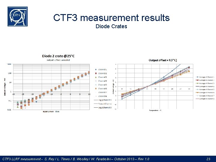
CTF 3 measurement results Diode Crates CTF 3 LLRF measurement - S. Rey / L. Timeo / B. Woolley / W. Farabolini – October 2013 – Rev 1. 0 23
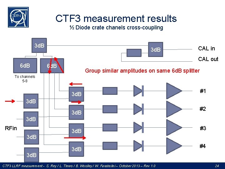
CTF 3 measurement results ½ Diode crate chanels cross-coupling 3 d. B CAL in CAL out 6 d. B Group similar amplitudes on same 6 d. B splitter To channels 5 -8 3 d. B #1 3 d. B #2 3 d. B RFin 3 d. B CTF 3 LLRF measurement - S. Rey / L. Timeo / B. Woolley / W. Farabolini – October 2013 – Rev 1. 0 #3 #4 24
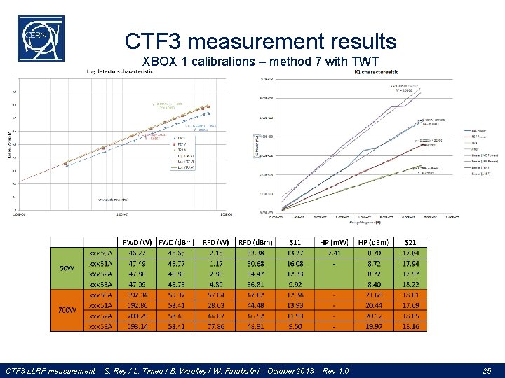
CTF 3 measurement results XBOX 1 calibrations – method 7 with TWT CTF 3 LLRF measurement - S. Rey / L. Timeo / B. Woolley / W. Farabolini – October 2013 – Rev 1. 0 25
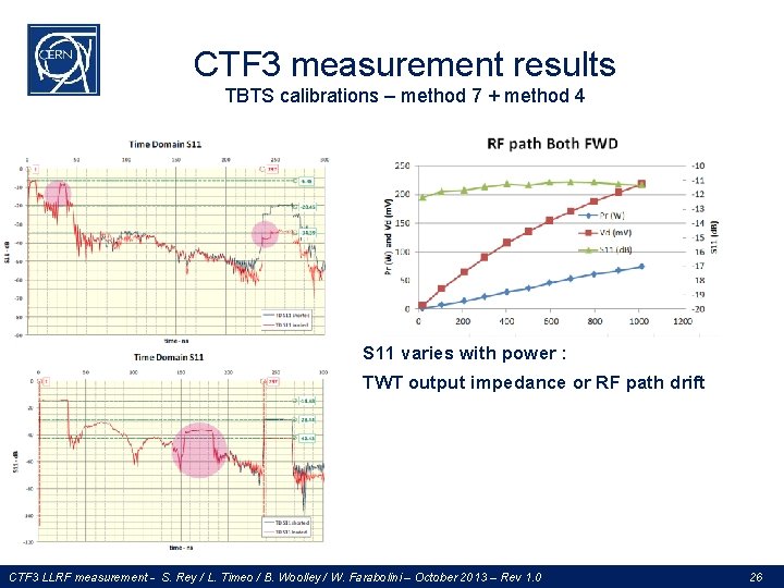
CTF 3 measurement results TBTS calibrations – method 7 + method 4 S 11 varies with power : TWT output impedance or RF path drift CTF 3 LLRF measurement - S. Rey / L. Timeo / B. Woolley / W. Farabolini – October 2013 – Rev 1. 0 26
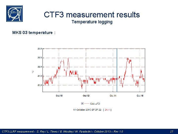
CTF 3 measurement results Temperature logging MKS 03 temperature : CTF 3 LLRF measurement - S. Rey / L. Timeo / B. Woolley / W. Farabolini – October 2013 – Rev 1. 0 27
CTF 3 measurement results Conclusions � Layout modifications for detectors dynamic optimization & general improvement � Full RF paths characterizations with several methods giving different results are needed � instruments & layout mismatches leads to uncertainties � Next ? � Methods validations in lab on reference cable � Continue equipment characterizations (automatic tests bench, climate room) : � Replace our detectors technology � Current designs : � Down-mixing detector (design for XBOX 2) � New log detectors crate � Investigate on direct acquisitions closer to the machine � Investigate on RF & clock distribution quality (phase noise, spurs) CTF 3 LLRF measurement - S. Rey / L. Timeo / B. Woolley / W. Farabolini – October 2013 – Rev 1. 0 28
- Slides: 28