CSCI365 Computer Organization Lecture 19 Note Some slides


 31")


")
- Slides: 11
CSCI-365 Computer Organization Lecture 19 Note: Some slides and/or pictures in the following are adapted from: Computer Organization and Design, Patterson & Hennessy, © 2005 Some slides and/or pictures in the following are adapted from: slides © 2008 UCB
Fetching Instructions • Fetching instructions involves – reading the instruction from the Instruction Memory – updating the PC to hold the address of the next instruction – PC is updated every cycle, so it does not need an explicit write control signal – Instruction Memory is read every cycle, so it doesn’t need an explicit read control signal Add 4 Instruction Memory PC Read Address Instruction
Decoding Instructions • Decoding instructions involves – sending the fetched instruction’s opcode and function field bits to the control unit – reading two values from the Register File • Register File addresses are contained in the instruction Control Unit Instruction Read Addr 1 Read Register Read Addr 2 Data 1 File Write Addr Read Write Data 2
Executing R Format Operations • R format operations (add, sub, slt, and, or) 31 R-type: op 25 rs 20 15 rt rd 10 5 0 shamt funct – perform the (op and funct) operation on values in rs and rt – store the result back into the Register File (into location rd) Reg. Write Instruction Read Addr 1 Register Read Addr 2 Data 1 File Write Addr Read Write Data ALU control ALU overflow zero Data 2 – The Register File is not written every cycle (e. g. sw), so we need an explicit write control signal for the Register File
Executing Load and Store Operations • Load and store operations involve – compute memory address by adding the base register (read from the Register File during decode) to the 16 -bit signed-extended offset field in the instruction – store value (read from the Register File during decode) written to the Data Memory – load value, read from the Data Memory, written to the Register File Reg. Write Instruction ALU control overflow zero Read Addr 1 Register Read Addr 2 Data 1 File Write Addr Read Write Data 16 Address ALU Data Memory Read Data Write Data 2 Sign Extend Mem. Write Mem. Read 32
Executing Branch Operations Add 4 Add Shift left 2 Branch target address ALU control PC • Branch operations involves Instruction – compare the operands read from the Register File during decode for equality (zero ALU output) – compute the branch target address by adding the updated PC to the 16 bit signed-extended offset field in the instr Read Addr 1 Register Read Addr 2 Data 1 File Write Addr Read Write Data 16 Data 2 Sign Extend 32 zero (to branch control logic) ALU
Executing Jump Operations • Jump operation involves – replace the lower 28 bits of the PC with the lower 26 bits of the fetched instruction shifted left by 2 bits Add 4 4 Instruction Memory PC Read Address Instruction Shift left 2 26 Jump address 28
Creating a Single Datapath from the Parts • Assemble the datapath segments and add control lines and multiplexors as needed • Single cycle design – fetch, decode and execute each instructions in one clock cycle – no datapath resource can be used more than once per instruction, so some must be duplicated (e. g. , separate Instruction Memory and Data Memory, several adders) – multiplexors needed at the input of shared elements with control lines to do the selection – write signals to control writing to the Register File and Data Memory • Cycle time is determined by length of the longest path
Single Cycle Datapath with Control Unit 0 Add ALUOp Reg. Dst PC Read Address Instr[31 -0] Mem. Read Memto. Reg Mem. Write ALUSrc Reg. Write ovf Instr[25 -21] Read Addr 1 Register Read Instr[20 -16] Read Addr 2 Data 1 File 0 Write Addr Read 1 Instr[15 -11] Instr[15 -0] 1 PCSrc Branch Instr[31 -26] Control Unit Instruction Memory Add Shift left 2 4 Write Data zero 0 ALU Data 2 1 Sign 16 Extend 32 Instr[5 -0] ALU control Address Data Memory Read Data 1 Write Data 0
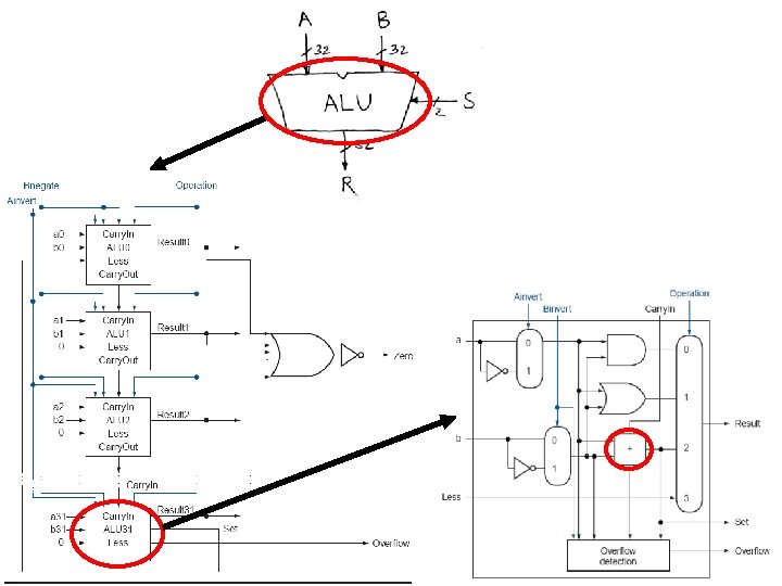
The ALU Control (DONE IN CLASS)