
CSCE 436 Advanced Embedded Systems Lecture 10 Finite
CSCE 436 – Advanced Embedded Systems Lecture 10 – Finite State Machines Prof Jeffrey Falkinburg Avery Hall 368 472 -5120
Lesson Outline n Time Logs! n Lab 1 Write-up Due COB! 1. D Flip Flop 2. Finite State Machine 3. FSM Timing 4. The DAISY System CSCE 436 – Advanced Embedded Systems 2
D Flip Flop CSCE 436 – Advanced Embedded Systems 3
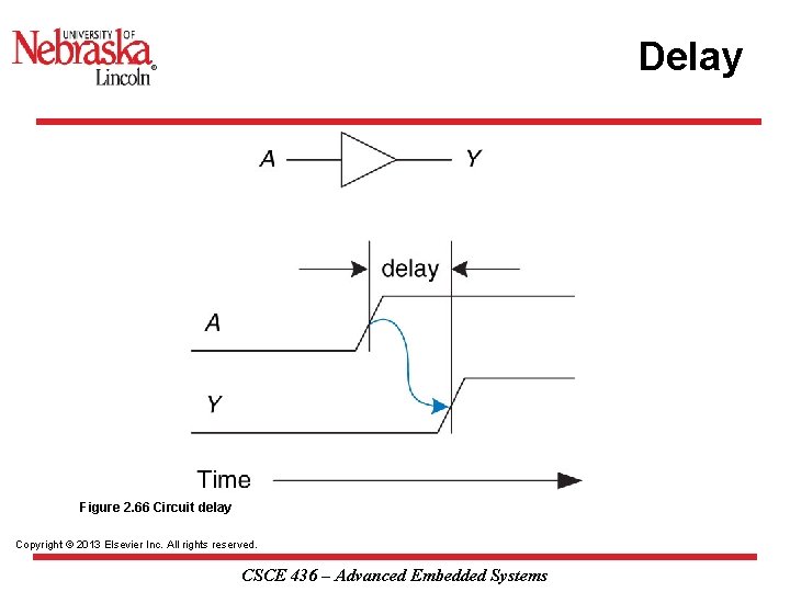
Delay Figure 2. 66 Circuit delay Copyright © 2013 Elsevier Inc. All rights reserved. CSCE 436 – Advanced Embedded Systems
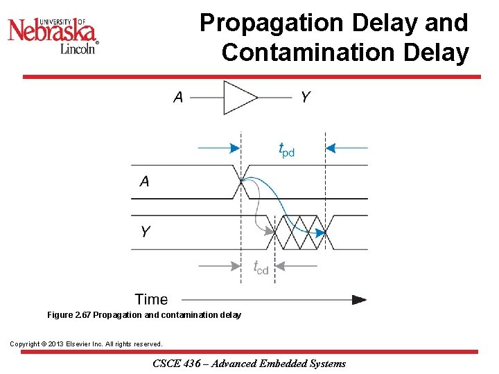
Propagation Delay and Contamination Delay Figure 2. 67 Propagation and contamination delay Copyright © 2013 Elsevier Inc. All rights reserved. CSCE 436 – Advanced Embedded Systems
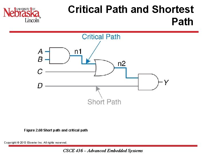
Critical Path and Shortest Path Figure 2. 68 Short path and critical path Copyright © 2013 Elsevier Inc. All rights reserved. CSCE 436 – Advanced Embedded Systems
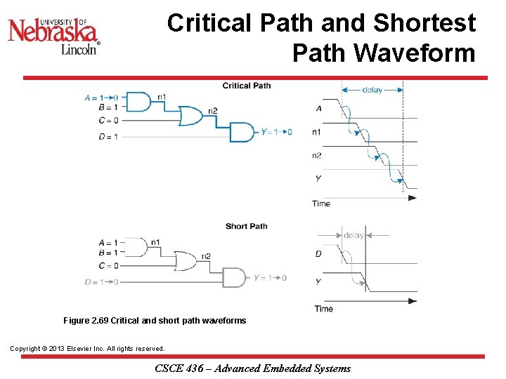
Critical Path and Shortest Path Waveform Figure 2. 69 Critical and short path waveforms Copyright © 2013 Elsevier Inc. All rights reserved. CSCE 436 – Advanced Embedded Systems
D Flip Flop Setup time(tsu) - is the amount of time before the rising edge of the clock in which the data inputs must be stable. n Hold time(th) is the amount of time after the rising edge of the clock during which the data input must be stable. n Propagation Delay(tp), is the amount of time after the rising edge of the clock required for the new Q value to become valid. n n 12 June 2021 It is also known as t. CQ, for "time clock to Q", or t. FF. These time values are illustrated in the picture below. CSCE 436 – Advanced Embedded Systems 8
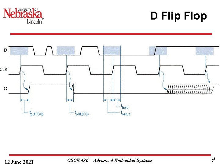
D Flip Flop 12 June 2021 CSCE 436 – Advanced Embedded Systems 9
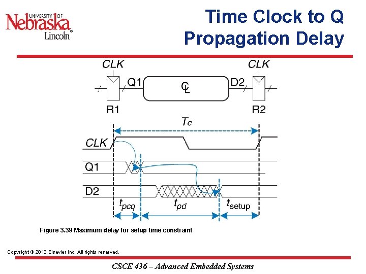
Time Clock to Q Propagation Delay Figure 3. 39 Maximum delay for setup time constraint Copyright © 2013 Elsevier Inc. All rights reserved. CSCE 436 – Advanced Embedded Systems
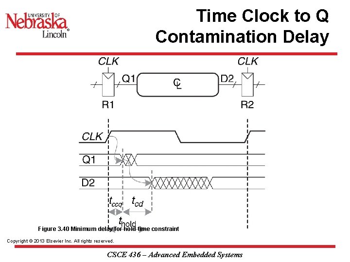
Time Clock to Q Contamination Delay Figure 3. 40 Minimum delay for hold time constraint Copyright © 2013 Elsevier Inc. All rights reserved. CSCE 436 – Advanced Embedded Systems
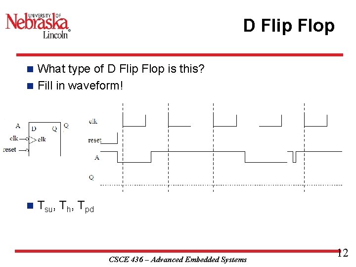
D Flip Flop What type of D Flip Flop is this? n Fill in waveform! n n Tsu, Th, Tpd CSCE 436 – Advanced Embedded Systems 12
Finite State Machine CSCE 436 – Advanced Embedded Systems 13
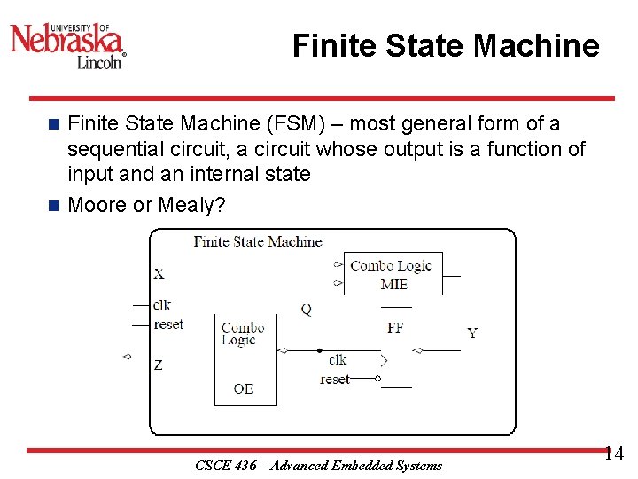
Finite State Machine (FSM) – most general form of a sequential circuit, a circuit whose output is a function of input and an internal state n Moore or Mealy? n CSCE 436 – Advanced Embedded Systems 14
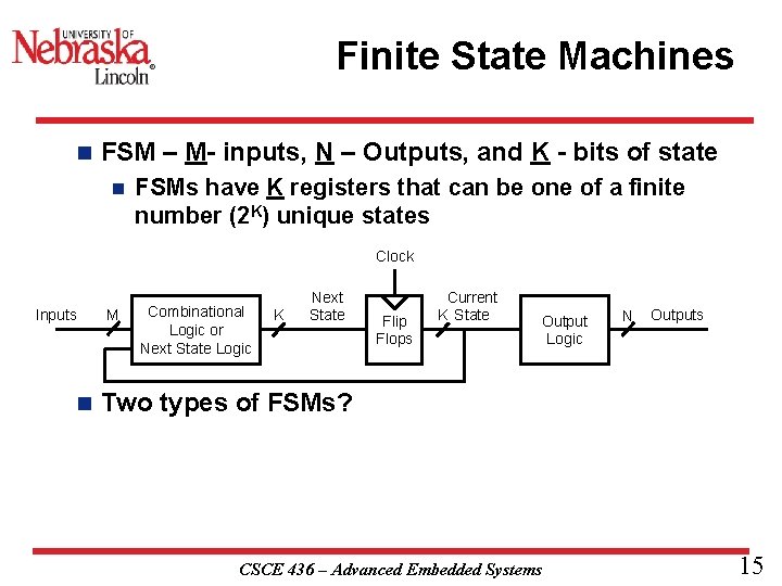
Finite State Machines n FSM – M- inputs, N – Outputs, and K - bits of state n FSMs have K registers that can be one of a finite number (2 K) unique states Clock Inputs n M Combinational Logic or Next State Logic K Next State Flip Flops Current K State Output Logic N Outputs Two types of FSMs? CSCE 436 – Advanced Embedded Systems 15
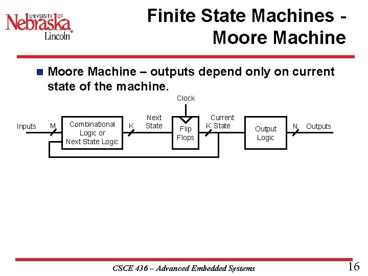
Finite State Machines Moore Machine n Moore Machine – outputs depend only on current state of the machine. Clock Inputs M Combinational Logic or Next State Logic K Next State Flip Flops Current K State Output Logic CSCE 436 – Advanced Embedded Systems N Outputs 16
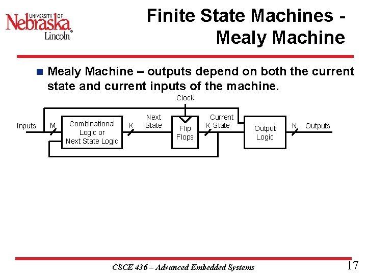
Finite State Machines Mealy Machine n Mealy Machine – outputs depend on both the current state and current inputs of the machine. Clock Inputs M Combinational Logic or Next State Logic K Next State Flip Flops Current K State Output Logic CSCE 436 – Advanced Embedded Systems N Outputs 17
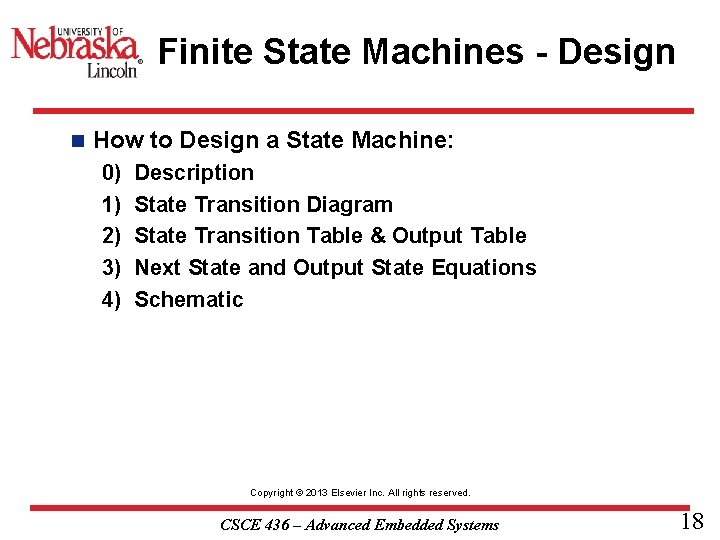
Finite State Machines - Design n How to Design a State Machine: 0) 1) 2) 3) 4) Description State Transition Diagram State Transition Table & Output Table Next State and Output State Equations Schematic Copyright © 2013 Elsevier Inc. All rights reserved. CSCE 436 – Advanced Embedded Systems 18
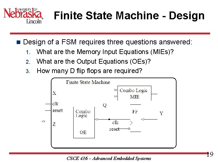
Finite State Machine - Design n Design of a FSM requires three questions answered: What are the Memory Input Equations (MIEs)? 2. What are the Output Equations (OEs)? 3. How many D flip flops are required? 1. CSCE 436 – Advanced Embedded Systems 19
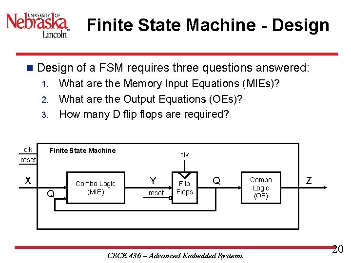
Finite State Machine - Design n Design of a FSM requires three questions answered: What are the Memory Input Equations (MIEs)? 2. What are the Output Equations (OEs)? 3. How many D flip flops are required? 1. clk reset Finite State Machine X Q Combo Logic (MIE) clk Y reset Flip Flops Q CSCE 436 – Advanced Embedded Systems Combo Logic (OE) Z 20
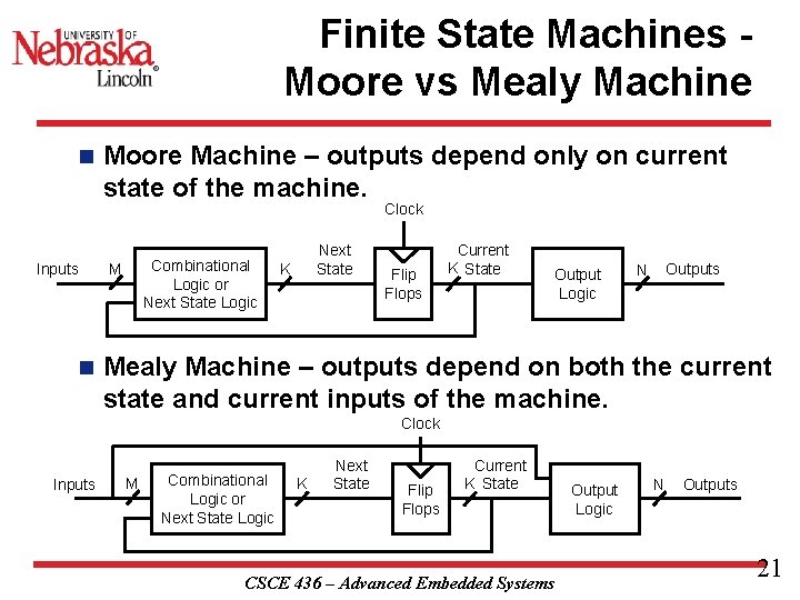
Finite State Machines Moore vs Mealy Machine n Moore Machine – outputs depend only on current state of the machine. Clock Inputs n Combinational Logic or Next State Logic M Next State K Flip Flops Current K State Output Logic Outputs N Mealy Machine – outputs depend on both the current state and current inputs of the machine. Clock Inputs M Combinational Logic or Next State Logic K Next State Flip Flops Current K State CSCE 436 – Advanced Embedded Systems Output Logic N Outputs 21
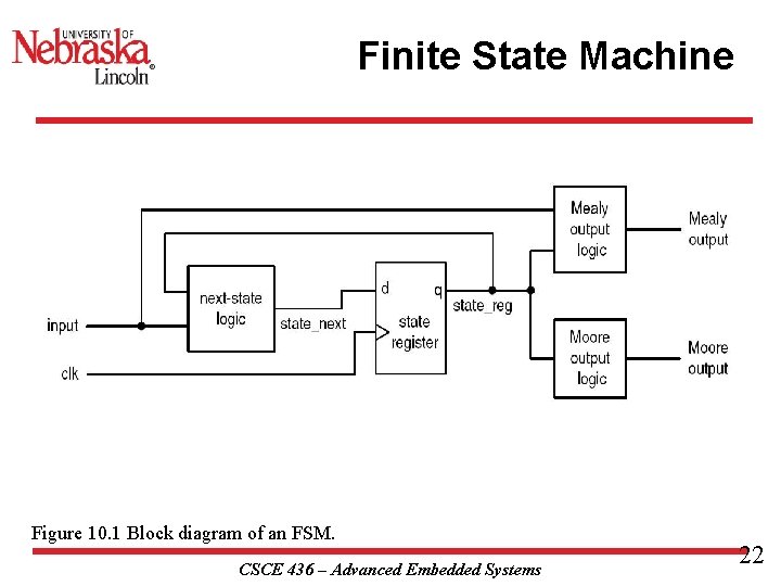
Finite State Machine Figure 10. 1 Block diagram of an FSM. CSCE 436 – Advanced Embedded Systems 22
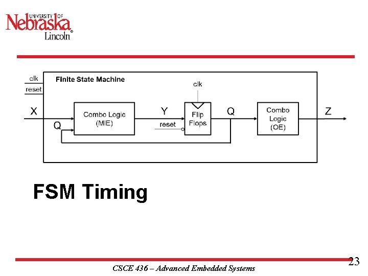
FSM Timing CSCE 436 – Advanced Embedded Systems 23
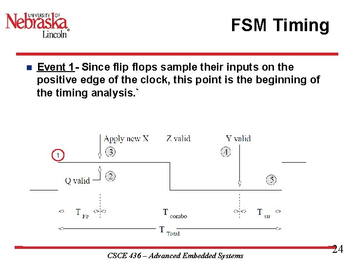
FSM Timing n Event 1 - Since flip flops sample their inputs on the positive edge of the clock, this point is the beginning of the timing analysis. ` 1 CSCE 436 – Advanced Embedded Systems 24
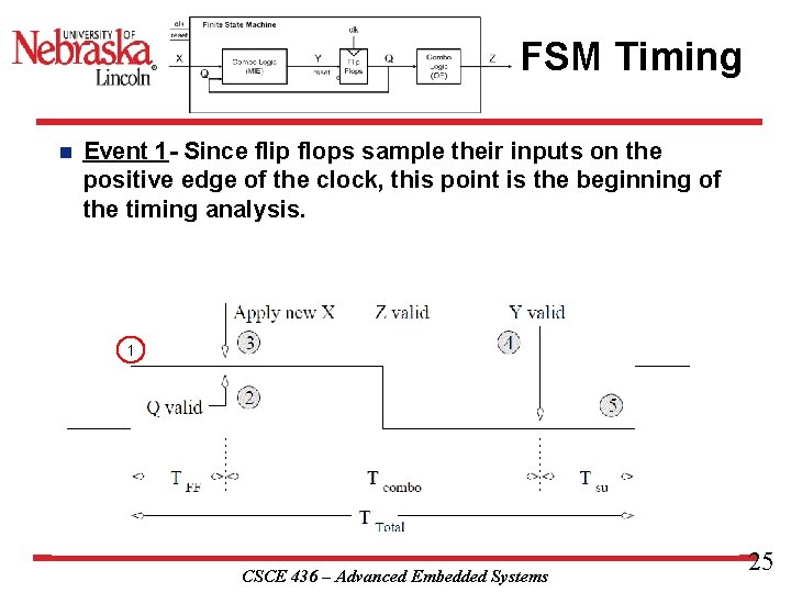
FSM Timing n Event 1 - Since flip flops sample their inputs on the positive edge of the clock, this point is the beginning of the timing analysis. 1 CSCE 436 – Advanced Embedded Systems 25
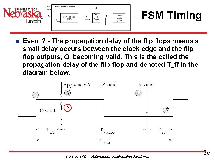
FSM Timing n Event 2 - The propagation delay of the flip flops means a small delay occurs between the clock edge and the flip flop outputs, Q, becoming valid. This is the called the propagation delay of the flip flop and denoted T_ff in the diagram below. 2 CSCE 436 – Advanced Embedded Systems 26
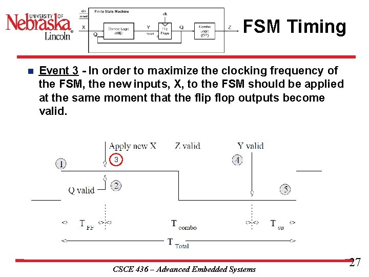
FSM Timing n Event 3 - In order to maximize the clocking frequency of the FSM, the new inputs, X, to the FSM should be applied at the same moment that the flip flop outputs become valid. 3 CSCE 436 – Advanced Embedded Systems 27
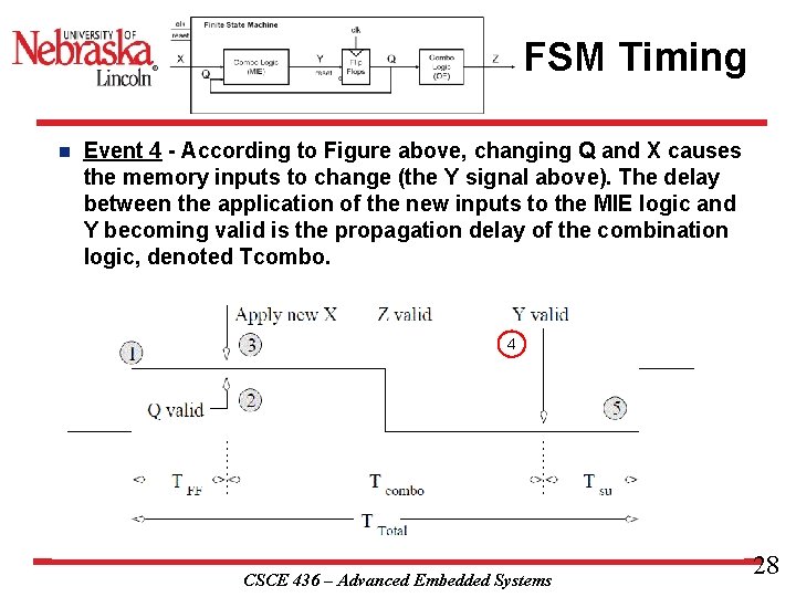
FSM Timing n Event 4 - According to Figure above, changing Q and X causes the memory inputs to change (the Y signal above). The delay between the application of the new inputs to the MIE logic and Y becoming valid is the propagation delay of the combination logic, denoted Tcombo. 4 CSCE 436 – Advanced Embedded Systems 28
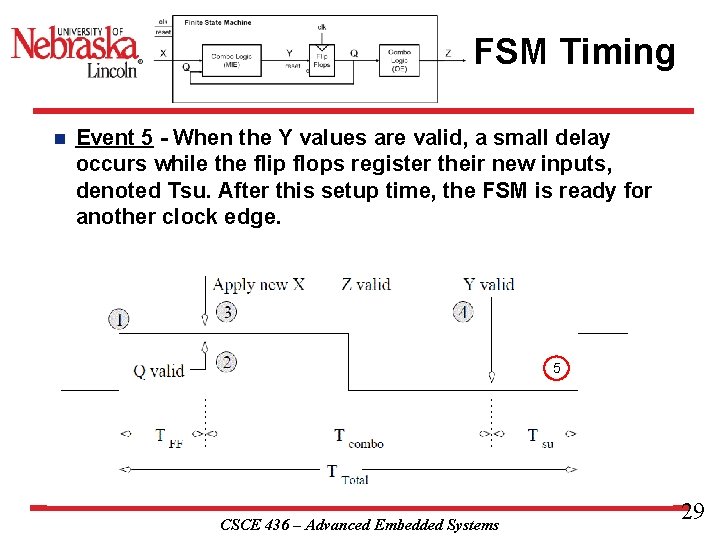
FSM Timing n Event 5 - When the Y values are valid, a small delay occurs while the flip flops register their new inputs, denoted Tsu. After this setup time, the FSM is ready for another clock edge. 5 CSCE 436 – Advanced Embedded Systems 29
Lets bring in the cows. The DAISY System CSCE 436 – Advanced Embedded Systems 30
The DAISY System Dairy Automated Information System, or DAISY for short n Word Statement Cows have a RFID tag attached to their collars. When the cow passes through the cattle chute on their way into the barn, a RFID reader reads the unique ID stored on the RFID tag and logs the cow into the barn. n The RFID system outputs a single bit: a 1 means the system has read an RFID tag and has successfully checked a cow back into the barn; a 0 means the RFID system is either still processing a tag or is not currently reading a tag. n The RFID system outputs a single bit: n Logic 1 – Cow Checked In n Logic 0 – Cow Not Processed n CSCE 436 – Advanced Embedded Systems 31
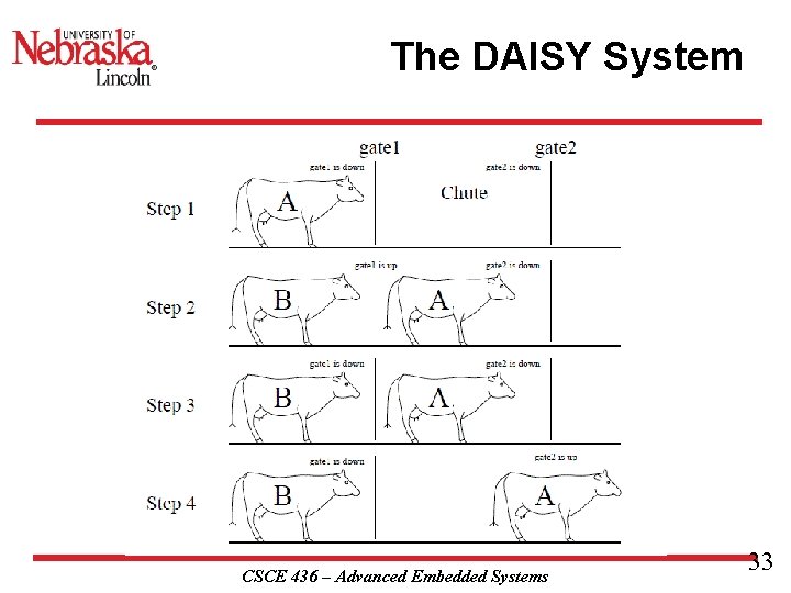
The DAISY System n In order to ensure each cow is scanned, the flow of cows into the barn is controlled by two gates at either end of the chute. Each gate is controlled by a single bit. To lift a gate, this input must be held at logic 1; to lower a gate, the input must be held at a logic 0. The sequence of raising and lowering the gates in order to control the flow of cows. n Flow of cows is controlled by two gates Logic 1 – To lift a gate n Logic 0 – To lower a gate n CSCE 436 – Advanced Embedded Systems 32
The DAISY System CSCE 436 – Advanced Embedded Systems 33
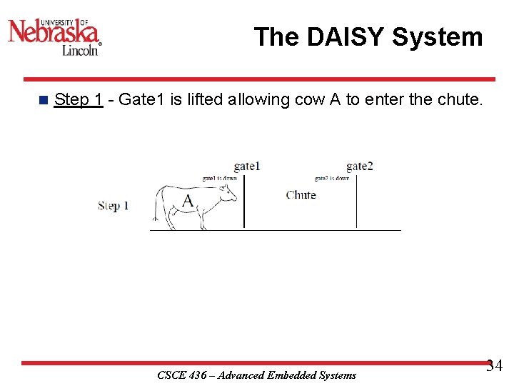
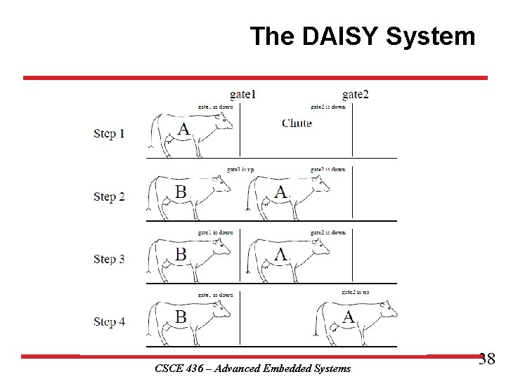
The DAISY System n Step 1 - Gate 1 is lifted allowing cow A to enter the chute. CSCE 436 – Advanced Embedded Systems 34
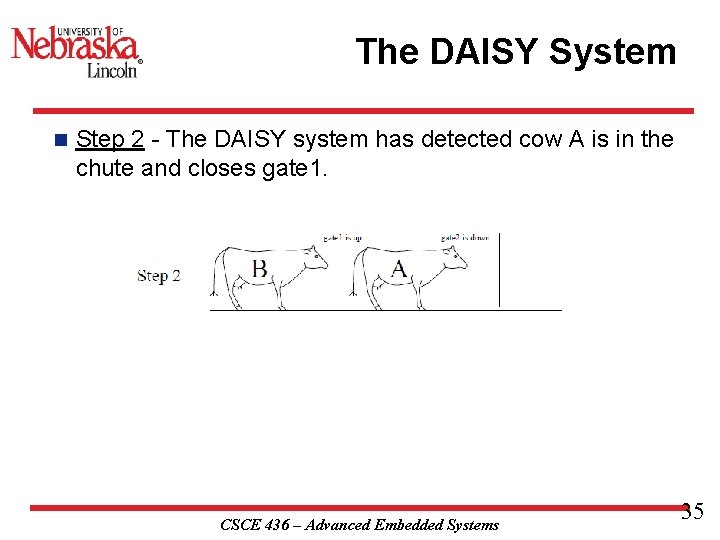
The DAISY System n Step 2 - The DAISY system has detected cow A is in the chute and closes gate 1. CSCE 436 – Advanced Embedded Systems 35
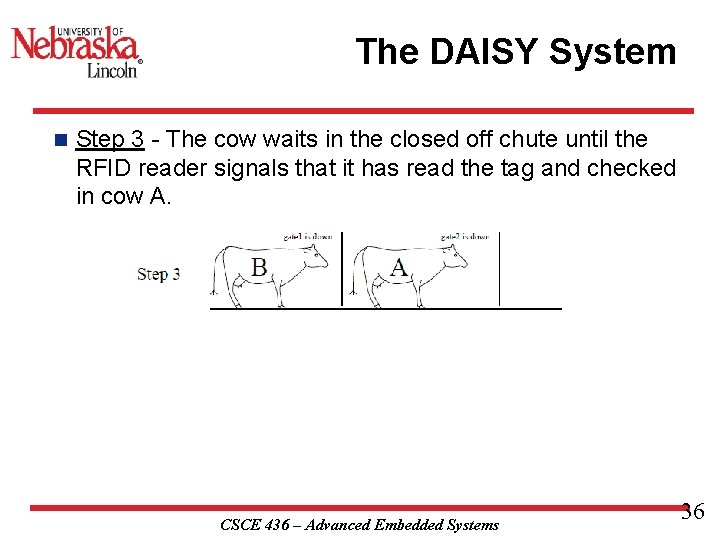
The DAISY System n Step 3 - The cow waits in the closed off chute until the RFID reader signals that it has read the tag and checked in cow A. CSCE 436 – Advanced Embedded Systems 36
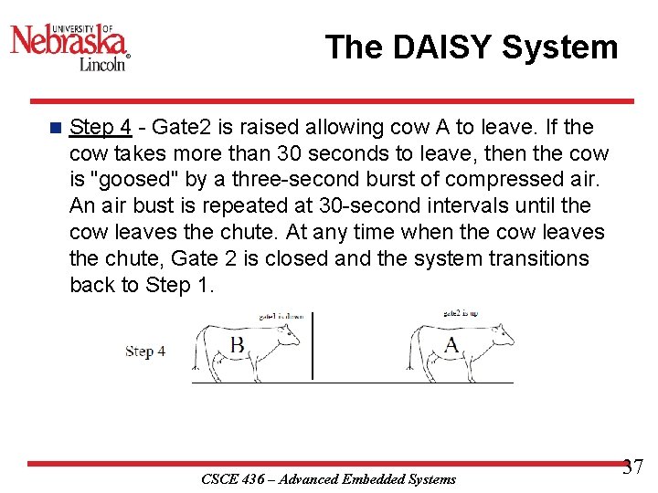
The DAISY System n Step 4 - Gate 2 is raised allowing cow A to leave. If the cow takes more than 30 seconds to leave, then the cow is "goosed" by a three-second burst of compressed air. An air bust is repeated at 30 -second intervals until the cow leaves the chute. At any time when the cow leaves the chute, Gate 2 is closed and the system transitions back to Step 1. CSCE 436 – Advanced Embedded Systems 37
The DAISY System CSCE 436 – Advanced Embedded Systems 38
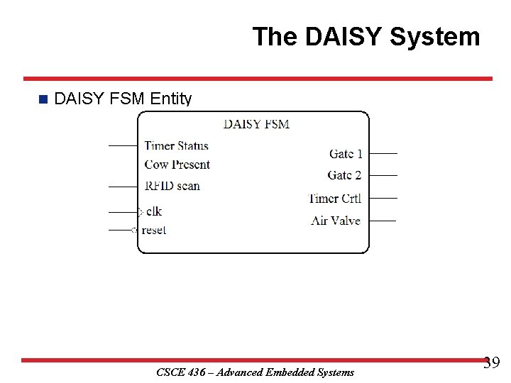
The DAISY System n DAISY FSM Entity CSCE 436 – Advanced Embedded Systems 39
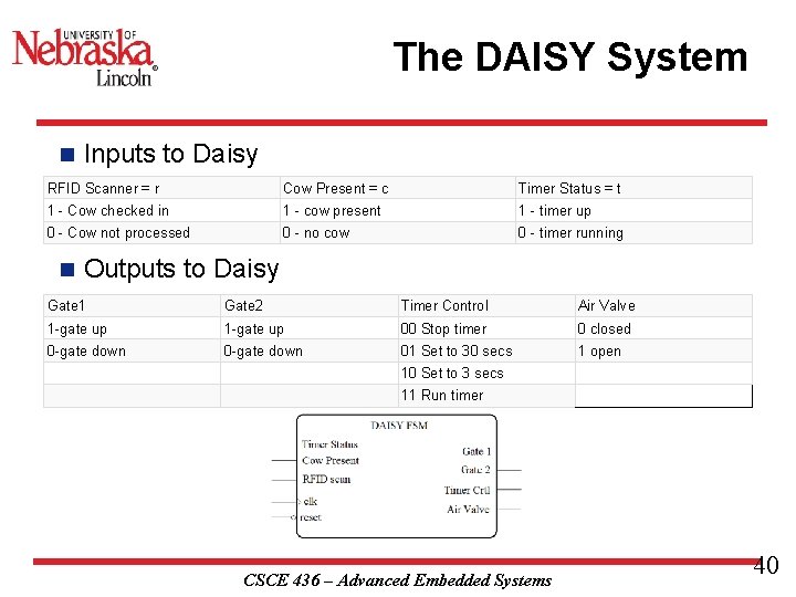
The DAISY System n Inputs to Daisy RFID Scanner = r Cow Present = c Timer Status = t 1 - Cow checked in 1 - cow present 1 - timer up 0 - Cow not processed 0 - no cow 0 - timer running n Outputs to Daisy Gate 1 Gate 2 Timer Control Air Valve 1 -gate up 00 Stop timer 0 closed 0 -gate down 01 Set to 30 secs 1 open 10 Set to 3 secs 11 Run timer CSCE 436 – Advanced Embedded Systems 40
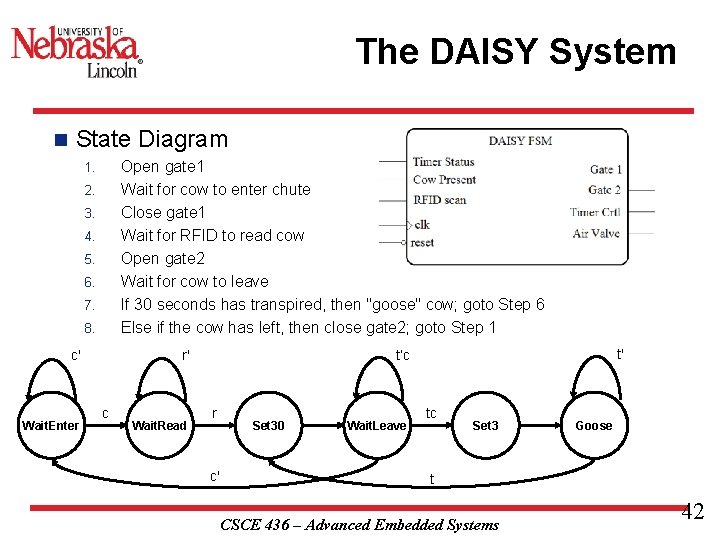
The DAISY System n State Diagram Open gate 1 Wait for cow to enter chute Close gate 1 Wait for RFID to read cow Open gate 2 Wait for cow to leave If 30 seconds has transpired, then "goose" cow; goto Step 6 Else if the cow has left, then close gate 2; goto Step 1 1. 2. 3. 4. 5. 6. 7. 8. c' Wait. Enter c Wait. Read t' t’c r' r c' Set 30 Wait. Leave tc Set 3 Goose t CSCE 436 – Advanced Embedded Systems 42
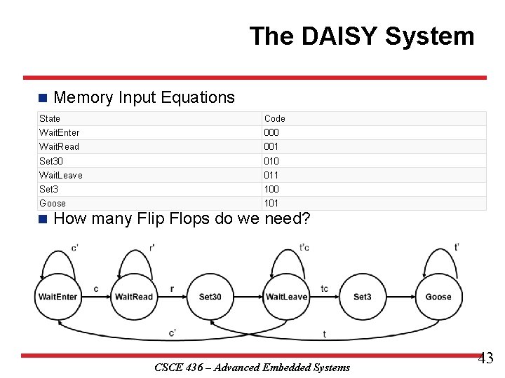
The DAISY System n Memory Input Equations State Code Wait. Enter 000 Wait. Read 001 Set 30 010 Wait. Leave 011 Set 3 100 Goose 101 n How many Flip Flops do we need? CSCE 436 – Advanced Embedded Systems 43
The DAISY System n Solve for three (one for each flip flop) 6 -input Boolean Expressions n Using espresso CSCE 436 – Advanced Embedded Systems 44
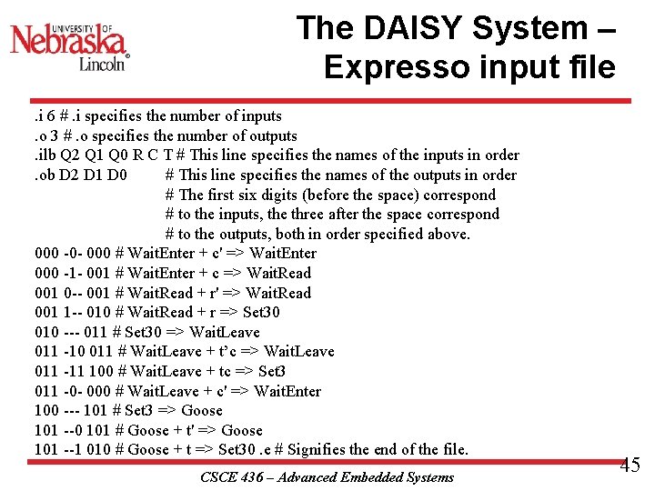
The DAISY System – Expresso input file. i 6 #. i specifies the number of inputs. o 3 #. o specifies the number of outputs. ilb Q 2 Q 1 Q 0 R C T # This line specifies the names of the inputs in order. ob D 2 D 1 D 0 # This line specifies the names of the outputs in order # The first six digits (before the space) correspond # to the inputs, the three after the space correspond # to the outputs, both in order specified above. 000 -0 - 000 # Wait. Enter + c' => Wait. Enter 000 -1 - 001 # Wait. Enter + c => Wait. Read 001 0 -- 001 # Wait. Read + r' => Wait. Read 001 1 -- 010 # Wait. Read + r => Set 30 010 --- 011 # Set 30 => Wait. Leave 011 -10 011 # Wait. Leave + t’c => Wait. Leave 011 -11 100 # Wait. Leave + tc => Set 3 011 -0 - 000 # Wait. Leave + c' => Wait. Enter 100 --- 101 # Set 3 => Goose 101 --0 101 # Goose + t' => Goose 101 --1 010 # Goose + t => Set 30. e # Signifies the end of the file. CSCE 436 – Advanced Embedded Systems 45
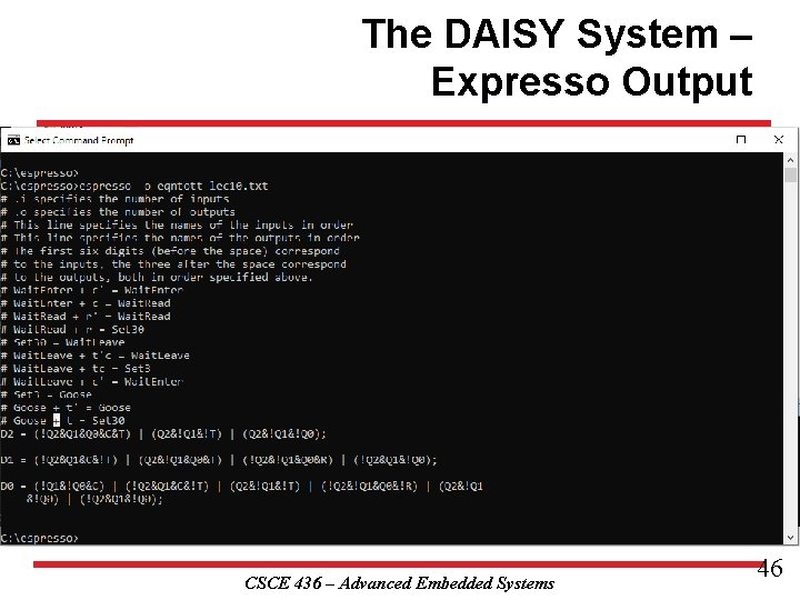
The DAISY System – Expresso Output CSCE 436 – Advanced Embedded Systems 46
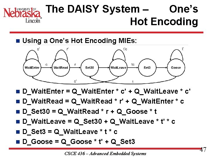
The DAISY System – One’s Hot Encoding n n n n Using a One’s Hot Encoding MIEs: State Code Wait. Enter 000001 Wait. Read 000010 Set 30 000100 Wait. Leave 001000 Set 3 010000 Goose 100000 D_Wait. Enter = Q_Wait. Enter * c' + Q_Wait. Leave * c' D_Wait. Read = Q_Wait. Read * r' + Q_Wait. Enter * c D_Set 30 = Q_Wait. Read * r + Q_Goose * t D_Wait. Leave = Q_Set 30 + Q_Wait. Leave * t' * c D_Set 3 = Q_Wait. Leave * t * c D_Goose = Q_Goose * t' + Q_Set 3 CSCE 436 – Advanced Embedded Systems 47
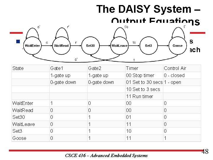
The DAISY System – Output Equations n The first step in generating the output equations is to build a control word table - a table listing, for each state, its output. State Gate 1 1 -gate up 0 -gate down Gate 2 1 -gate up 0 -gate down Wait. Enter Wait. Read Set 30 Wait. Leave Set 3 Goose 1 0 0 0 0 1 1 Timer Control Air 00 Stop timer 0 - closed 01 Set to 30 secs 1 - open 10 Set to 3 secs 11 Run timer 00 0 01 0 10 0 11 1 CSCE 436 – Advanced Embedded Systems 48
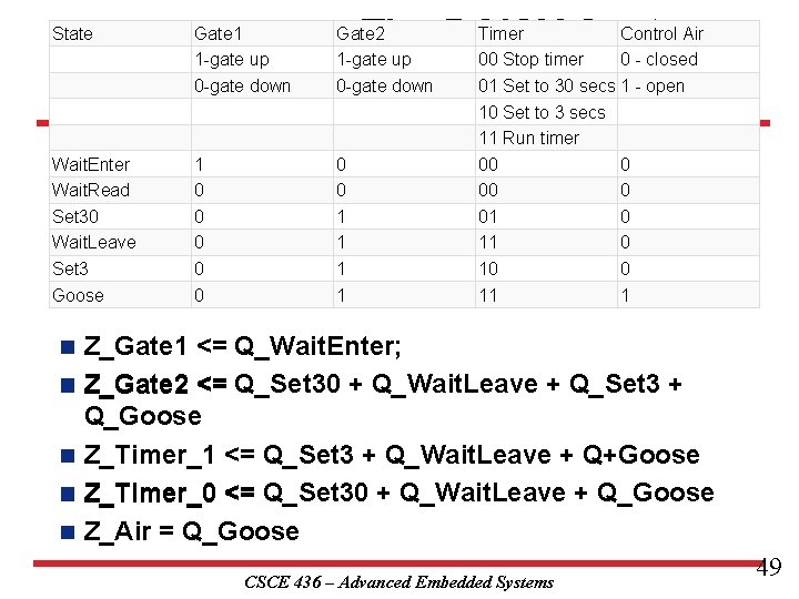
State Wait. Enter Wait. Read Set 30 Wait. Leave Set 3 Goose n n n Gate 1 1 -gate up 0 -gate down 1 0 0 0 Timer Control Air – The DAISY System 00 Stop timer 0 - closed 01 Set to 30 secs 1 - open Output Equations Gate 2 1 -gate up 0 -gate down 0 0 1 1 10 Set to 3 secs 11 Run timer 00 00 01 11 10 11 0 0 0 1 Z_Gate 1 <= Q_Wait. Enter; Z_Gate 2 <= Q_Set 30 + Q_Wait. Leave + Q_Set 3 + Q_Goose Z_Timer_1 <= Q_Set 3 + Q_Wait. Leave + Q+Goose Z_Timer_0 <= Q_Set 30 + Q_Wait. Leave + Q_Goose Z_Air = Q_Goose CSCE 436 – Advanced Embedded Systems 49
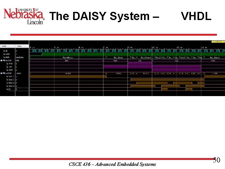
The DAISY System – CSCE 436 – Advanced Embedded Systems VHDL 50
- Slides: 49