CS 559 Computer Graphics Lecture 20 Project 2


 (x, y, z)")


![Option: Varieties of mappings [Paul Bourke]](https://slidetodoc.com/presentation_image/3c7ec9a2949432d59f97f1c71fd4bfa5/image-16.jpg "Option: Varieties of mappings [Paul Bourke]")
![Option: unfold the surface [Piponi 2000]](https://slidetodoc.com/presentation_image/3c7ec9a2949432d59f97f1c71fd4bfa5/image-17.jpg "Option: unfold the surface [Piponi 2000]")
![Option: make an atlas charts atlas surface [Sander 2001]](https://slidetodoc.com/presentation_image/3c7ec9a2949432d59f97f1c71fd4bfa5/image-18.jpg "Option: make an atlas charts atlas surface [Sander 2001]")


 = (x/W, y/H) •")
 = (θ/(2π), z) –")
 texture to basic map shape • Then, map")


 What’s the memory overhead? Using Trilinaer => quadrilinear")


 { gl. Clear(GL_COLOR_BUFFER_BIT | GL_DEPTH_BUFFER_BIT);")
![Initializing Texture Mapping static GLubyte image[64][4]; static GLuint texname; void init(void) { gl. Clear.](https://slidetodoc.com/presentation_image/3c7ec9a2949432d59f97f1c71fd4bfa5/image-59.jpg "Initializing Texture Mapping static GLubyte image[64][4]; static GLuint texname; void init(void) { gl. Clear.")


 { gl. Clear(GL_COLOR_BUFFER_BIT | GL_DEPTH_BUFFER_BIT);")


 { gl. Clear. Color (0. 0,")


 The following code fragment is inserted into Draw( ) or")
 Here is where the extra “Texture” transformation on the vertices")


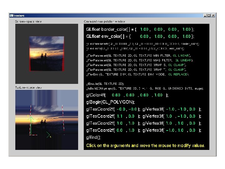
![What if (u, v) falls outside of [0, 1]? Repeat, mirror, clamp, border](https://slidetodoc.com/presentation_image/3c7ec9a2949432d59f97f1c71fd4bfa5/image-82.jpg "What if (u, v) falls outside of [0, 1]? Repeat, mirror, clamp, border")


- Slides: 156
CS 559: Computer Graphics Lecture 20: Project 2 Review and Texture mapping Li Zhang Spring 2010 Many slides from Ravi Ramamoorthi, Columbia Univ, Greg Humphreys, UVA and Rosalee Wolfe, De. Paul tutorial teaching texture mapping visually
Sample Code by Chi Man Liu
Other basic features • How to change speed? – Add a slider with a callback to change time. Per. Frame • How to orient a car? • How to draw trees? – A triangle + a rectangle – A cone + a cylinder • Using glu. Quadrics
Piecewise Cubics P 4 P 3 P 1 P 2
Piecewise Cubics Task 1: draw the whole curve Draw. Cubic(P 4, P 1, P 2, P 3); Draw. Cubic(P 1, P 2, P 3, P 4); Draw. Cubic(P 2, P 3, P 4, P 1); Draw. Cubic(P 3, P 4, P 1, P 2); Draw. Cubic(Q 1, Q 2, Q 3, Q 4) For (t=0; t < 0. 1; t+=0. 01) { A=compute. Point(Q 1, Q 2, Q 3, Q 4, t); B=compute. Point(Q 1, Q 2, Q 3, Q 4, t+0. 01); draw. Line(A, B); } Fine with Hermite, Catmull-Ron, Cardinal How about Bezier? Task 2: find where the train is at time t: If (0<=t<1) return compute. Point(P 4, P 1, P 2, P 3, t) If (1<=t<2) return compute. Point(P 1, P 2, P 3, P 4, t-1); If (2<=t<3) return compute. Point(P 2, P 3, P 4, P 1, t-2); If (3<=t<4) return compute. Point(P 3, P 4, P 1, P 2, t-3);
Arc-Length Parameterization • Arbitrary curves? P 4 P 3 P 1 P 2
Arc-length parameterization 0 1 t L 0 s Arc-length parameterization y x Freeform
Correct Orientation in 3 D • Define and interpolate up vector
Implement simple physics • Energy conservation
Multiple Cars • Each has its own parameter t, assuming arclength parameterization
Hack Shadow (XL, YL, ZL) (x, y, z)
Train smoke? • Balls moving upward and dissipating
Texture Mapping • Important topic: nearly all objects textured – Wood grain, faces, bricks and so on – Adds visual detail to scenes Polygonal model With surface texture
Adding Visual Detail • Basic idea: use images instead of more polygons to represent fine scale color variation
Parameterization + geometry = image texture map • Q: How do we decide where on the geometry each color from the image should go?
Option: Varieties of mappings [Paul Bourke]
Option: unfold the surface [Piponi 2000]
Option: make an atlas charts atlas surface [Sander 2001]
Outline • Types of mappings • Interpolating texture coordinates • Broader use of textures
How to map object to texture? • To each vertex (x, y, z in object coordinates), must associate 2 D texture coordinates (s, t) • So texture fits “nicely” over object
Implementing texture mapping • A texture lives in it own abstract image coordinates paramaterized by (u, v) in the range ([0. . 1], [0. . 1]): • It can be wrapped around many different surfaces: • Note: if the surface moves/deforms, the texture goes with it.
How to map object to texture? • To each vertex (x, y, z in object coordinates), must associate 2 D texture coordinates (s, t) • So texture fits “nicely” over object
Planar mapping • Like projections, drop z coord (u, v) = (x/W, y/H) • Problems: what happens near silhouettes?
Cylindrical Mapping • Cylinder: r, θ, z with (u, v) = (θ/(2π), z) – Note seams when wrapping around (θ = 0 or 2π)
Basic procedure • First, map (square) texture to basic map shape • Then, map basic map shape to object – Or vice versa: Object to map shape, map shape to square • Usually, this is straightforward – Maps from square to cylinder, plane, … – Maps from object to these are simply coordinate transform
Spherical Mapping • Convert to spherical coordinates: use latitude/long. – Singularities at north and south poles
Cube Mapping
Cube Mapping
Piecewise Mapping From Steve Marschner
Slides from Leonard Mcmillan
Outline • Types of projections • Interpolating texture coordinates • Broader use of textures
1 st idea: Gouraud interp. of texcoords Using barycentric Coordinates
1 st idea: Gouraud interp. of texcoords Scan line
Artifacts • Mc. Millan’s demo of this is at http: //graphics. lcs. mit. edu/classes/6. 837/F 98/Lecture 21/Slide 05. html • Another example http: //graphics. lcs. mit. edu/classes/6. 837/F 98/Lecture 21/Slide 06. html • What artifacts do you see? • Why? • Hint: problem is in interpolating parameters
Interpolating Parameters • The problem turns out to be fundamental to interpolating parameters in screen-space – Uniform steps in screen space uniform steps in world space Texture image
Linear Interpolation in Screen Space Compare linear interpolation in screen space Without loss of generality, let’s assume that the viewport is located 1 unit away from the center of projection. That is Slides from Jingyi Yu
Linear Interpolation in 3 -Space to interpolation in 3 -space: Slides from Jingyi Yu
How to make them Mesh Still need to scan convert in screen space. . . so we need a mapping from t values to s values. We know that the all points on the 3 -space edge project onto our screen-space line. Thus we can set up the following equality: and solve for s in terms of t giving: Unfortunately, at this point in the pipeline (after projection) we no longer have z 1 and z 2 lingering around (Why? Efficiency, don’t need to compute 1/z all the time). However, we do have w 1 = 1/z 1 and w 2 = 1/z 2. Slides from Jingyi Yu
Interpolating Parameters We can now use this expression for s to interpolate arbitrary parameters, such as texture indices (u, v), over our 3 -space triangle. This is accomplished by substituting our solution for s given t into the parameter interpolation. Therefore, if we premultiply all parameters that we wish to interpolate in 3 -space by their corresponding w value and add a new plane equation to interpolate the w values themselves, we can interpolate the numerators and denominator in screen-space. We then need to perform a divide a each step to get to map the screen-space interpolants to their corresponding 3 -space values. This is a simple modification to the triangle rasterizer that we developed in class. Slides from Jingyi Yu
1 st idea: Gouraud interp. of texcoords Scan line Replace I to uw, vw, and w, then compute (uw/w, and vw/w)
1 st idea: Gouraud interp. of texcoords Scan line Do same thing for point b. From a and b, interpolate for s
Perspective-Correct Interpolation • In short… – Rather than interpolating u and v directly, interpolate u/z and v/z • These do interpolate correctly in screen space • Also need to interpolate z and multiply per-pixel – Problem: we don’t keep z anymore – Solution: we do keep w 1/z – So…interpolate uw and vw and w, and compute u = uw/w and v = vw/w for each pixel • This unfortunately involves a divide per pixel • http: //graphics. lcs. mit. edu/classes/6. 837/F 98/Lecture 21/Slide 14. html
Texture Mapping Linear interpolation Correct interpolation of texture coordinates with perspective divide http: //graphics. lcs. mit. edu/classes/6. 8 37/F 98/Lecture 21/Slide 14. html Hill Figure 8. 42
Why don’t we notice? Traditional screen-space Gourand shading is wrong. However, you usually will notice because the transition in colors is very smooth (And we don't know what the right color should be anyway, all we care about is a pretty picture). There are some cases where the errors in Gourand shading become obvious. • When do we notice? – When switching between different levels-of-detail representations – At "T" joints.
Dealing with Incorrect Interpolation You can reduce the perceived artifacts of non-perspective correct interpolation by subdividing the texture-mapped triangles into smaller triangles (why does this work? ). But, fundamentally the screen-space interpolation of projected parameters is inherently flawed. http: //groups. csail. mit. edu/graphics/classes/6. 837/F 98/Lecture 21/Slide 15. html
Outline • • Types of mappings Interpolating texture coordinates Texture Resampling Broader use of textures
Texture Map Filtering • Naive texture mapping aliases badly • Look familiar? int uval = round(u * W); int vval = round(v * H); int pix = texture. get. Pixel(uval, vval); Nearest Neighbor Sampling
Texture Map Filtering • Naive texture mapping aliases badly • Look familiar? int uval = round(u * W); int vval = round(v * H); int pix = texture. get. Pixel(uval, vval); • Actually, each pixel maps to a region in texture – |PIX| < |TEX| • Easy: interpolate (bilinear) between texel values – |PIX| > |TEX| • Hard: average the contribution from multiple texels – |PIX| ~ |TEX| • Still need interpolation!
Mipmap d=3 d=2 d=1 d=0 Let d = |PIX| be a measure of pixel size Sample (u, v, d) Using tri-linear interpolation What’s the memory overhead? Option 1: use the longer edge of the quadrilateral formed by the pixel's cell to approximate the pixel's coverage Option 2: use the max of |du/dx|, |du/dy|, |dv/x|, |dv/dy| Then take logarithm
Storing MIP Maps • One convienent method of storing a MIP map is shown below (It also nicely illustrates the 1/3 overhead of maintaining the MIP map).
Nearest Neighbor Sampling Mipmap Sampling
Ripmap Sample (u, v, du, dv) What’s the memory overhead? Using Trilinaer => quadrilinear
Summed Area Table What’s the memory overhead?
Nearest Neighbor Sampling Mipmap Sampling Summed Area Table
Summed-Area Tables • How much storage does a summed-area table require? • Does it require more or less work per pixel than a MIP map? • What sort of low-pass filter does a summed-area table implement? No Filtering MIP mapping Summed. Area Table
• Other filtering method, see Real-Time Rendering chapter 6.
Outline • • • Types of mappings Interpolating texture coordinates Texture Resampling Texture mapping Open. GL Broader use of textures
Simple Open. GL Example • • public void Draw() { gl. Clear(GL_COLOR_BUFFER_BIT | GL_DEPTH_BUFFER_BIT); Specify a texture coordinate gl. Load. Identity(); gl. Translated(centerx, centery, depth); at each vertex (s, t) gl. Mult. Matrixf(Rotation); : Canonical coordinates where Draw Front of the Cube s and t are between 0 and 1 //gl. Enable(GL_TEXTURE_2 D); gl. Begin(GL_QUADS); gl. Tex. Coord 2 d(0, 1); gl. Vertex 3 d( 1. 0, 1. 0); gl. Tex. Coord 2 d(1, 1); gl. Vertex 3 d(-1. 0, 1. 0); gl. Tex. Coord 2 d(1, 0); gl. Vertex 3 d(-1. 0, 1. 0); gl. Tex. Coord 2 d(0, 0); gl. Vertex 3 d( 1. 0, -1. 0, 1. 0); gl. End(); gl. Disable(GL_TEXTURE_2 D); : gl. Flush(); } gl. Tex. Coord works like gl. Color Slides from Jingyi Yu
Initializing Texture Mapping static GLubyte image[64][4]; static GLuint texname; void init(void) { gl. Clear. Color (0. 0, 0. 0); gl. Shade. Model(GL_FLAT); gl. Enable(GL_DEPTH_TEST); //load in or generate image; … gl. Pixel. Storei(GL_UNPACK_ALIGNMENT, 1); gl. Gen. Textures(1, &tex. Name); gl. Bind. Texture(GL_TEXTURE_2 D, tex. Name); } gl. Tex. Parameteri(GL_TEXTURE_2 D, GL_TEXTURE_WRAP_S, GL_REPEAT); gl. Tex. Parameteri(GL_TEXTURE_2 D, GL_TEXTURE_WRAP_T, GL_REPEAT); gl. Tex. Prameteri(GL_TEXTURE_2 D, GL_TEXTURE_MAG_FILTER, GL_NEAREST); gl. Tex. Parameteri(GL_TEXTURE_2 D, GL_TEXTURE_MIN_FILTER, GL_NEAREST); gl. Tex. Image 2 D(GL_TEXTURE_2 D, 0, GL_RGBA, check. Image. Width, check. Image. Height, 0, GL_RGBA, GL_UNSIGNED_BYTE, image); Level index in the Pyramid
Open. GL Texture Peculiarities • The width and height of Textures in Open. GL must be powers of 2 • The parameter space of each dimension of a texture ranges from [0, 1) regardless of the texture’s actual size. • The behavior of texture indices outside of the range [0, 1) is determined by the texture wrap options. gl. Tex. Parameteri(GL_TEXTURE_2 D, GL_TEXTURE_WRAP_S, GL_REPEAT); gl. Tex. Parameteri(GL_TEXTURE_2 D, GL_TEXTURE_WRAP_T, GL_REPEAT); // Draw Front of the Cube gl. Enable(GL_TEXTURE_2 D); gl. Begin(GL_QUADS); gl. Tex. Coord 2 d(-1, 2); gl. Vertex 3 d( 1. 0, 1. 0); gl. Tex. Coord 2 d(2, 2); gl. Vertex 3 d(-1. 0, 1. 0); gl. Tex. Coord 2 d(2, -1); gl. Vertex 3 d(-1. 0, 1. 0); gl. Tex. Coord 2 d(-1, -1); gl. Vertex 3 d( 1. 0, -1. 0, 1. 0); gl. End(); gl. Disable(GL_TEXTURE_2 D); gl. Tex. Parameteri(GL_TEXTURE_2 D, GL_TEXTURE_WRAP_S, GL_CLAMP); gl. Tex. Parameteri(GL_TEXTURE_2 D, GL_TEXTURE_WRAP_T, GL_CLAMP);
http: //www. xmission. com/~nate/tutors. html
Simple Open. GL Example • • public void Draw() { gl. Clear(GL_COLOR_BUFFER_BIT | GL_DEPTH_BUFFER_BIT); Specify a texture coordinate gl. Load. Identity(); gl. Translated(centerx, centery, depth); at each vertex (s, t) gl. Mult. Matrixf(Rotation); : Canonical coordinates where Draw Front of the Cube s and t are between 0 and 1 //gl. Enable(GL_TEXTURE_2 D); gl. Begin(GL_QUADS); gl. Tex. Coord 2 d(0, 1); gl. Vertex 3 d( 1. 0, 1. 0); gl. Tex. Coord 2 d(1, 1); gl. Vertex 3 d(-1. 0, 1. 0); gl. Tex. Coord 2 d(1, 0); gl. Vertex 3 d(-1. 0, 1. 0); gl. Tex. Coord 2 d(0, 0); gl. Vertex 3 d( 1. 0, -1. 0, 1. 0); gl. End(); gl. Disable(GL_TEXTURE_2 D); : gl. Flush(); } Slides from Jingyi Yu
Open. GL Texture Peculiarities • The width and height of Textures in Open. GL must be powers of 2 • The parameter space of each dimension of a texture ranges from [0, 1) regardless of the texture’s actual size. • The behavior of texture indices outside of the range [0, 1) is determined by the texture wrap options. gl. Tex. Parameteri(GL_TEXTURE_2 D, GL_TEXTURE_WRAP_S, GL_REPEAT); gl. Tex. Parameteri(GL_TEXTURE_2 D, GL_TEXTURE_WRAP_T, GL_REPEAT); // Draw Front of the Cube gl. Enable(GL_TEXTURE_2 D); gl. Begin(GL_QUADS); gl. Tex. Coord 2 d(-1, 2); gl. Vertex 3 d( 1. 0, 1. 0); gl. Tex. Coord 2 d(2, 2); gl. Vertex 3 d(-1. 0, 1. 0); gl. Tex. Coord 2 d(2, -1); gl. Vertex 3 d(-1. 0, 1. 0); gl. Tex. Coord 2 d(-1, -1); gl. Vertex 3 d( 1. 0, -1. 0, 1. 0); gl. End(); gl. Disable(GL_TEXTURE_2 D); gl. Tex. Parameteri(GL_TEXTURE_2 D, GL_TEXTURE_WRAP_S, GL_CLAMP); gl. Tex. Parameteri(GL_TEXTURE_2 D, GL_TEXTURE_WRAP_T, GL_CLAMP); 9/16/2020 Lecture 20 63
http: //www. xmission. com/~nate/tutors. html
Initializing Texture Mapping • Generate an artificial pattern or load in an image #define check. Image. Width 64 #define check. Image. Height 64 static GLubyte check. Image[check. Image. Height][check. Image. Width][4]; void make. Check. Image(void) { int i, j, c; for (i = 0; i < check. Image. Height; i++) { for (j = 0; j < check. Image. Width; j++) { c = ((((i&0 x 8)==0)^((j&0 x 8))==0))*255; check. Image[i][j][0] = (GLubyte) c; check. Image[i][j][1] = (GLubyte) c; check. Image[i][j][2] = (GLubyte) c; check. Image[i][j][3] = (GLubyte) 255; } } }
Initializing Texture Mapping static GLuint texname; void init(void) { gl. Clear. Color (0. 0, 0. 0); gl. Shade. Model(GL_FLAT); gl. Enable(GL_DEPTH_TEST); make. Check. Image(); gl. Pixel. Storei(GL_UNPACK_ALIGNMENT, 1); gl. Gen. Textures(1, &tex. Name); gl. Bind. Texture(GL_TEXTURE_2 D, tex. Name); } gl. Tex. Parameteri(GL_TEXTURE_2 D, GL_TEXTURE_WRAP_S, GL_REPEAT); gl. Tex. Parameteri(GL_TEXTURE_2 D, GL_TEXTURE_WRAP_T, GL_REPEAT); gl. Tex. Parameteri(GL_TEXTURE_2 D, GL_TEXTURE_MAG_FILTER, GL_NEAREST); gl. Tex. Parameteri(GL_TEXTURE_2 D, GL_TEXTURE_MIN_FILTER, GL_NEAREST); gl. Tex. Image 2 D(GL_TEXTURE_2 D, 0, GL_RGBA, check. Image. Width, check. Image. Height, 0, GL_RGBA, GL_UNSIGNED_BYTE, check. Image); Level index in the Pyramid
Initializing Texture Mapping • Red book chapter on Texture mapping, Example 9 -1 • All Red book example source code can be found at http: //www. opengl. org/resources/code/samples /redbook/ • Course Tutorial 10, http: //pages. cs. wisc. edu/~cs 5591/Tutorial 10. htm
Open. GL Mipmap Incorporating MIPmapping into Open. GL applications is surprisingly easy. // Boilerplate Texture setup code gl. Tex. Image 2 D(GL_TEXTURE_2 D, 0, 4, tex. Width, tex. Height, 0, GL_RGBA, GL_UNSIGNED_BYTE, data); glu. Build 2 DMipmaps(GL_TEXTURE_2 D, 4, tex. Width, tex. Height, GL_RGBA, GL_UNSIGNED_BYTE, data); gl. Tex. Parameteri(GL_TEXTURE_2 D, GL_TEXTURE_MIN_FILTER, GL_LINEAR); GL_LINEAR_MIPMAP_LINEAR gl. Tex. Parameteri(GL_TEXTURE_2 D, GL_TEXTURE_MAG_FILTER, GL_LINEAR); gl. Tex. Parameteri(GL_TEXTURE_2 D, GL_TEXTURE_WRAP_S, GL_REPEAT); gl. Tex. Parameteri(GL_TEXTURE_2 D, GL_TEXTURE_WRAP_T, GL_REPEAT); gl. Tex. Envf(GL_TEXTURE_ENV, GL_TEXTURE_ENV_MODE, GL_DECAL); Open. GL also provides a facility for specifying the MIPmap image at each level using multiple calls to the gl. Tex. Image*D() function. This approach provides more control over filtering in the MIPmap construction. The glu. Build. Mipmaps() utility routine will automatically construct a mipmap from a given texture buffer. It will filter the texture using a simple box filter and then subsample it by a factor of 2 in each dimension. It repeats this process until one of the texture’s dimensions is 1. Each texture ID, can have multiple levels associated with it. GL_LINEAR_MIPMAP_LINEAR trilinearly interploates between texture indices and MIPmap levels. Other options include GL_NEAREST_MIPMAP_NEAREST, GL_NEAREST_MIPMAP_LINEAR, and GL_LINEAR_MIPMAP_NEAREST. Slides from Jingyi Yu
Other Issues with Textures • • • Tedious to specify texture coordinates for every triangle Textures are attached to the geometry Can't use just any image as a texture The "texture" can't have projective distortions Reminder: linear interpolation in image space is not equivalent to linear interpolation in 3 -space (This is why we need "perspective-correct" texturing). The converse is also true. Makes it hard to use pictures as textures
Projective Textures • • Treat the texture as a light source (like a slide projector) No need to specify texture coordinates explicitly A good model for shading variations due to illumination (cool spotlights) A fair model for view-dependent reflectance (can use pictures) 9/16/2020 Lecture 20 70
The Mapping Process During the Illumination process: For each vertex of triangle (in world or lighting space) Compute ray from the projective texture's origin to point Compute homogeneous texture coordinate, [ti, tj, t] T During scan conversion (in projected screen space) Interpolate all three texture coordinates in 3 -space (premultiply by w of vertex) Do normalization at each rendered pixel i = t i / t, j = t j / t Access projected texture 9/16/2020 Lecture 20 This is the same process, albeit with an additional transform, as perspective correct texture mapping. Thus, we can do it for free! Almost. 71
Another Frame “Texture Space” • Open. GL is able to insert this extra projection transformation for textures by including another matrix stack, called GL_TEXTURE. • The transform we want is: This matrix undoes the world-to-eye transform on the MODEL_VIEW matrix stack. , so the projective texture can be specified in world coordinates. Note: If you specify your lights in eye-space then this matrix is identity. This extra matrix maps from normalized device coordinates ranging from [-1, 1] to valid texture coordinates ranging from [0, 1]. 9/16/2020 This matrix specifies the frustum of the projector. It is a non-affine, projection matrix. You can use any of the projection transformations to establish it, such as gl. Frustum(), gl. Ortho() or glu. Perspective (). Lecture 20 This matrix positions the projector in the world, much like the viewing matrix positions the eye within the world. (HINT, you can use glu. Look. At() to set this up if you want. 72
Open. GL Example Here is a code fragment implementing projective textures in Open. GL // The following information is associated with the current active texture // Basically, the first group of setting says that we will not be supplying texture coordinates. // Instead, they will be automatically established based on the vertex coordinates in “EYE-SPACE” // (after application of the MODEL_VIEW matrix). gl. Tex. Geni(GL_S, GL_TEXTURE_GEN_MODE, (int) GL_EYE_LINEAR); gl. Tex. Geni(GL_T, GL_TEXTURE_GEN_MODE, (int) GL_EYE_LINEAR); gl. Tex. Geni(GL_R, GL_TEXTURE_GEN_MODE, (int) GL_EYE_LINEAR); gl. Tex. Geni(GL_Q, GL_TEXTURE_GEN_MODE, (int) GL_EYE_LINEAR); // These calls initialize the TEXTURE_MAPPING function to identity. We will be using // the Texture matrix stack to establish this mapping indirectly. float [] eye. Plane. S = { 1. 0 f, 0. 0 f }; float [] eye. Plane. T = { 0. 0 f, 1. 0 f, 0. 0 f }; float [] eye. Plane. R = { 0. 0 f, 1. 0 f, 0. 0 f }; float [] eye. Plane. Q = { 0. 0 f, 1. 0 f }; gl. Tex. Genfv(GL_S, GL_EYE_PLANE, eye. Plane. S); gl. Tex. Genfv(GL_T, GL_EYE_PLANE, eye. Plane. T); gl. Tex. Genfv(GL_R, GL_EYE_PLANE, eye. Plane. R); gl. Tex. Genfv(GL_Q, GL_EYE_PLANE, eye. Plane. Q); 9/16/2020 Lecture 20 73
Open. GL Example (cont) The following code fragment is inserted into Draw( ) or Display( ) if (proj. Texture) { gl. Enable(GL_TEXTURE_2 D); gl. Enable(GL_TEXTURE_GEN_S); gl. Enable(GL_TEXTURE_GEN_T); gl. Enable(GL_TEXTURE_GEN_R); gl. Enable(GL_TEXTURE_GEN_Q); project. Texture(); } // … draw everything that the texture is projected onto if (proj. Texture) { gl. Disable(GL_TEXTURE_2 D); gl. Disable(GL_TEXTURE_GEN_S); gl. Disable(GL_TEXTURE_GEN_T); gl. Disable(GL_TEXTURE_GEN_R); gl. Disable(GL_TEXTURE_GEN_Q); } 9/16/2020 Lecture 20 74
Open. GL Example (cont) Here is where the extra “Texture” transformation on the vertices is inserted. private void project. Texture() { gl. Matrix. Mode(GL_TEXTURE); gl. Load. Identity(); gl. Translated(0. 5, 0. 5); // Scale and bias the [-1, 1] NDC values gl. Scaled(0. 5, 0. 5); // to the [0, 1] range of the texture map glu. Perspective(15, 1, 5, 7); // projector "projection" and view matrices glu. Look. At(light. Position[0], light. Position[1], light. Position[2], 0, 0, 1, 0); gl. Matrix. Mode(GL_MODELVIEW); }
Outline • • Types of mappings Interpolating texture coordinates Texture Resampling Broader use of textures
Texture animation • Basic idea: treat texture coordinate like color – Moving water texture to simulate flow – zoom, rotation, and shearing image on a surface – cross tree using alpha – Fading in and fading out (Blending marble to skin) with multi-texturing
The basic idea is that, instead of using a texture to change a color component in the illumination equation, we access a texture to modify the surface normal.
Today • • • • Bezier patch, Subdivision surface, butterfly, catmull clark Particle systems Fractals Multi-texturing ? For material lighting? Environment map Bump map, displacement map Textures for lighting and shadows Lighting with Texture Shadow mapping Projector texture mapping? 1 D texture -> rain for examples Material mapping Mipmap/ripmapping
• Bump map • Displacement map • Enviroment map
• Shadow map
What if (u, v) falls outside of [0, 1]? Repeat, mirror, clamp, border
Outline • Types of projections • Interpolating texture coordinates • Broader use of textures
Environment Maps Instead of using transformed vertices to index the projected texture', we can use transformed surface normal s to compute indices into the texture map. These sorts of mapping can be used to simulate reflections, and other shading effects. This approach is not completely accurate. It assumes that all reflected rays begin from the same point, and that all objects in the scene are the same distance from that point. 9/16/2020 Lecture 20 84
Sphere Mapping Basics • Open. GL provides special support for a particular form of Normal mapping called sphere mapping. It maps the normals of the object to the corresponding normal of a sphere. It uses a texture map of a sphere viewed from infinity to establish the color for the normal. 9/16/2020 Lecture 20 85
Sphere Mapping • Mapping the normal to a point on the sphere n 2 v 1 n 1 r 1 n 3 (1, 1) (-1, -1) v r 2 v 3 Recall: r 3 n r
Open. GL code Example // this gets inserted where the texture is created gl. Tex. Geni(GL_S, GL_TEXTURE_GEN_MODE, (int) GL_SPHERE_MAP); gl. Tex. Geni(GL_T, GL_TEXTURE_GEN_MODE, (int) GL_SPHERE_MAP); // Add this before rendering any primatives if (tex. Width > 0) { gl. Enable(GL_TEXTURE_2 D); gl. Enable(GL_TEXTURE_GEN_S); gl. Enable(GL_TEXTURE_GEN_T); } This was a very special purpose hack in Open. GL, however, we have it to thank for a lot of the flexibility in today’s graphics hardware… this hack was the genesis of programmable vertex shading. 9/16/2020 Lecture 20 87
What’s the Best Map? A sphere map is not the only representation choice for environment maps. There alternatives, with more uniform sampling properties, but they require different normal-to-texture mapping functions. 9/16/2020 Lecture 20 88
Texture Mapping Applications • • • Modulation, light maps Bump mapping Displacement mapping Illumination or Environment Mapping Procedural texturing And many more
Modulation textures Wood texture Map texture values to scale factor
Bump Mapping • Texture = change in surface normal! Sphere w/ diffuse texture Swirly bump map Sphere w/ diffuse texture and swirly bump map
Displacement Mapping
Illumination Maps • Quake introduced illumination maps or light maps to capture lighting effects in video games Texture map: Light map Texture map + light map:
Cube map
Sphere map
Shaddow map
Environment Maps Terminator Images from Illumination and Reflection Maps: Simulated Objects in Simulated and Real Environments Gene Miller and C. Robert Hoffman SIGGRAPH 1984 “Advanced Computer Graphics Animation” Course Notes
Interpolating Parameters • Perspective foreshortening is not getting applied to our interpolated parameters – Parameters should be compressed with distance – Linearly interpolating them in screen-space doesn’t do this • Correct Mapping Results – http: //graphics. lcs. mit. edu/classes/6. 837/F 98/Lec ture 21/Slide 14. html
Bump Mapping Textures can be used to alter the surface normals of an object. This does not actual shape of the surface -- we are only shading it as if it were a different shape! This technique is called bump mapping. The texture map is treated as a single-valued height function. The value of the function is not actually used, just its partial derivatives. The partial derivatives tell how to alter the true surface normal at each point on the surface to make the object appear as if it were deformed by the height function. 9/16/2020 Lecture 20 99
More Bump Map Examples Since the actual shape of the object does not change, the silhouette edge of the object will not change. Bump Mapping also assumes that the Illumination model is applied at every pixel (as in Phong Shading or ray tracing). 9/16/2020 Lecture 20 100
One More Bump Map Example 9/16/2020 Lecture 20 101
Displacement Mapping Texture maps can be used to actually move surface points. This is called displacement mapping. How is this fundamentally different than bump mapping? 9/16/2020 Lecture 20 102
Three Dimensional or Solid Textures The textures that we have discussed to this point are two-dimensional functions mapped onto two-dimensional surfaces. Another approach is to consider a texture as a function defined over a three-dimensional surface. Textures of this type are called solid textures. Solid textures are very effective at representing some types of materials such as marble and wood. Generally, solid textures are defined procedural functions rather than tabularized or sampled functions as used in 2 D The approach that we will explore is based on An Image Synthesizer, by Ken Perlin, SIGGRAPH '85. The vase to the right is from this paper. 9/16/2020 Lecture 20 103
Multi-Texturing • Shaders will often have uses for multiple textures, how do you bind them? • How do you specify multiple texture coordinates for a vertex? 9/16/2020 Lecture 20 104
Multi-Texture: Open. GL 9/16/2020 Lecture 20 105
Textures in GLSL • Textures are just uniforms of type sampler 2 D • Tell GLSL that you want one of these sampler 2 Ds to be GL_TEXTUREi by setting the corresponding uniform to i 9/16/2020 Lecture 20 106
Night and Day 9/16/2020 Lecture 20 107
Night and Day • Use one texture for day, one for night • Use the same texture coordinates for both texture • Components – Vertex program – Fragment program – Open. GL application 9/16/2020 Lecture 20 108
Night and Day Vertex Program 9/16/2020 Lecture 20 109
Night and Day Fragment Program 9/16/2020 Lecture 20 110
Night and Day 9/16/2020 Lecture 20 111
Night and Day Open. GL Program 9/16/2020 Lecture 20 112
Render to Texture • GL_EXT_framebuffer_object • Render intermediate result into a texture, and then render using the texture 9/16/2020 Lecture 20 113
Render to Texture • Creating a framebuffer object • Use a framebuffer object 9/16/2020 Lecture 20 114
Texture Map Filtering • Naive texture mapping aliases badly • Look familiar? int uval = (int) (u * W); int vval = (int) (v * H); int pix = texture. get. Pixel(uval, vval); • Actually, each pixel maps to a region in texture – |PIX| < |TEX| • Easy: interpolate (bilinear) between texel values – |PIX| > |TEX| • Hard: average the contribution from multiple texels – |PIX| ~ |TEX| • Still need interpolation!
Mip Maps • Keep textures prefiltered at multiple resolutions – For each pixel, linearly interpolate between two closest levels (e. g. , trilinear filtering) – Fast, easy for hardware
MIP-map Example • No filtering: AAAAAAAGH • MIP-map texturing: Where are my glasses?
Outline • Types of projections • Interpolating texture coordinates • Broader use of textures
Texture Mapping Applications • • • Modulation, light maps Bump mapping Displacement mapping Illumination or Environment Mapping Procedural texturing And many more
Modulation textures Wood texture Map texture values to scale factor
Bump Mapping • Texture = change in surface normal! Sphere w/ diffuse texture Swirly bump map Sphere w/ diffuse texture and swirly bump map
Displacement Mapping
Illumination Maps • Quake introduced illumination maps or light maps to capture lighting effects in video games Texture map: Light map Texture map + light map:
Cube map
Sphere map
Shaddow map
Environment Maps Terminator Images from Illumination and Reflection Maps: Simulated Objects in Simulated and Real Environments Gene Miller and C. Robert Hoffman SIGGRAPH 1984 “Advanced Computer Graphics Animation” Course Notes
Arc-length parameterization 0 1 t L 0 s Arc-length parameterization y x Freeform
Interpolating Parameters • Perspective foreshortening is not getting applied to our interpolated parameters – Parameters should be compressed with distance – Linearly interpolating them in screen-space doesn’t do this • Correct Mapping Results – http: //graphics. lcs. mit. edu/classes/6. 837/F 98/Lec ture 21/Slide 14. html
Outline • Types of projections • Interpolating texture coordinates • Broader use of textures
1 st idea: Gouraud interp. of texcoords Scan line
Artifacts • Mc. Millan’s demo of this is at http: //graphics. lcs. mit. edu/classes/6. 837/F 98/Lecture 21/Slide 05. html • Another example http: //graphics. lcs. mit. edu/classes/6. 837/F 98/Lecture 21/Slide 06. html • • What artifacts do you see? Why not in standard Gouraud shading? Hint: problem is in interpolating parameters
Interpolating Parameters • The problem turns out to be fundamental to interpolating parameters in screen-space – Uniform steps in screen space uniform steps in world space Texture image
Texture Mapping Linear interpolation Correct interpolation of texture coordinates with perspective divide Hill Figure 8. 42
Interpolating Parameters • Perspective foreshortening is not getting applied to our interpolated parameters – Parameters should be compressed with distance – Linearly interpolating them in screen-space doesn’t do this • Correct Mapping Results – http: //graphics. lcs. mit. edu/classes/6. 837/F 98/Lec ture 21/Slide 14. html
Why don’t we notice? Traditional screen-space Gourand shading is wrong. However, you usually will notice because the transition in colors is very smooth (And we don't know what the right color should be anyway, all we care about is a pretty picture). There are some cases where the errors in Gourand shading become obvious. • When switching between different levels-of-detail representations • At "T" joints.
Dealing with Incorrect Interpolation You can reduce the perceived artifacts of non-perspective correct interpolation by subdividing the texture-mapped triangles into smaller triangles (why does this work? ). But, fundamentally the screen-space interpolation of projected parameters is inherently flawed.
Texture Map Filtering • Naive texture mapping aliases badly • Look familiar? int uval = (int) (u * W); int vval = (int) (v * H); int pix = texture. get. Pixel(uval, vval); • Actually, each pixel maps to a region in texture – |PIX| < |TEX| • Easy: interpolate (bilinear) between texel values – |PIX| > |TEX| • Hard: average the contribution from multiple texels – |PIX| ~ |TEX| • Still need interpolation!
Mip Maps • Keep textures prefiltered at multiple resolutions – For each pixel, linearly interpolate between two closest levels (e. g. , trilinear filtering) – Fast, easy for hardware
MIP-map Example • No filtering: AAAAAAAGH • MIP-map texturing: Where are my glasses?
Outline • Types of projections • Interpolating texture coordinates • Broader use of textures
Texture Mapping Applications • • • Modulation, light maps Bump mapping Displacement mapping Illumination or Environment Mapping Procedural texturing And many more
Modulation textures Wood texture Map texture values to scale factor
Bump Mapping • Texture = change in surface normal! Sphere w/ diffuse texture Swirly bump map Sphere w/ diffuse texture and swirly bump map
Displacement Mapping
Illumination Maps • Quake introduced illumination maps or light maps to capture lighting effects in video games Texture map: Light map Texture map + light map:
Environment Maps Images from Illumination and Reflection Maps: Simulated Objects in Simulated and Real Environments Gene Miller and C. Robert Hoffman SIGGRAPH 1984 “Advanced Computer Graphics Animation” Course Notes
Arc-length parameterization 0 1 t L 0 s Arc-length parameterization y x Freeform
Texture Interpolation Problem Notice that uniform steps on the image plane do not correspond to uniform steps along the edge. Without loss of generality, let’s assume that the viewport is located 1 unit away from the center of projection.
Linear Interpolation in Screen Space Compare linear interpolation in screen space Slides from Jingyi Yu
Linear Interpolation in 3 -Space to interpolation in 3 -space: Slides from Jingyi Yu
How to make them Mesh Still need to scan convert in screen space. . . so we need a mapping from t values to s values. We know that the all points on the 3 -space edge project onto our screen-space line. Thus we can set up the following equality: and solve for s in terms of t giving: Unfortunately, at this point in the pipeline (after projection) we no longer have z 1 and z 2 lingering around (Why? ). However, we do have w 1 = 1/z 1 and w 2 = 1/z 2. Slides from Jingyi Yu
Interpolating Parameters We can now use this expression for s to interpolate arbitrary parameters, such as texture indices (u, v), over our 3 -space triangle. This is accomplished by substituting our solution for s given t into the parameter interpolation. Therefore, if we premultiply all parameters that we wish to interpolate in 3 -space by their corresponding w value and add a new plane equation to interpolate the w values themselves, we can interpolate the numerators and denominator in screen-space. We then need to perform a divide a each step to get to map the screen-space interpolants to their corresponding 3 -space values. This is a simple modification to the triangle rasterizer that we developed in class. Slides from Jingyi Yu
Perspective-Correct Interpolation • Skipping a bit of math to make a long story short… – Rather than interpolating u and v directly, interpolate u/z and v/z • These do interpolate correctly in screen space • Also need to interpolate z and multiply per-pixel – Problem: we don’t know z anymore – Solution: we do know w 1/z – So…interpolate uw and vw and w, and compute u = uw/w and v = vw/w for each pixel • This unfortunately involves a divide per pixel • http: //graphics. lcs. mit. edu/classes/6. 837/F 98/Lecture 21/Slide 14. html
To Do, add Leo’s sldiea • Derivation • Why imporant