CS 340 UML Class Diagrams A model is


- Slides: 24
CS 340 UML Class Diagrams
A model is an abstraction of a system, specifying the modeled system from a certain viewpoint and at a certain level of abstraction
Complexity and Modeling • Modeling is a well-accepted engineering technique for dealing with complexity • Models let us focus on one view of the system while ignoring irrelevant details (a simplification of reality) – Example: Plumbers only care about plumbing, so we give them plumbing diagrams; electricians only care about electrical work, so we give them electrical diagrams, etc. • Models can be created at different levels of abstraction – 10, 000 ft. view vs. 10 ft. view – High-level: sketch of the building's exterior for the customer – Low-level: detailed electrical plan for the electrician
Software Modeling • Why do we create models of software systems? • Models help us visualize and understand the system we're building • Models are used to document the design of the system and communicate it to others • Models serve as a guide during system construction
UML • Unified Modeling Language • History • Models – Data – Behavior – Interaction – Packaging
Levels of Models • Conceptual Model – Problem Understanding • Specification/Requirement Document – Solutions • High-Level Design Model – Systems, Packages, Classes – Interactions, Interfaces • Low-Level Design Model – Class Conceptual Model – May be better done with Class documentation such as Javadoc • Implementation – Should be done in code not UML
UML Models • Structural/Data – Class Diagram – Package Diagram (a superset of class diagrams) – Object Diagram • Behavior – Use Case Diagram – State Diagram – Activity Diagram • Interaction – Communication Diagram – Sequence Diagram • Physical Diagram – Component Diagram – Deployment Diagrams
Classes At the Conceptual Level A Class – typically named with a common noun. Mother At the conceptual level the class is a set of objects with common properties.
Classes At the Design Level A Class – typically named with a common noun. At the design level a Class is a Type. Mother - name : Name [1. . *] - age : int + print() + equals(Object) Attribute Section Method Section Visibility constraints (optional) : + (public), - (private), # (protected), / (derived), _ (static), ~ (package). We may add cardinality constraints to an attribute. In this case it means that a Mother has 1 or more names. If the cardinality constraint is omitted it is assumed to be the cardinality constraint “ 1”. For some situations we may omit the Method Section or the Attribute Section.
Objects An Object – notice the name is underlined. Clara While some find Objects useful in the Class diagram others do not.
Associations An association can be thought of as a declarative sentence. Child has * 1 Mother The name in the association is optional but suggested. Typical association constraints are 1, 0. . 1, *, 1. . *, n. . m. UML 1. 0 supported a notation for an arbitrary set of non-negative integers (e. g. 2: 4, 6, 12 meaning the set {2, 3, 4, 6, 12} Most associations are binary.
Associations Continued • Roles Male 1 is married to Husband 1 Wife Female – Although this example has 2 roles, there may be only 1, or most often 0 roles on an association. – Roles can be viewed as Specializations • While not all versions of UML support the same annotations, you may find some when reading UML diagrams. Mother has 1 {ordered} 1. . * Child
Directed Associations • Should only be used as a design construct Person has 1 1. . * Address – Means that we can access an Address via a Person, but, given an Address we can’t determine the Person associated with it. – If the association constraint on the opposite side of the navigability arrow is a 1, then this is equivalent to Person address : Address [1. . *] – Notice the cardinality constraint to the right of the attribute.
Aggregation/Composition • Aggregation Company 1. . * 0. . * Employee Person – Can be read as Person is subpart of a Company – Some people prefer to just use associations – Can use “comb” representation if there are different types of subparts. • Composition Car 1. . * Car Part – Can be read as “A Car is composed of 1 or more Car Parts”. – A much stronger form of Aggregation. Some suggest it implies a Car Part cannot exist unless it is part of a car. – Notice there is no association constraint next to the black diamond because it is always 1.
Generalization/Specialization BYU Person Faculty Member Staff Member Student – For conceptual modeling every Faculty Member, Staff Member, and Student is a BYU Person. “Is A” Semantics. That is, subset semantics. In this case the set, Student, is a subset of the set BYU Person. – At the Design level it represents “subtype” or “inheritance” semantics. – A generalization/specialization often has a single specialization.
General Constraints/Notes • General Constraints – {A Father must be a male Person} – Can be expressed formally in OCL, a type of firstorder logic. • Notes A Note Family History
Dependency • Used in design models. Especially good for representing dependencies that aren’t obvious, such as assumptions. Person Address
Association Class • Useful when thinking of an association as an object. • Could use an n-ary relation. Husband married 1. . * Marriage Information date : Date temple: Temple Wife
N-ary Associations Date 1. . * Husband 1 1 1 Temple • • • A Husband married a Wife on a given Date at a particular Temple In UML the association constraints are binary functional dependencies. They tried to extend that idea to n-ary associations. It didn’t work well. Here the 4 association constraints mean – – • Wife For a given Husband, Wife, and Temple in the association there are 1 or more Dates. For a given Husband, Wife, and Date in the association there is 1 and only 1 Temple. For a given Husband, Date and Temple in the association there is 1 and only 1 Wife. For a given Wife, Date, and Temple in the association there is 1 and only 1 Husband. Because this is awkward it is not used much.
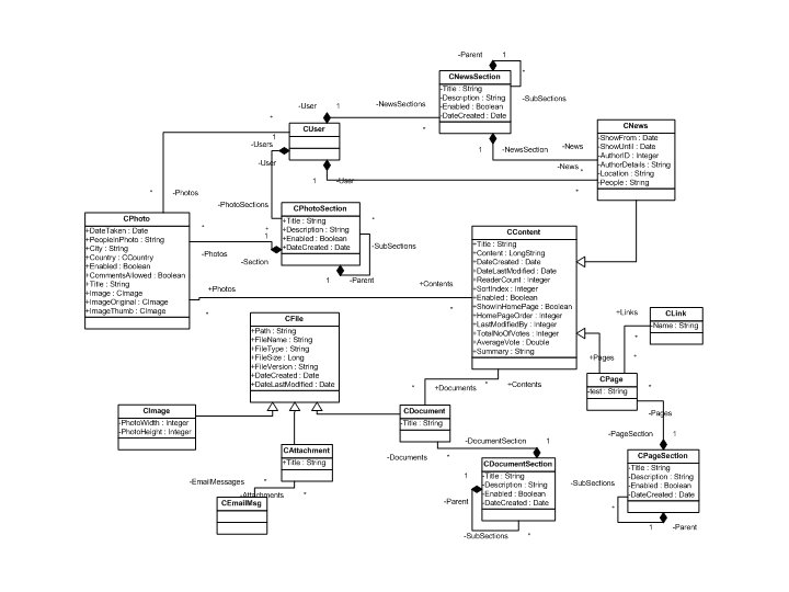
Class Diagram Example
Class Diagram Example Source: Booch et. al. , The UML User Guide