Crystals and Crystal Growing Why Single Crystals What


 6. Research: everything. Why? 7.")


 Hg. I 2, Cd. S,")

")


 W. G.")


 • Siemens process: high-purity silicon rods are exposed to")


- Slides: 22
Crystals and Crystal Growing
Why Single Crystals • What is a single crystal? • Single crystals cost a lot of money. • When and why is the cost justified? – Current semiconductor devices on an IC have characteristic dimensions of ¼ micron. – What happens if grain size is on the scale of microns? – What makes optical materials look translucent? – What happens when a “weapons grade laser beam” hits an inhomogeneity in an optical component?
Applications of Single Crystals For what applications are single crystals necessary? 1. Semiconductor optoelectronics (substrate materials) Transistors, diodes, integrated circuits: Si, Ge, Ga. As, In. P LEDs and lasers: Ga. As, Ga. In. P, Ga. As. P, Ga. P: N, ruby Solar cells: Si, Ga. As, Ga. In. P/Ga. As tandems Microwave sources: Ga. As 2. Non-glass optics (see previous lecture for transmission ranges): alkali halides, alkaline earth halides, thallium halides, Ge, sapphire 3. Electromechanical transducers Ultrasonic generators, sonar: ADP, KDP Strain gauges: Si Optical modulators: Li. Nb. O 3, Ba. Ti. O 3, Ba. Ni. O 3 Piezoelectric microphone sources: quartz 4. Radiation detectors: Hg. I 2, Na. I: Tl, Cs. I: Tl, Li. I: Eu, Si, Ge, III-V, II-VI, Pb. S
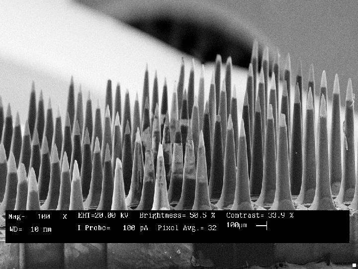
5. Micromechanical devices: Si Utah Neural Array (SEM image) 6. Research: everything. Why? 7. Artificial gems: sapphire, ruby, Ti. O 2, Zr. O 2 Why are they necessary for those applications? (Numbers correspond) 1. Electrical homogeneity on the length scale of the device; minimum carrier scattering 2. Optical homogeneity on the length scale of the light being transmitted; minimum light scattering 3. Mechanical strength and homogeneity; availability of processing technology: nickel-based super alloy turbine blades 4. Purity; well-defined material In all cases: optical, electronic or mechanical properties superior to nonsingle crystal competition.
Superconducting Ceramic Single Crystals Aps. org
Bulk Crystal Growth Techniques
Technique Examples Advantages Disadvantages Melt: ”Directional Solidification” Elemental & Compound semiconductors: Si, Ge, Ga. As, In. P FAST Large sizes possible Often energy intensive some materials decompose before melting Bridgman (horizontal/vertical) Cu. In. Se 2, MCT, Cd. Te, Zn. Se, Ga. Se Oxides-insulators: sapphire Reasonable Keff Seeded: predetermined orientation Crucible can be a problem Czochralski ("Cz") Windows: sapphire Scintillators: BGO, Cd. WO 4 NLO materials: Li. Nb. O 3, Cs. Li. B 6 O 10 Alkali scintillators-Cs. I: Tl Halides: windows-wide transmitting filters Always the technique of choice Dopants can be volatile Contamination
Technique Vapor Examples Physical vapor transport (evaporation & condensation) Hg. I 2, Cd. S, Zn. S, NH 4 X Hg 2 Cl 2, Cd. S Molecular Organics! Chemical vapor deposition (open flow) Refractories: Si. C, PBN Semiconductor epitaxy! Chemical vapor transport (closed system) Ti. O 2, Eu. S, "halogen lamps" Sn. O 2, In 2 S 3 Advantages Disadvantages Can be used with materials that decompose or have excessive vapor pressure at melting point or with destructive phase transitions or extremely high melting points or which react with containers. Materials must have reasonable vapor pressure at temperature where surface kinetics is adequate Typically slow Difficult to control Very slow; batch process Solution/Flux ADP, KDP, Refractories Hydrothermal quartz Diamond: 1450 C, 742 kpsi, Ni flux Proteins, Minerals, Mo 2 C High Tc superconductors; Bi. Sr. Ca. Cu. O Morton’s tablesalt Large sizes possible Potentially low cost, large scale Reduced temperature less container contamination Can be inexpensive Very slow Temperature control very important Keff often very small doping difficult
Digression on Segregation and Purification • Electronic materials are only interesting when doped • Carrier type: “n” • Dopant: “P” • “Res”: “ 1 -20 ohms”
Typical Numbers • On previous label, ρ = 1 -20 Ohm (presumably 120 Ω-cm) • As you know: σ = 1/ρ = ne μ • For silicon at 10 Ω-cm with μn = 1700 cm 2/V-sec • n. P = 3. 7 x 10¹⁴/cm 3 • n. Si = 2. 33 gm/cm 3) x(6. 02 x 1023 atoms/mole) ÷(28. 068 gm/mole) = 4. 997 x 1022 atoms per mole • n. P / n. Si = 7 x 10 -9 = 7 ppb! • Background impurity level must be small on this scale!
Segregation • Coefficient can be greater or less than unity • Nutrient volume is finite – Causes major problems with dopant uniformity – Can be resolved by adding dopant to melts during growth • Only works for K>1!
Origin of Segregation: Binary Phase Diagram W. G. Pfann, Zone Melting
Using Segregation for Purification: “Normal Freezing” n. b. : exactly the same process is used to grow large single crystals “from the melt”! W. G. Pfann, Zone Melting
Impurity Distribution after Normal Freezing W. G. Pfann, Zone Melting
Concept of Zone Refining W. G. Pfann, Zone Melting Molten zone of length l is passed through ingot of length L Also the process used to make “float zone silicon”
Impurity Distribution after Single Pass of Zone (Less efficient than normal freezing) W. G. Pfann, Zone Melting
Impurity Distribution from Multi-pass Zone Refining n. b. : k = 0. 9524, l/L = 0. 01 W. G. Pfann, Zone Melting
Take Away Lessons • Segregation of impurities/dopants is a fact that you must deal with as an aspect of materials preparation • Segregation can be used as part of an elegant purification process • Zone refining can be very effective for materials purification
Current Purification of Silicon (Wikipedia) • Siemens process: high-purity silicon rods are exposed to trichlorosilane at 1150 °C. The trichlorosilane gas decomposes and deposits additional silicon onto the rods, enlarging them: • 2 HSi. Cl 3 → Si + 2 HCl + Si. Cl 4 • Silicon produced from this and similar processes is called polycrystalline silicon. Polycrystalline silicon typically has impurity levels of less than 10− 9.
Czochralski Growth www. people. seas. harvard. edu Synthesis may or may not be part of growth Ga. As may be pre-synthesized or a premeasured quantity As may be bubbled through Ga metal Li H synthesized from Li and H 2 (or D 2 ) Typical sizes: Si - 12" φ, 200 kg charge; Ga. As - 4" φ We have grown from a 2 g melt of isotopically pure K 13 C 15 N Typical growth rates: cm/hr
Vertical Bridgman Technique Melting point isotherm is directionally translated through an ingot from a spatially confined region. Typically unseeded no seed necessary Can be seeded: quality as high as Czochralski High yield: all starting material is recovered as single crystal Diameters to 22 inches; 40 cm 2 square KDP Used extensively for alkali halide scintillators, transducers and windows