
Cryostat design Thermosyphon cooling Alexey Bragin Vassily Syrovatin
Cryostat design Thermosyphon cooling Alexey Bragin, Vassily Syrovatin Budker Institute of Nuclear Physics, Novosibirsk, Russia November 2019
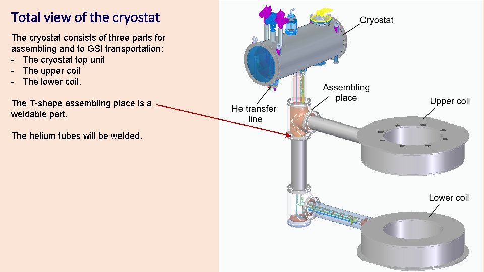
Total view of the cryostat The cryostat consists of three parts for assembling and to GSI transportation: - The cryostat top unit - The upper coil - The lower coil. The T-shape assembling place is a weldable part. The helium tubes will be welded.
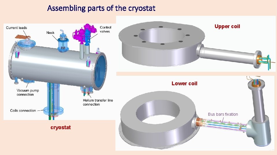
Assembling parts of the cryostat Upper coil Lower coil Bus bars fixation cryostat
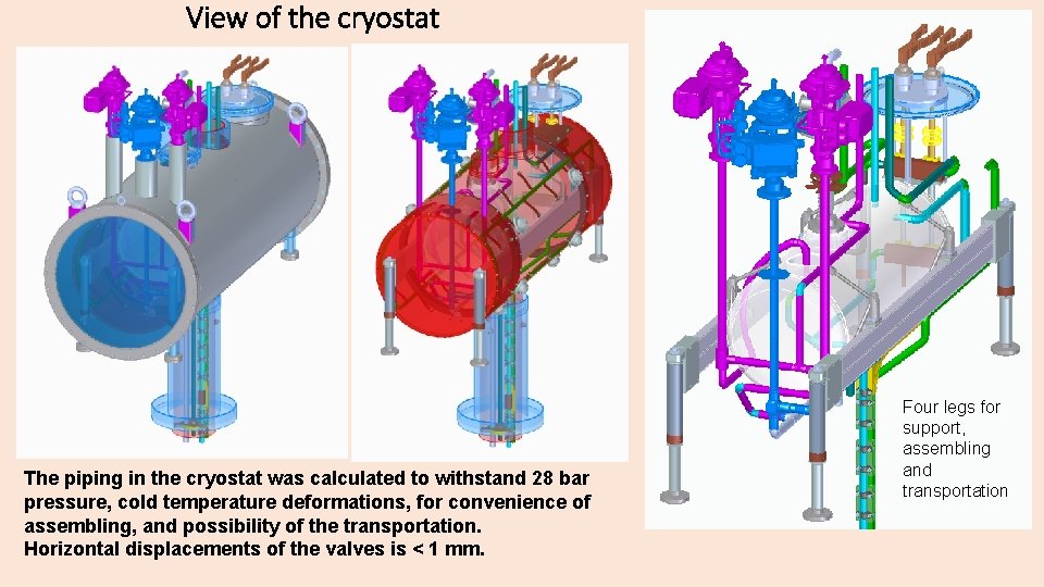
View of the cryostat The piping in the cryostat was calculated to withstand 28 bar pressure, cold temperature deformations, for convenience of assembling, and possibility of the transportation. Horizontal displacements of the valves is < 1 mm. Four legs for support, assembling and transportation
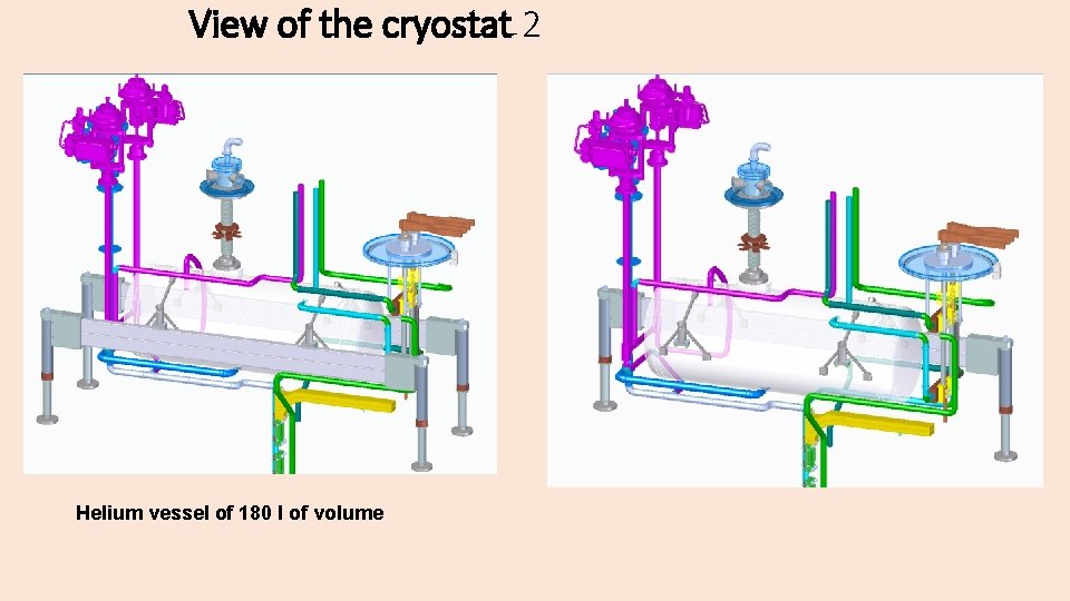
View of the cryostat 2 Helium vessel of 180 l of volume
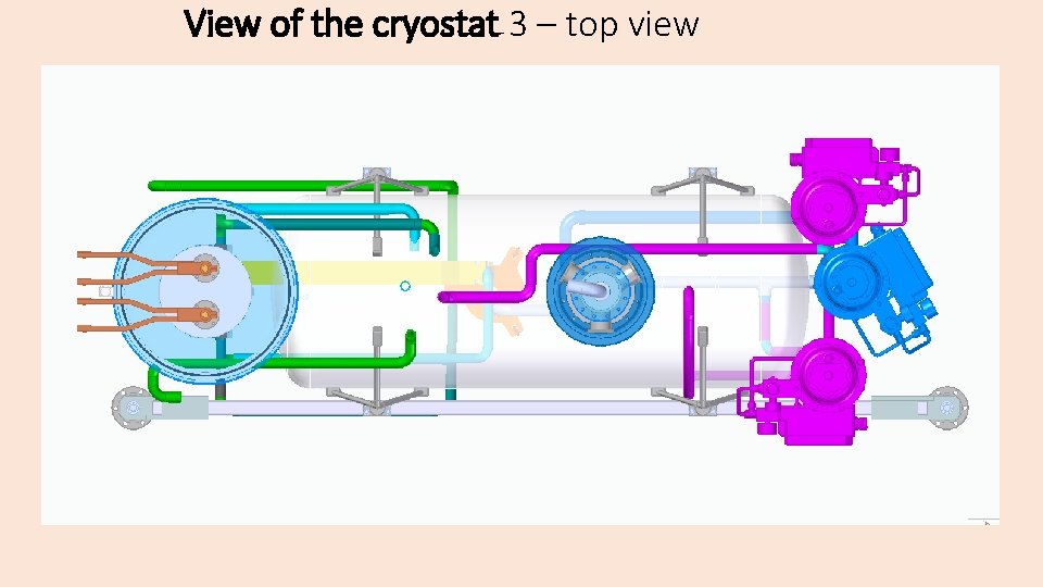
View of the cryostat 3 – top view
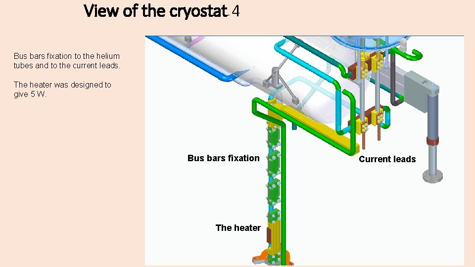
View of the cryostat 4 Bus bars fixation to the helium tubes and to the current leads. The heater was designed to give 5 W. Bus bars fixation The heater Current leads
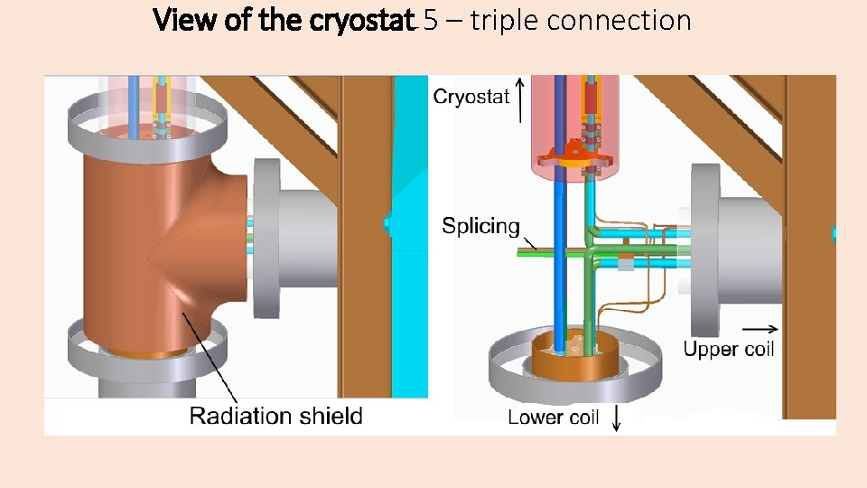
View of the cryostat 5 – triple connection Splicing
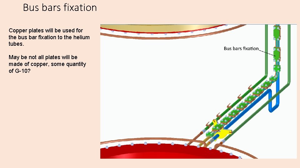
Bus bars fixation Copper plates will be used for the bus bar fixation to the helium tubes. May be not all plates will be made of copper, some quantity of G-10?
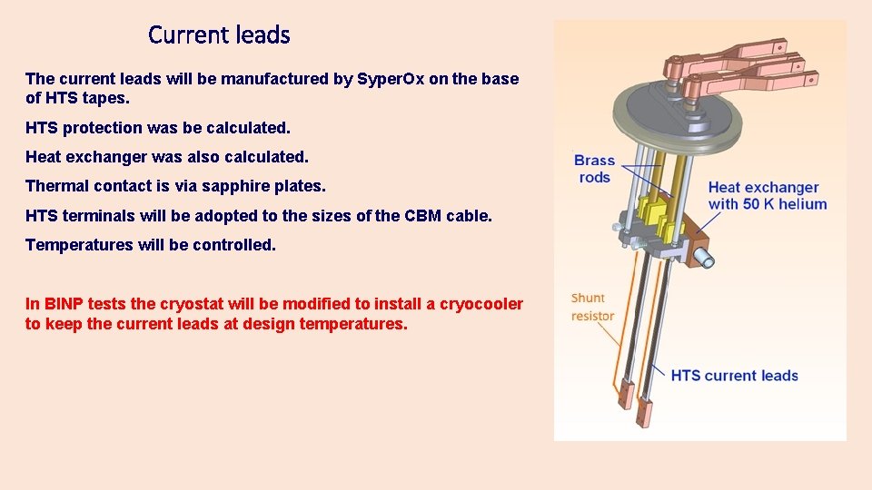
Current leads The current leads will be manufactured by Syper. Ox on the base of HTS tapes. HTS protection was be calculated. Heat exchanger was also calculated. Thermal contact is via sapphire plates. HTS terminals will be adopted to the sizes of the CBM cable. Temperatures will be controlled. In BINP tests the cryostat will be modified to install a cryocooler to keep the current leads at design temperatures.
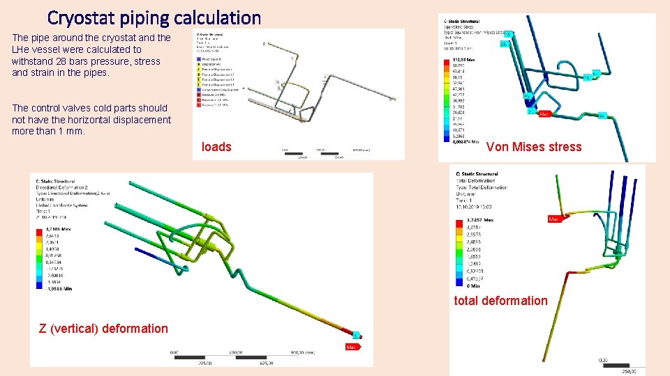
Cryostat piping calculation The pipe around the cryostat and the LHe vessel were calculated to withstand 28 bars pressure, stress and strain in the pipes. The control valves cold parts should not have the horizontal displacement more than 1 mm. loads Von Mises stress total deformation Z (vertical) deformation
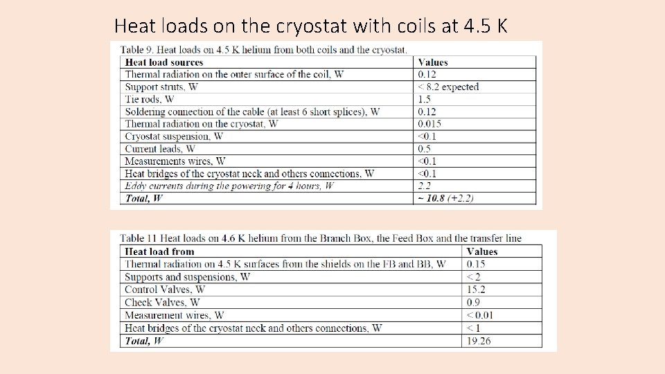
Heat loads on the cryostat with coils at 4. 5 K
Heat loads on the cryostat with coils at ~ 55 K
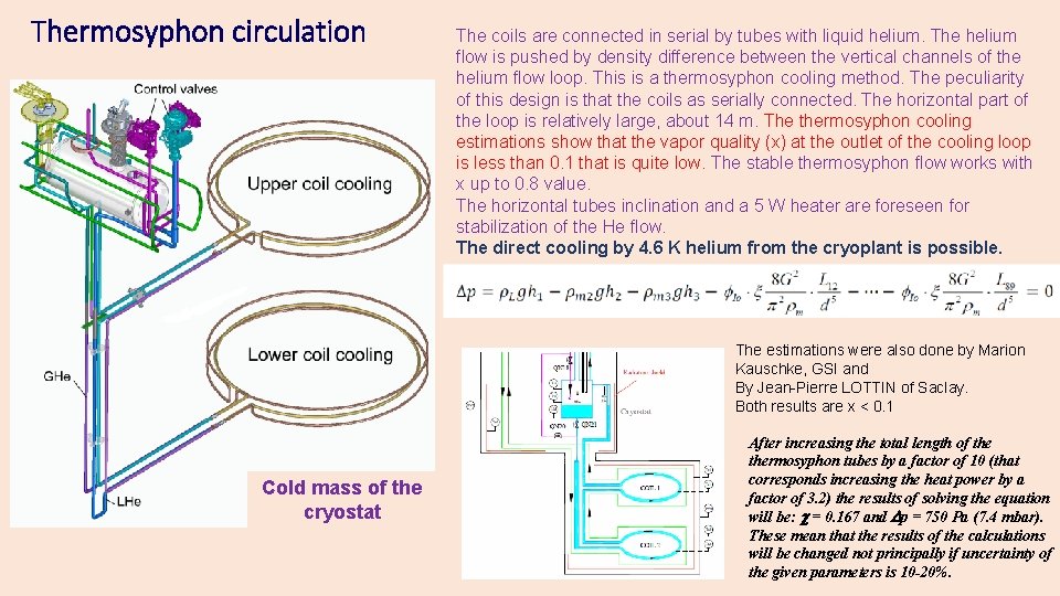
Thermosyphon circulation The coils are connected in serial by tubes with liquid helium. The helium flow is pushed by density difference between the vertical channels of the helium flow loop. This is a thermosyphon cooling method. The peculiarity of this design is that the coils as serially connected. The horizontal part of the loop is relatively large, about 14 m. The thermosyphon cooling estimations show that the vapor quality (x) at the outlet of the cooling loop is less than 0. 1 that is quite low. The stable thermosyphon flow works with x up to 0. 8 value. The horizontal tubes inclination and a 5 W heater are foreseen for stabilization of the He flow. The direct cooling by 4. 6 K helium from the cryoplant is possible. The estimations were also done by Marion Kauschke, GSI and By Jean-Pierre LOTTIN of Saclay. Both results are x < 0. 1 Cold mass of the cryostat After increasing the total length of thermosyphon tubes by a factor of 10 (that corresponds increasing the heat power by a factor of 3. 2) the results of solving the equation will be: = 0. 167 and p = 750 Pa (7. 4 mbar). These mean that the results of the calculations will be changed not principally if uncertainty of the given parameters is 10 -20%.
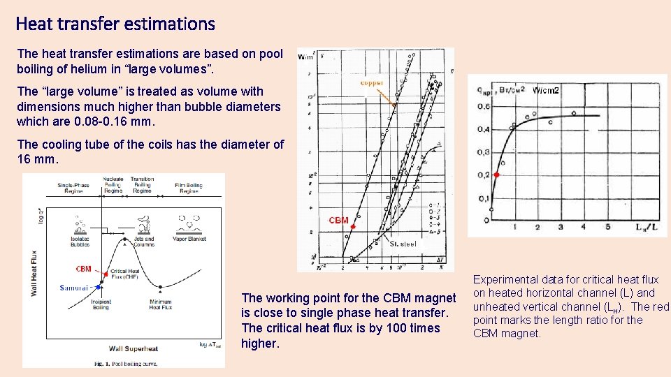
Heat transfer estimations The heat transfer estimations are based on pool boiling of helium in “large volumes”. The “large volume” is treated as volume with dimensions much higher than bubble diameters which are 0. 08 -0. 16 mm. The cooling tube of the coils has the diameter of 16 mm. The working point for the CBM magnet is close to single phase heat transfer. The critical heat flux is by 100 times higher. Experimental data for critical heat flux on heated horizontal channel (L) and unheated vertical channel (Lн). The red point marks the length ratio for the CBM magnet.
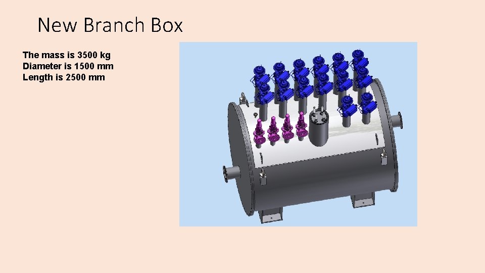
New Branch Box The mass is 3500 kg Diameter is 1500 mm Length is 2500 mm
Conclusions • The preliminary design of the cryostat is presented. • The heat loads are estimated. • The cryostat calculations were done. • The design of the HTS current leads is discussed in the quench calculations. • The thermosyphon evaluations are presented
- Slides: 17