Creative Innovation Series NGT506 Parking Radar NGT506 Parking


![Code Upload (1) Connects USB cable (3) Select Proper COM Port [COMx] (4) Press Code Upload (1) Connects USB cable (3) Select Proper COM Port [COMx] (4) Press](https://slidetodoc.com/presentation_image/93653b58ad423209c80ab1ba62188ef2/image-53.jpg)


- Slides: 65

Creative Innovation Series NGT-506 : Parking Radar

NGT-506 : Parking Radar Objective: Using Arduino, Ultrasonic Distance Sensor, Piezoelectric Buzzer, Self Lock Switch, Color Sticker to create a Parking Radar with alarm function. . Description: An Arduino based Parking Radar is created with an Ultrasonic Distance Sensor, a Piezoelectric Buzzer, a Self Lock Switch, and 4 Color Stickers. Ultrasonic Distance Sensor detects the distance between the wall and sensor and output the distance on four Color Stickers with of color LED numbers. The Self Lock Switch is used to turn on / off the buzzer alarm, which beeps rashly when the sensor is approaching the wall. Module List: 1. faya brick. Nano x 1 2. Ultrasonic Distance Sensor x 1 3. Piezoelectric Buzzer x 1 4. Self Lock Switch x 1 5. Color Sticker x 4

Hardware List 1. faya brick. Nano 2. Ultrasonic Distance Sensor 3. Self-Lock Switch 4. Piezoelectric Buzzer 5. Color Stickers x 4 6. Power Wire (Type B) 7. Power Wire (Type A) 8. Brick Post 9. Brick Cap 10. Signal Wires with a Capacitor 11. micro. USB Cable 12. Brick Set 13. Brick Plate x 2 14. Extra Bricks

1. faya brick. Nano 1. Compatible to Arduino Nano 2. Includes 4 brick holes to connect to bricks. 3. Includes 2 power heads to supply power to other faya modules 4. Use micro. USB interface

2. Ultrasonic Distance Sensor Trig Pin Echo Pin distance to leave wall distance to return 3 steps to calculate distance (1) Sending 10 us HIGH at Trig Pin (2) Detect HIGH TIME at ECHO pin (3) Distance (meater) = HIGH time × velocity of sound / 2 = HIGH time x (340 M/S) / 2

3. Self-Lock Switch UP location DOWN location (lock) When the button of Self-Lock Switch is pressed, it will lock at DOWN location. When press again, it will return to HIGH location. 1. PU Port : Button at UP location HIGH Button at DOWN location LOW 2. PD Port : Button at UP location LOW Button at DOWN location HIGH

4. Piezoelectric Buzzer 1. Input HIGH at Vin port Buzzer beeps 2. Input LOW at Vin port Buzzer mute 3. If mute is the default status, intput LOW at Vin at startup is required.

5. Color Sticker Din Dout Vcc Data Gnd Din 1. 2. 3. 4. 5. 6. 7. 8. Dout Din Dout Use 3 signal wires to cascade a longer Color Sticker. To control Color Sticker, library <Fast. LED. h> is required. Use CRGB class_name[NUM_LEDS] to define CRGB class Use Fast. LED. add. Leds<WS 2812 B, DATA_PIN, RGB>] to setup parameters. Function [. set. Brightness] is used to set brightness of all connected LEDs Function [CRGB(Red, Green, Blue)] is used to set each LED color with RGB mode. Function [CHSV(Hue, Saturation, Value)] is to set each LED color with HSV mode. Function [Fast. LED. show] is used to show LED with assigned color.

6. / 7. Power Wire Type A : Connector-to-Pins Type B : Connector-to-Connector Type B Type A 1. Power Wire is used to supply the power from one to another faya modules. Red Wire connects to Vcc and Black Wire connects to Gnd. 2. Above example shows that the power from Arduino is delivered to DC motor via Type A wire and delivered to other two modules via Type B wires.

8. Brick Post 1. Use brick post to interface faya modules with bricks. 2. Brick post is stackable, as shown in above pictures.

9. Brick Cap Cover the brick post with brick cap to prevent brick post loose from faya modules.

10. Signal Wires 1. Signal Wire is used to connect signals between Arduino and faya module pins. 2. The size of the signal wire is AWG 22

11. micro USB cable 1. Use micro USB cable to connect between faya brick. Nano and computer.

12. Brick Set Normal Type 1 x 1 : 12 pcs 1 x 2 : 12 pcs 1 x 3 : 12 pcs 1 x 4 : 12 pcs 2 x 2 : 8 pcs 2 x 3 : 12 pcs 2 x 4 : 24 pcs (at least) Plate Type 2 x 6 : 6 pcs 2 x 10 : 2 pcs 6 x 8 : 1 pcs 90 degree Type 1 x 1 : 10 pcs 1. LEGO brick compatible 2. Random color for each type 3. A bigger normal type brick maybe replaced by smaller brick for example, a 2 x 4 brick maybe replaced by 2 pcs of 2 x 2

13. Brick Plate 1. Use two Brick Plate as foundation of the project. 2. Plate Size : 16 x 16 3. Random Color

14. Extra Bricks 2 x 6 brick plate : 3 pcs 2 x 10 brick plate : 4 pcs 1. Use extra bricks to create a stronger bot 2. LEGO brick compatible 3. Random color

Assembling This section introduce the assemble of bricks and faya modules

Assemble Brick Post at board corners of each module.

Assemble Brick Cap Cover the Brick Cap on the top of Brick Post. This assembling prevents the brick post loosen from the modules.

Create Color Ruler (1/2) (1) Cascade four 2 x 10 brick plate (2) Assemble with three 2 x 6 brick plate at back (3) Cascade four Color Stickers on top of brick plate. See below for module direction and location.

Cascade Color Ruler (2/2) (4) Connect signal wires.

Assemble Brick Plate Combine two 16 x 16 brick plate with bricks shown abobe.

Assemble Front Bricks Create a structure as shown in the picture. This structure is used to place Ultrasonic Distance Sensor.

Assemble Modules Self-Lock Switch brick. Nano Ultrasonic Distance Sensor Piezoelectric Buzzer Assemble brick. Nano, Piezoelectric Sensor, Self. Lock Swith, and Ultrasonic Distance Sensor at corresponding locations shown in the picture.

Assemble Bricks (1 st Floor) Assemble 1 st floor bricks as shown in above locations.

Power Wire Connection (1/2) Use Type-B Power Wire to connect modules identical to above. brick. Nano Pizeoelectric Buzzer Piezoelectric Buzzer Ultrasonic Distance Sensor Self-Lock Switch

Assemble Bricks (2 nd Floor) Use three 2 x 4 bricks to create 2 nd floor as shown above.

Signal Wire Connection (1/4) brick. Nano_A 5 Piezoelectric Buzzer_Vin

Signal Wire Connection (2/4) brick. Nano_D 2 Self-Lock Switch_PU

Assemble Bricks (3 rd Floor) Use four 2 x 4 bricks to create 3 rd floor as shown above.

Signal Wire Connection (3/4) brick. Nano_D 11 Ultrasonic Distance Sensor_Echo brick. Nano_D 12 Ultrasonic Distance Sensor_Erig

Assemble Bricks (4 th Floor) Use three 2 x 4 bricks to create 4 th floor as shown above.

Assemble Bricks (5 th Floor) Use two 2 x 4 bricks and two 90 -degree bricks to create 5 th floor as shown above. Be aware of the direction of two 90 -degree bricks.

Assemble Bricks (6 th Floor) Put one 1 x 2 brick on the top of the 90 -degree bricks to complete 6 th floor.

Assemble Color Ruler Front View Back View Assemble color ruler to the main body through 90 degree bricks.

Power Wire Connection (2/2) Use Type-A Power Wire to connect power between brick. Nano and Color Sticker. Note that Red Wire must connect to VCC, and Black Wire must connect to GND.

Signal Wire Connection (4/4) brick. Nano_D 6 Color Sticker_Din

Note: Power and Signal Wires Use the hole between bricks to connect power and signal wires to the brick. Nano behind the brick wall.

Decorate Your Parking Radar We have created the structure for Parking Radar, you may use rest of bricks to decorate your Parking Radar.

Decoration Complete (front view)

Decoration Complete (side view)

Decoration Complete (back view)

Source Code Parking_Radar_1 E. ino https: //goo. gl/LCMLv. L Copy source code [Parking_radar_1 E. ino] to a folder named [FMRadio_1 E] Fast. LED Library https: //goo. gl/h 8 a 3 i 6 Unzip [fast. LED], and put in [Arduino / Libraries] Folder

Code Explanation (Main Loop) (1) (2)show. LED (3)out. Beeper L 42: Using Ultrasonic Distacne Sensor to detect distance between sensor and wall. L 44: Show the distance on the LED ruler. Shorter distance results in higher LED bar L 45: Show radar alarm. Shorter distance results in rush alarm. (1)get. Distance

Code Explanation (L 53~L 56) use pulse. In to measure this time L 53~L 55: To activate the ultrasonic distance sensor, it need a 10 us trigger pulse at Trigger pin. L 56: Use pulse. In function to detect the “Time it takes pulse to leave and return to sensor”. This time is the speed of sound (340 m/sec) travel from sensor to the wall and back to the sensor. As the result, the distance can be calculated: 1 cm 34000 cm/sec = 29 us to travel 1 cm Distance = pulse. In Time / 2 29 us = pulse. In Time 58 us

Code Explanation (L 51、57、60) i=0 i=1 i=2 i=3 i=4 distance distance total_Distance Average Distance = total_Distance 5 To minimum sensing error, it is common to measure the sensing data several times and calculate its average.

Code Explanation (L 69) Two ways to setup LED colors in fast. LED: (1) CRGB (R, G, B) (2) CHSV (H, S, V) all parameters are between 0~255 Faya_color. Sticker[ i ] = CHSV( H, S, V); Use HSV Mode to setup i_th LED.

Code Explanation (L 65~L 72) IF (distance >= 36 cm) All 32 LEDs turn OFF CHSV(0, 0, 0) >= 36 cm

Code Explanation (L 74~L 84) IF (distance < 36 cm) 35 cm = 1 LED on 31 off 34 cm = 2 LED on 30 off 33 cm = 3 LED on 29 off. . 6 cm = 30 LED on 2 off 5 cm = 31 LED on 1 off 4 cm = All LED on 0 off < 36 cm

Code Explanation (L 87~L 103) 8 cm Execute beeper() every 10 x 8 = 80 ms 23 cm Execute beeper() every 10 x 23 = 230 ms if(millis()-time > (int)(10*distance)) Short distance execute alarm beeps faster than long distance. (Rush alarm when approaching the wall)

Code Explanation (L 105~L 104) ALARM BEEP distance <= 5 cm LONG BEEP 30 cm >= distance > 5 cm ALARM BEEP distance >30 cm NO BEEP The beep period of the alarm beep is proportional to the detecting distance

Code Explanation (result table) distance led number buzzer 40 39 38 37 36 35 34 33 32 31 0 0 0 1 2 3 4 5 distance led number buzzer 30 29 28 27 26 25 24 23 22 21 6 7 8 9 10 11 12 13 14 15 distance led number buzzer 20 19 18 17 16 15 14 13 12 11 16 17 18 19 20 21 22 23 24 25 distance led number buzzer 10 9 8 7 6 5 4 3 2 1 26 27 28 29 30 31 32 32 NO BEEP ALARM BEEP LONG BEEP
![Code Upload 1 Connects USB cable 3 Select Proper COM Port COMx 4 Press Code Upload (1) Connects USB cable (3) Select Proper COM Port [COMx] (4) Press](https://slidetodoc.com/presentation_image/93653b58ad423209c80ab1ba62188ef2/image-53.jpg)
Code Upload (1) Connects USB cable (3) Select Proper COM Port [COMx] (4) Press [Upload] button (2) Select [Arduino Nano] (5) Done uploading

Testing your Parking Radar

Test your Parking Radar https: //youtu. be/ix. Vg 32 If 8 IE

Remove the Noise Arduino uses Fast. LED library to generates sequential signal to control Color Sticker. These sequential signal will interfere buzzer through system ground, resulting in noisy sound at Buzzer. To reduce this noise, you may add a 220 u. F capacitor between 5 V and GND, as shown in above picture.

After adding a Capacitor https: //youtu. be/QFCr 8 Ny. R 08 E

Final Result https: //youtu. be/Brq. Aj. UJjsno

Appendix A : Arduino Installation (1) Visit (www. arduino. cc) and click SOFTWARE (2) Save file in your computer and follow the instructions to install Arduino IDE in your computer https: //www. arduino. cc/en/Guide/Windows

Appendix B : brick. Nano Installation (1/3) (1) Connect brick. Nano to Windows PC with micro. USB cable (2) Windows should search device and install the device driver automatically. When success, A [USB Serial Port (COMx)] should and list it in Device Manager.

Appendix B : brick. Nano Installation (2/3) (3) If windows does not install the driver automatically, please install the driver manually. (3 -1) Right click and select Properties (3 -3) Browse my computer for driver software (3 -4) Browse folder [Arduino/drivers/FTDI USB Drivers] to complete the driver installation. (3 -2) Update Driver

Appendix B : brick. Nano Installation (3/3) (4) When driver installed successfully, the device manager and Arduino IDE should appear the COM Port number for brick. Nano.

Appendix C : Trouble Shooting The default processor firmware is built with ATmega 328 B (Old Bootloader). If you encounter a problem during upload, change the Bootloader to upper one (ATmega 328 P) may help.

Reference Getting Started with Arduino https: //www. arduino. cc/en/Guide/Home. Page Arduino Tutorial https: //www. arduino. cc/en/Tutorial/Home. Page Arduino Programming Language Reference https: //www. arduino. cc/reference/en/ Arduino Playground http: //playground. arduino. cc/ fayalab Module specification and sample code http: //www. kandh. com. tw/products_1. php? gid=33

Technical Support contact us at fayalab@kandh. com. tw K&H MFG CO. , LTD. 5 F. , No. 8, Sec. 4, Ziqiang Rd. , Sanchong Dist. , New Taipei City 241, Taiwan R. O. C. TEL: 886 -2 -2286 -0700 FAX: 886 -2 -2287 -3066 E-Mail:education@kandh. com. tw WEB:http: //www. kandh. com. tw
 Mti and pulse doppler radar
 Mti versus pulse doppler radar
 Mysite.socccd
 Radical innovation vs disruptive innovation
 Voltage shunt feedback amplifier forms
 Serie de taylor
 Series aiding and series opposing
 Taylor frederick
 Arithmetic series formula
 Maclaurin series vs taylor series
 Ibm p series models
 Balmer series lyman series
 How is the weather in spring?
 Civil engineering applications of ground penetrating radar
 Radar dwell time
 Vrm radar
 Stalker radar trailer
 Cotrec
 Neteofrance
 Chuva on line
 Monopulse tracking radar
 Ott radar
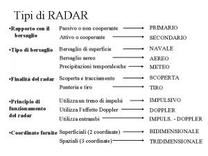
 Tipi di radar
 Agility health assessment
 Drdf aviation
 Doppler radar pensacola
 Cinematica radar
 Radar transportadora
 Radar aemet regional
 Redemet radar
 Enem 1999 um sistema de radar
 Synthetic radar aperture tutorial
 Radar
Radar Malware radar
 Radar logika
 Constant altitude plan position indicator
 Bainbridge radar
 Cinematica radar
 Republic hydrometeorological institute of serbia
 Radar evaluating sources
 Radar transmitter
 Radar stands for radio detection and
 Radar landrienne
 Auckland rain radar
 Nrot radar
 Radar ranging
 Shmu radar maly javornik
 Radar 101
 Introduction to radar systems 3rd edition pdf
 Bmdr radar
 Bouřka
 Munich weather radar
 Exeter radar
 Radar tracking system
 Downburst brno
 Bojan lipovščak
 Scott afb weather radar
 Weather radar transceiver
 Hf radar
 Team radar retro
 Radar
Radar Weaher radar
 Satellite radar
 Urad radar
 Conical scan tracking radar block diagram
 Software encompasses
