CPU ARCHITECTURE OF ARM 9 PROCESSOR ABHIJITH P

CPU ARCHITECTURE OF ARM 9 PROCESSOR ABHIJITH P A ROLL NO. 1 S 6 ECE
 • The ARM 9 TDMI is a member of ARM")
ARM ARCHITECTURE (ARM 9) • The ARM 9 TDMI is a member of ARM family of general purpose microprocessors. • The ARM 9 TDMI is targeted at embedded control applications where high performance, low die size and low power are all important. • The ARM 9 TDMI supports both the 32 -bit ARM and 16 -bit Thumb instruction sets, allowing the user to trade off between high performance and high code density. • The ARM 9 TDMI supports the ARM debug architecture and includes logic to assist in both hardware and software debug. • The ARM 9 TDMI supports both bidirectional and unidirectional connection to external memory systems.

• The ARM 9 TDMI also includes support for coprocessors. • The ARM 9 TDMI processor core is implemented using a five-stage pipeline consisting of fetch, decode, execute, memory and write stages. • The device has a Harvard architecture, and the simple bus interface eases connection to either a cached or SRAM-based memory system.


MAIN PARTS OF ARM PROCESSOR • Register file: The processor has a total of 37 registers made up of 31 general 32 bit registers and 6 status registers. • Booth Multiplier. • Barrel Shifter • Arithmetic Logic Unit. • Control Unit

1. REGSTERS • The processor has a total of 37 registers made up of 31 general 32 bit registers and 6 status registers. • At any one time 6 general registers (R 0 to R 15) and one or two status registers are visible to the programmer. • The visible registers depend on the processor mode. • In all modes 16 registers, R 0 to R 15, are directly accessible. All registers except R 15 are general purpose and may be used to hold data or address values. Register R 15 holds the Program Counter(PC).
 is also accessible.")
• A seventeenth register (the CPSR- Current Program Status Register) is also accessible. It contains condition code flags and the current mode bita and may be thought of as an extension to the PC. • R 14 is used as the subroutine link register and receives a copy of R 15 when a Branch and link instruction is executed. • Program status register contains the processor flags (Z, S, V and C). • The mode bits also exist in the program status register in addition to the interrupt and fast interrupt disable bits. • Some special registers: Some registers are used like the instruction register, memory data read and write register and memory address register.

2. BARREL SHIFTER • The barrel shifter has a 32 bit input to be shifted. • This input is coming from the register file or it could be immediate data. • The shifter has other control inputs coming from instruction register. • Shift field in the instruction controls the operation of the barrel shifter. • This field indicates the type of shift to e performed (logical left or right, arithmetic right or rotate right) • The amount by which the register should be shifted is contained in an immediate field in the instruction or it could be the lower 6 bits of a register in the register file.

3. BOOTH MULTIPLIER • The multiplier has three 32 -bit inputs. • All the inputs come from the register file. • The multiplier output is only the 32 least significant bits of the product.
 • The ALU has two 32 -bit inputs. • The")
4. ARITHMETIC LOGIC UNIT(ALU) • The ALU has two 32 -bit inputs. • The first comes from the register file while the other comes from the shifter • ALU outputs modify the status register flags.

5. CONTROL UNIT • For any microprocessor, control unit is the heart of the system. • It is responsible for the system operation and so the control unit design is the most important part in the whole design. • Control unit is usually a pure combinational circuit. • The processor timing is also included in the control unit.

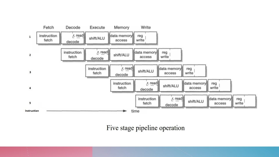
PIPELINE IMPLEMENTATION • The ARM 9 TDMI implementation uses a five-stage pipeline design. These five stages are: 1. Instruction fetch(F) 2. Instruction decode(D) 3. Execute(E) 4. Data memory access(M) 5. Register write(W)

THANK YOU
- Slides: 14