CPS 120 Introduction to Computer Science Midterm Exam


 • An XOR gate produces 1 if one")


 – 7 -bit code")


- Slides: 63
CPS 120: Introduction to Computer Science Midterm Exam Review
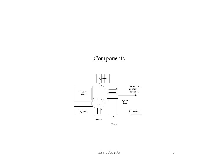
Introduction To Computers
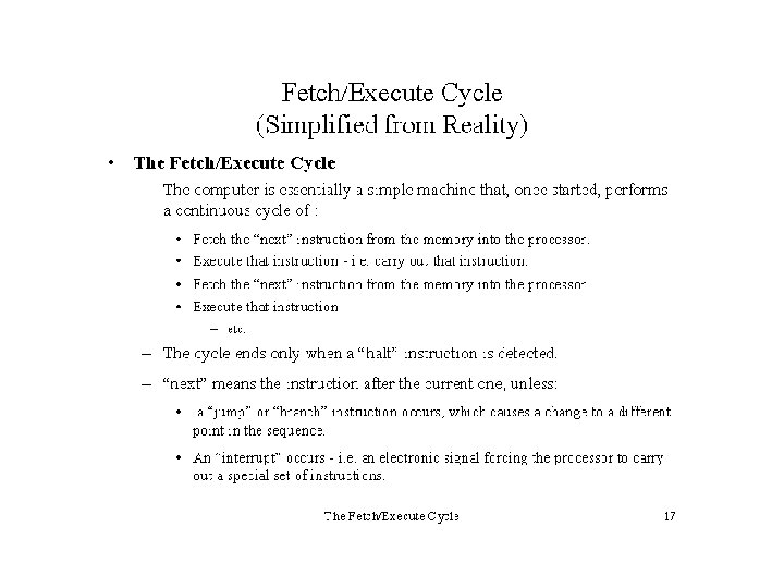
Machine Language • Every processor type has its own set of specific machine instructions • The relationship between the processor and the instructions it can carry out is completely integrated • Each machine-language instruction does only one very low-level task
Assembly Language • Assembly languages: assign mnemonic letter codes to each machine-language instruction – The programmer uses these letter codes in place of binary digits – A program called an assembler reads each of the instructions in mnemonic form and translates it into the machine-language equivalent
Instruction Format Difference between immediate-mode and direct-mode addressing
Some Sample Instructions Subset of Pep/7 instructions
Figure 7. 5 Assembly Process
Algorithm and Program Design
Top-Down Design An example of top-down design • This process continues for as many levels as it takes to expand every task to the smallest details • A step that needs to be expanded is an abstract step
A General Example • Planning a large party Subdividing the party planning
Flowchart • A graphical representation of an algorithm.
Pseudocode • Uses a mixture of English and formatting to make the steps in the solution explicit
Logic Flowcharts • These represent the flow of logic in a program and help programmers “see” program design.
Common Flowchart Symbols Terminator. Shows the starting and ending points of the program. A terminator has flow lines in only one direction, either in (a stop node) or out (a start node). Data Input or Output. Allows the user to input data and results to be displayed. Processing. Indicates an operation performed by the computer, such as a variable assignment or mathematical operation. With a heading – an internal subroutine Decision. The diamond indicates a decision structure. A diamond always has two flow lines out. One flow lineout is labeled the “yes” branch and the other is labeled the “no” branch. Predefined Process. One statement denotes a group of previously defined statements. Such as a function or a subroutine created externally Connectors avoid crossing flow lines, making the flowchart easier to read. Connectors indicate where flow lines are connected. Connectors come in pairs, one with a flow line in and the other with a flow line out. Off-page connector. Even fairly small programs can have flowcharts that extend several pages. The off-page connector indicates the continuation of the flowchart on another page. Just like connectors, off-page connectors come in pairs. Flow lines connect the flowchart symbols and show the sequence of operations during the program execution.
How to Draw a Flowchart • There are no hard and fast rules for constructing flowcharts, but there are guidelines which are useful to bear in mind. Here are six steps which can be used as a guide for completing flowcharts. 1. 2. 3. 4. 5. 6. Describe the purpose of the program to be created (this is a oneline statement) Start with a 'trigger' event (it may be the beginning of the program) Initialize any values that need to be defined at the start of the program Note each successive action concisely and clearly Go with the main flow (put extra detail in other charts -- this is the basis of structured programming) Follow the process through to a useful conclusion (end at a 'target' point -- like having no more records to process)
Pseudocode for a Generalized Program START Intialize variables LOOP While More records do READ record PROCESS record PRINT detail record ENDLOOP CALCULATE TOTALS PRINT total record END
Rules for Pseudocode 1. Make the pseudocode language-independent 2. Indent lines for readability 3. Make key words stick out by showing them capitalized, in a different color or a different font 4. Punctuation is optional 5. End every IF with ENDIF 6. Begin loop with LOOP and end with ENDLOOP 7. Show MAINLINE first; all others follow 8. TERMINATE all routines with an END instruction
Gates and Boolean Logic
Gates • Six types of gates – NOT – AND – OR – XOR – NAND – NOR
NOT Gate • A NOT gate accepts one input value and produces one output value Various representations of a NOT gate
NOT Gate • By definition, if the input value for a NOT gate is 0, the output value is 1, and if the input value is 1, the output is 0
AND Gate • An AND gate accepts two input signals • If the two input values for an AND gate are both 1, the output is 1; otherwise, the output is 0 Various representations of an AND gate
OR Gate • If the two input values are both 0, the output value is 0; otherwise, the output is 1 Figure 4. 3 Various representations of a OR gate
XOR Gate • XOR, or exclusive OR, gate – An XOR gate produces 0 if its two inputs are the same, and a 1 otherwise – Note the difference between the XOR gate and the OR gate; they differ only in one input situation – When both input signals are 1, the OR gate produces a 1 and the XOR produces a 0
XOR Gate Various representations of an XOR gate
NAND and NOR Gates • The NAND and NOR gates are essentially the opposite of the AND and OR gates, respectively Various representations of a NAND gate Various representations of a NOR gate
Review of Gate Processing • A NOT gate inverts its single input value • An AND gate produces 1 if both input values are 1 • An OR gate produces 1 if one or the other or both input values are 1
Review of Gate Processing (cont. ) • An XOR gate produces 1 if one or the other (but not both) input values are 1 • A NAND gate produces the opposite results of an AND gate • A NOR gate produces the opposite results of an OR gate
Adders • At the digital logic level, addition is performed in binary • Addition operations are carried out by special circuits called, appropriately, adders
Adders • The result of adding two binary digits could produce a carry value • Recall that 1 + 1 = 10 in base two • A circuit that computes the sum of two bits and produces the correct carry bit is called a half adder
Adders • Circuit diagram representing a half adder • Two Boolean expressions: sum = A B carry = AB Page 103
Adders • A circuit called a full adder takes the carryin value into account A full adder
Computer Mathematics
Representing Data • The computer knows the type of data stored in a particular location from the context in which the data are being used; – i. e. individual bytes, a word, a longword, etc – 01100011 01100101 01000000 • • Bytes: 99(10, 101 (10, 68 (10, 64(10 Two byte words: 24, 445 (10 and 17, 472 (10 Longword: 1, 667, 580, 992 (10 ASCII: c, e, D, @
Alphanumeric Codes • American Standard Code for Information Interchange (ASCII) – 7 -bit code – Since the unit of storage is a bit, all ASCII codes are represented by 8 bits, with a zero in the most significant digit H e l l o W o r l d 48 65 6 C 6 C 6 F 20 57 6 F 72 6 C 64 • ASCII is a subset of the Unicode character set
Decimal Equivalents • Assuming the bits are unsigned, the decimal value represented by the bits of a byte can be calculated as follows: 1. Number the bits beginning on the right using superscripts beginning with 0 and increasing as you move left • Note: 20, by definition is 1 2. Use each superscript as an exponent of a power of 2 3. Multiply the value of each bit by its corresponding power of 2 4. Add the products obtained
Binary to Hex • Step 1: Form four-bit groups beginning from the rightmost bit of the binary number – If the last group (at the leftmost position) has less than four bits, add extra zeros to the left of the group to make it a four-bit group • 011001111010100111 becomes • 0001 1110 1010 0111 • Step 2: Replace each four-bit group by its hexadecimal equivalent – 19 EAA 7(16 • Note: Octal is done in groups of threes
Converting Decimal to Other Bases • Step 1: Divide the number by the base you are converting to (r) • Step 2: Successively divide the quotients by (r) until a zero quotient is obtained • Step 3: The decimal equivalent is obtained by writing the remainders of the successive division in the opposite order in which they were obtained – Know as modulus arithmetic • Step 4: Verify the result by multiplying it out
Representing Signed Numbers • Remember, all numeric data is represented inside the computer as 1 s and 0 s – Arithmetic operations, particularly subtraction raise the possibility that the result might be negative • Any numerical convention needs to differentiate two basic elements of any given number, its sign and its magnitude – Conventions • Sign-magnitude • Two’s complement • One’s complement
Representing Negatives • It is necessary to choose one of the bits of the “basic unit” as a sign bit – Usually the leftmost bit – By convention, 0 is positive and 1 is negative • Positive values have the same representation in all conventions • However, in order to interpret the content of any memory location correctly, it necessary to know the convention being used for negative numbers
Sign-Magnitude • For a basic unit of N bits, the leftmost bit is used exclusively to represent the sign • The remaining (N-1) bits are used for the magnitude
Sign-magnitude Operations • Addition of two numbers in sign-magnitude is carried out using the usual conventions of binary arithmetic – If both numbers are the same sign, we add their magnitude and copy the same sign – If different signs, determine which number has the larger magnitude and subtract the other from it. The sign of the result is the sign of the operand with the larger magnitude
One’s Complement • Devised to make the addition of two numbers with different signs the same as two numbers with the same sign • Positive numbers are represented in the usual way • For negatives – STEP 1: Start with the binary representation of the absolute value – STEP 2: Complement all of its bits
One's Complement Operations – Treat the sign bit as any other bit – For addition, carry out of the leftmost bit is added to the rightmost bit – end-around carry
Two’s Complement Convention • • A positive number is represented using a procedure similar to sign-magnitude To express a negative number 1. 2. 3. – – Express the absolute value of the number in binary Change all the zeros to ones and all the ones to zeros (called “complementing the bits”) Add one to the number obtained in Step 2 The range of negative numbers is one larger than the range of positive numbers Given a negative number, to find its positive counterpart, use steps 2 & 3 above
Two’s Complement Operations • Addition: – Treat the numbers as unsigned integers • The sign bit is treated as any other number – Ignore any carry on the leftmost position • Subtraction – Treat the numbers as unsigned integers – If a "borrow" is necessary in the leftmost place, borrow as if there were another “invisible” onebit to the left of the minuend