
Cpr E 281 Digital Logic Instructor Alexander Stoytchev


- Slides: 119
Cpr. E 281: Digital Logic Instructor: Alexander Stoytchev http: //www. ece. iastate. edu/~alexs/classes/
Designing a Counter (Using the Sequential Circuit Approach) Cpr. E 281: Digital Logic Iowa State University, Ames, IA Copyright © Alexander Stoytchev
Example: Implement a modulo-8 counter
Mini Review
Asynchronous Counters
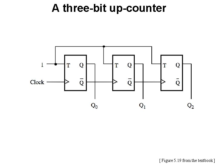
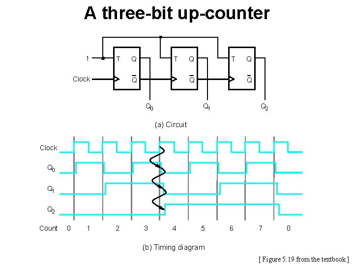
A three-bit up-counter [ Figure 5. 19 from the textbook ]
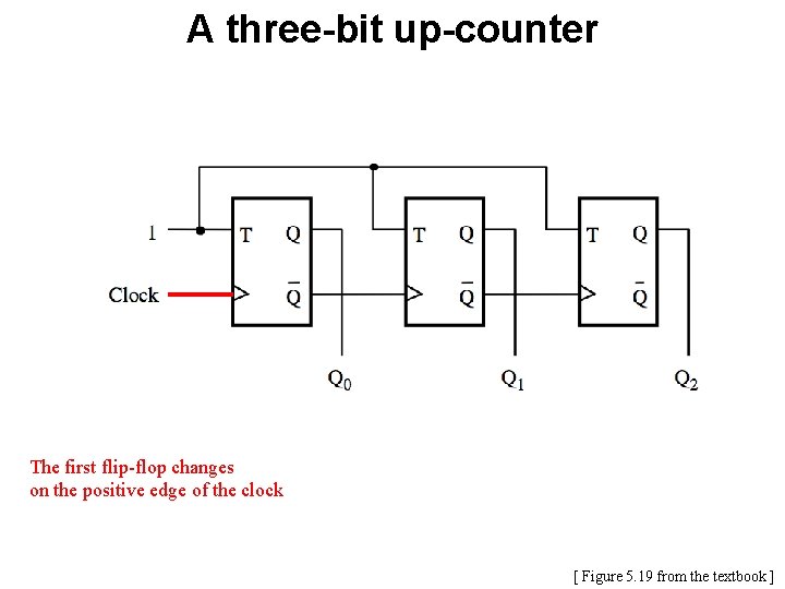
A three-bit up-counter The first flip-flop changes on the positive edge of the clock [ Figure 5. 19 from the textbook ]
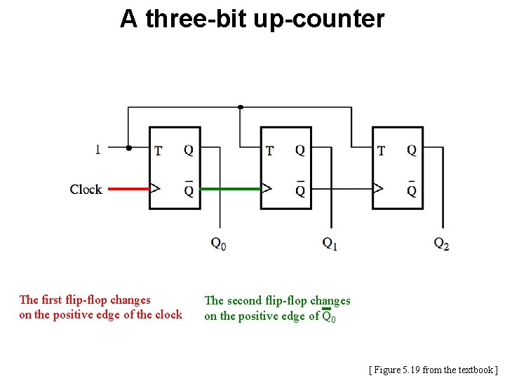
A three-bit up-counter The first flip-flop changes on the positive edge of the clock The second flip-flop changes on the positive edge of Q 0 [ Figure 5. 19 from the textbook ]
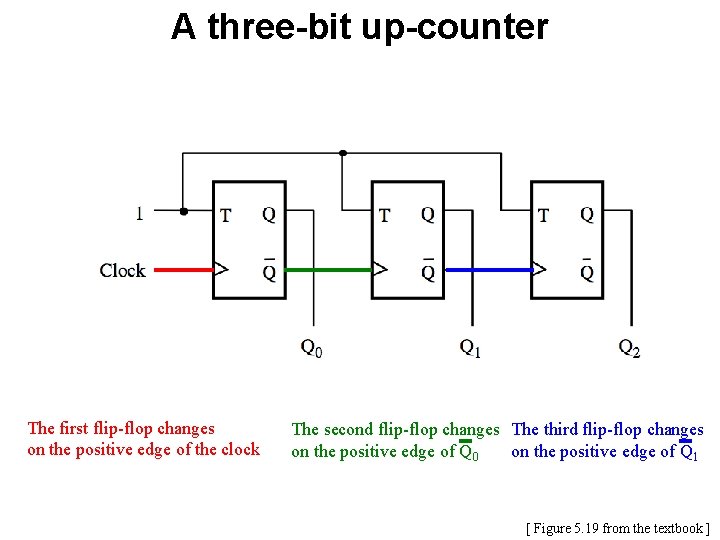
A three-bit up-counter The first flip-flop changes on the positive edge of the clock The second flip-flop changes The third flip-flop changes on the positive edge of Q 0 on the positive edge of Q 1 [ Figure 5. 19 from the textbook ]
A three-bit up-counter 1 T Clock Q T Q Q 0 Q Q Q 1 Q 2 (a) Circuit Clock Q 0 Q 1 Q 2 Count 0 1 2 3 4 5 6 7 0 (b) Timing diagram [ Figure 5. 19 from the textbook ]
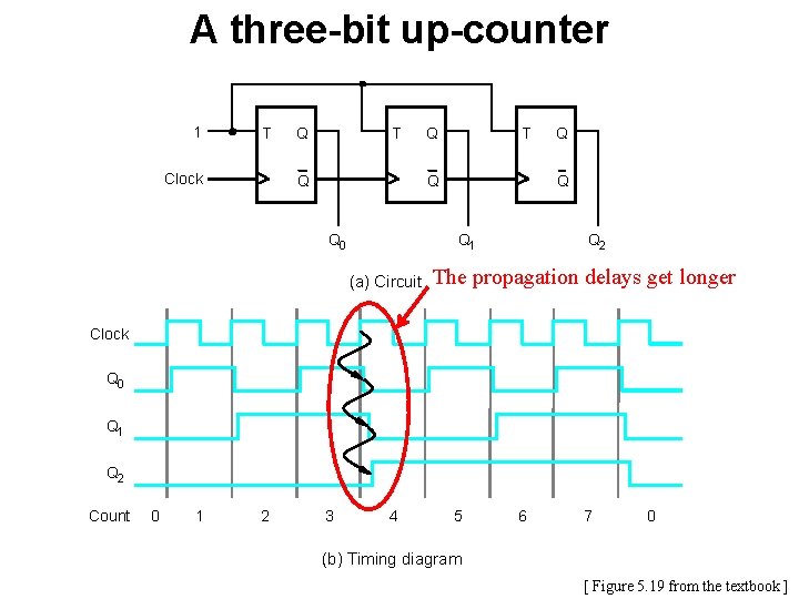
A three-bit up-counter 1 T Clock Q T Q Q 0 Q Q 1 (a) Circuit Q Q 2 The propagation delays get longer Clock Q 0 Q 1 Q 2 Count 0 1 2 3 4 5 6 7 0 (b) Timing diagram [ Figure 5. 19 from the textbook ]
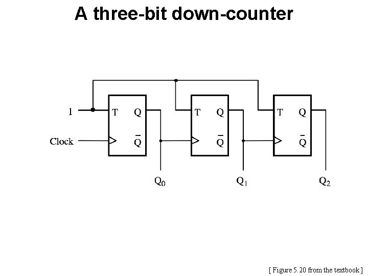
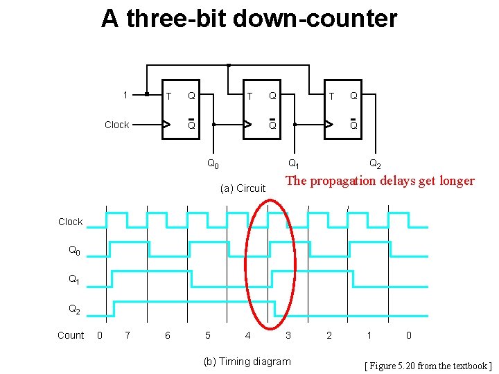
A three-bit down-counter [ Figure 5. 20 from the textbook ]
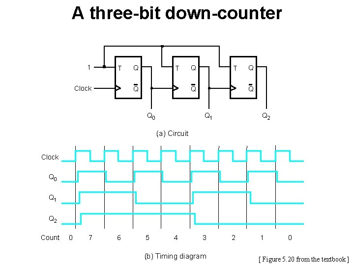
A three-bit down-counter 1 T Clock Q T Q Q 0 Q Q Q 1 Q 2 (a) Circuit Clock Q 0 Q 1 Q 2 Count 0 7 6 5 4 3 (b) Timing diagram 2 1 0 [ Figure 5. 20 from the textbook ]
A three-bit down-counter 1 T Clock Q T Q Q 0 Q Q 1 (a) Circuit Q Q 2 The propagation delays get longer Clock Q 0 Q 1 Q 2 Count 0 7 6 5 4 3 (b) Timing diagram 2 1 0 [ Figure 5. 20 from the textbook ]
Synchronous Counters
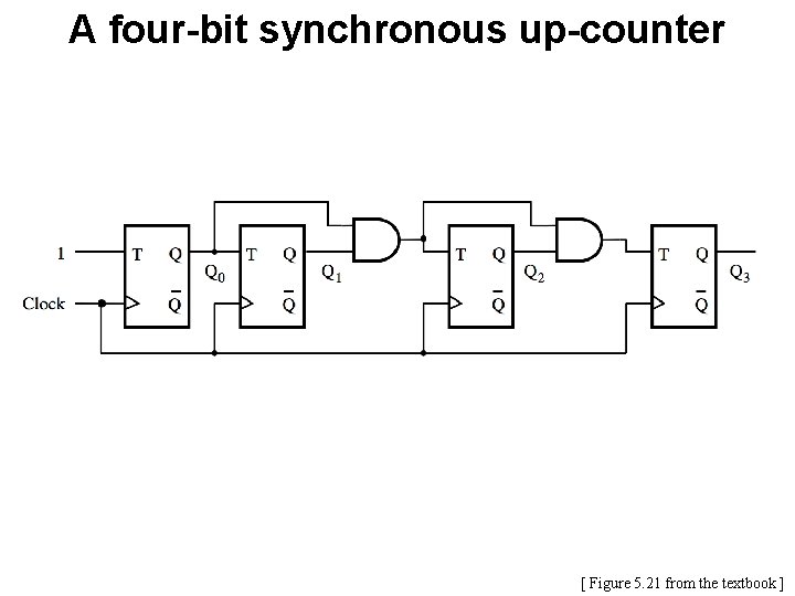
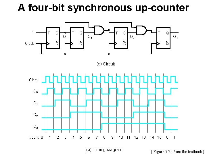
A four-bit synchronous up-counter [ Figure 5. 21 from the textbook ]
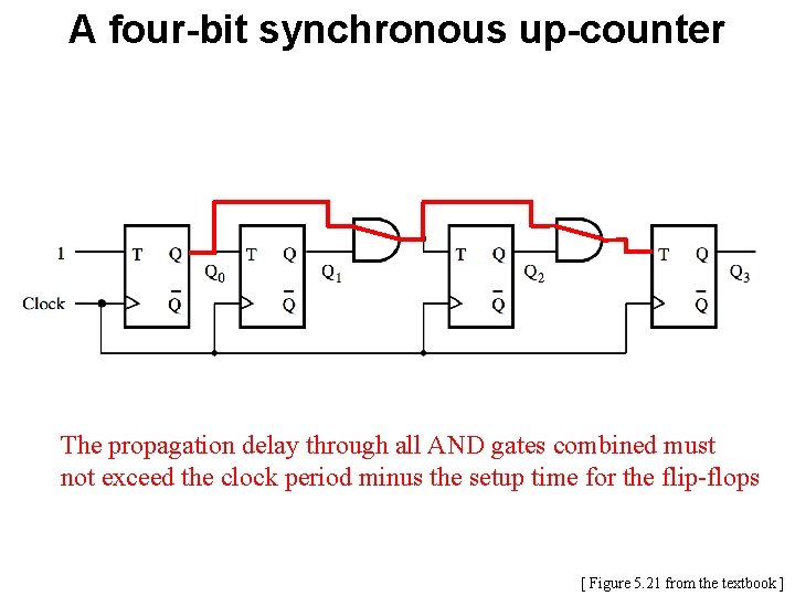
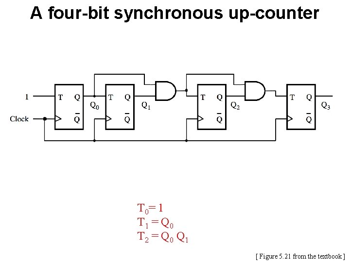
A four-bit synchronous up-counter The propagation delay through all AND gates combined must not exceed the clock period minus the setup time for the flip-flops [ Figure 5. 21 from the textbook ]
A four-bit synchronous up-counter 1 T Clock Q Q 0 T Q Q Q T Q 1 Q Q 2 T Q Q Q 3 Q (a) Circuit Clock Q 0 Q 1 Q 2 Q 3 Count 0 1 2 3 4 5 6 7 8 9 10 11 12 13 (b) Timing diagram 14 15 0 1 [ Figure 5. 21 from the textbook ]
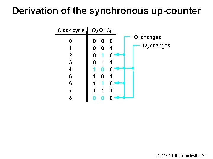
Derivation of the synchronous up-counter Clock cycle 0 1 2 3 4 5 6 7 8 Q 2 Q 1 Q 0 0 0 1 1 0 0 1 0 1 0 Q 1 changes Q 2 changes [ Table 5. 1 from the textbook ]
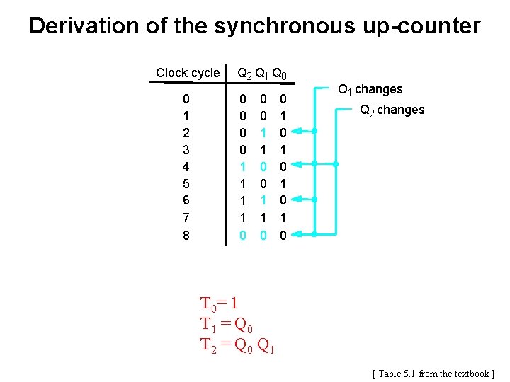
Derivation of the synchronous up-counter Clock cycle 0 1 2 3 4 5 6 7 8 Q 2 Q 1 Q 0 0 0 1 1 0 0 1 0 1 0 Q 1 changes Q 2 changes T 0= 1 T 1 = Q 0 T 2 = Q 0 Q 1 [ Table 5. 1 from the textbook ]
A four-bit synchronous up-counter T 0= 1 T 1 = Q 0 T 2 = Q 0 Q 1 [ Figure 5. 21 from the textbook ]
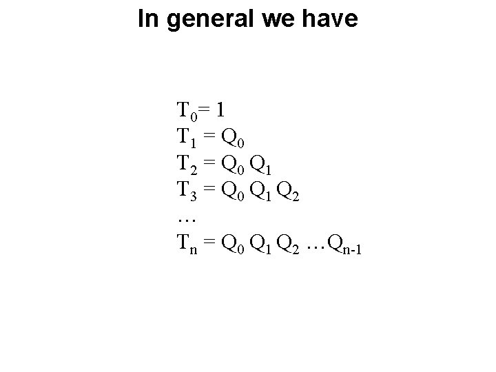
In general we have T 0= 1 T 1 = Q 0 T 2 = Q 0 Q 1 T 3 = Q 0 Q 1 Q 2 … Tn = Q 0 Q 1 Q 2 …Qn-1
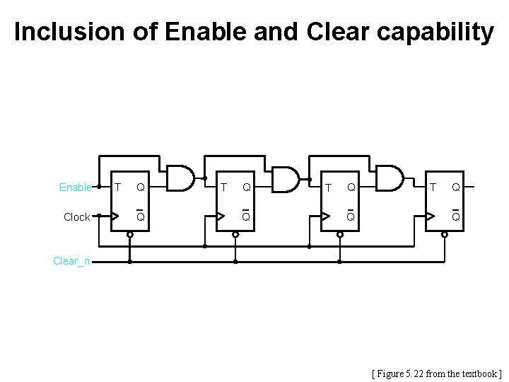
Inclusion of Enable and Clear capability Enable Clock T Q Q Clear_n [ Figure 5. 22 from the textbook ]
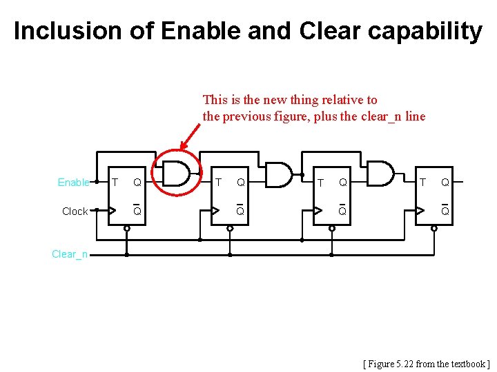
Inclusion of Enable and Clear capability This is the new thing relative to the previous figure, plus the clear_n line Enable Clock T Q Q Clear_n [ Figure 5. 22 from the textbook ]
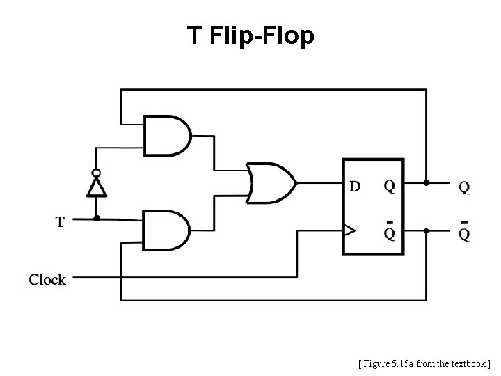
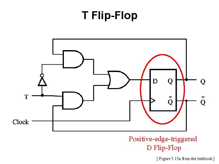
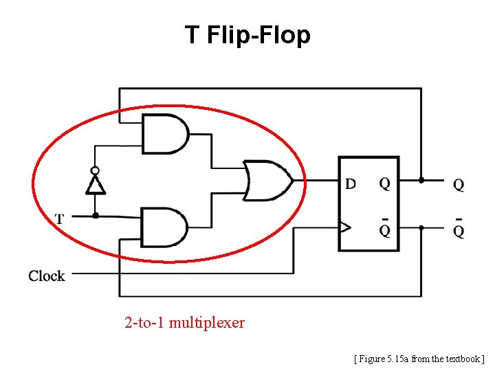
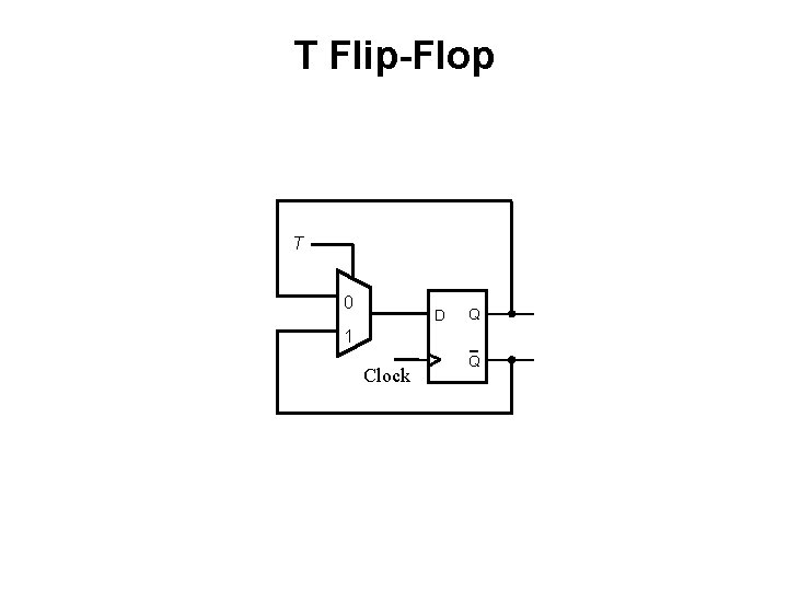
T Flip-Flop [ Figure 5. 15 a from the textbook ]
T Flip-Flop Positive-edge-triggered D Flip-Flop [ Figure 5. 15 a from the textbook ]
T Flip-Flop 2 -to-1 multiplexer [ Figure 5. 15 a from the textbook ]
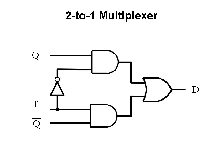
2 -to-1 Multiplexer Q D T Q
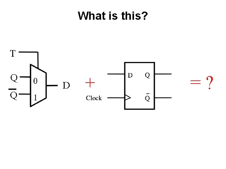
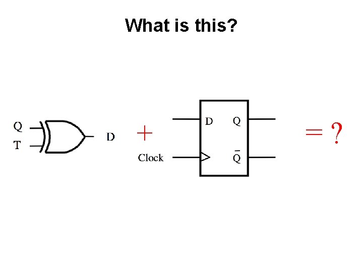
What is this? T Q Q D + =?
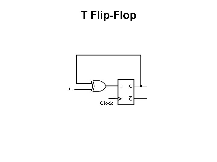
T Flip-Flop T 0 D Q 1 Clock Q
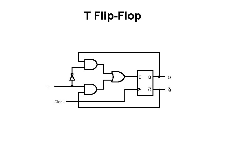
T Flip-Flop D T Clock Q Q
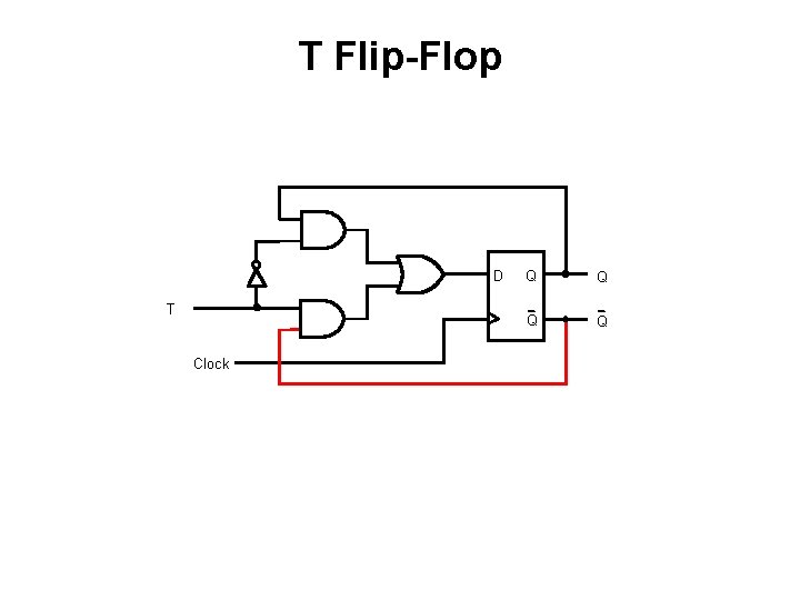
T Flip-Flop D T Clock Q Q
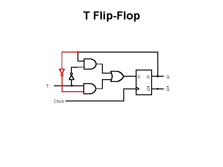
T Flip-Flop D T Clock Q Q
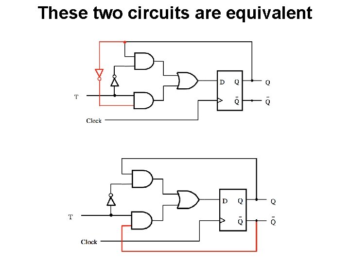
These two circuits are equivalent
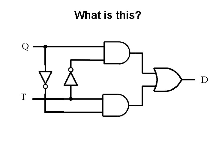
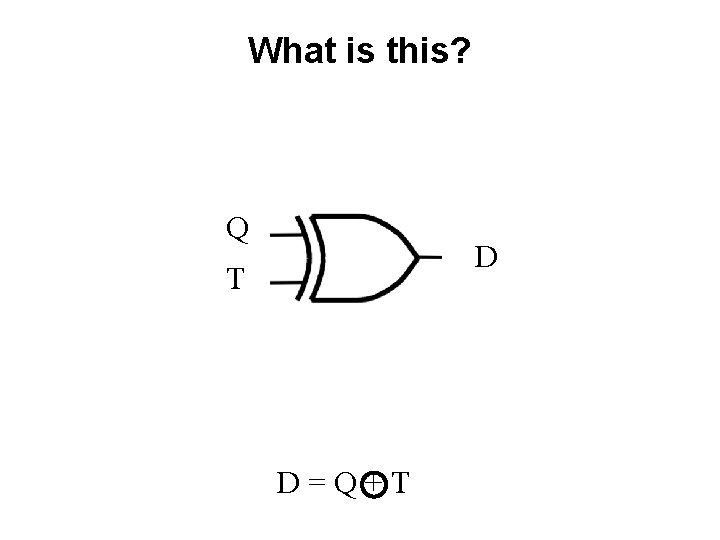
What is this? Q D T
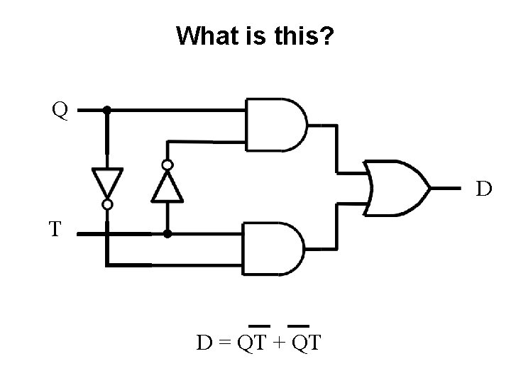
What is this? Q D T D = QT + QT
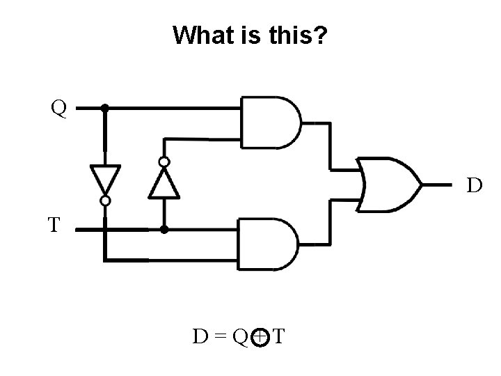
What is this? Q D T D=Q+T
What is this? Q D T D=Q+T
What is this? + =?
T Flip-Flop D T Clock Q Q
Synchronous Counter with D Flip-Flops
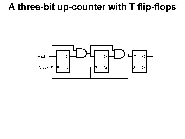
A three-bit up-counter with T flip-flops Enable Clock T Q Q
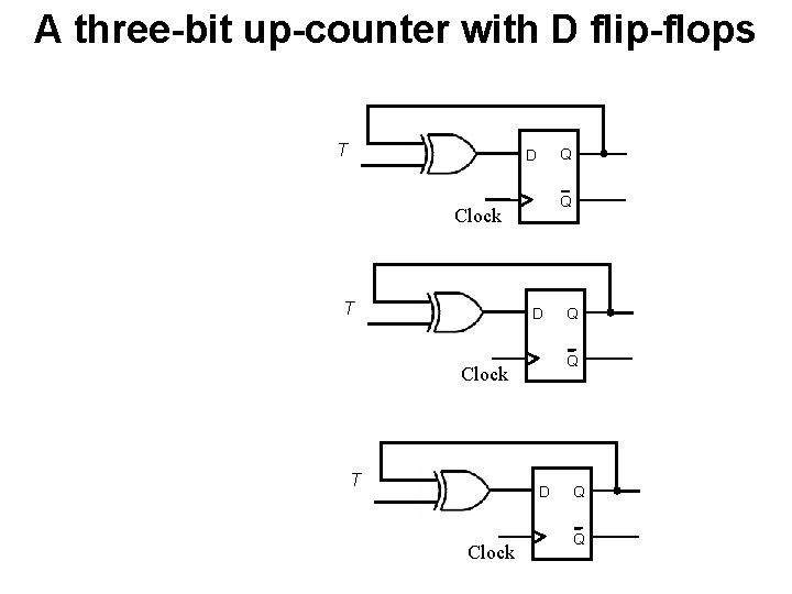
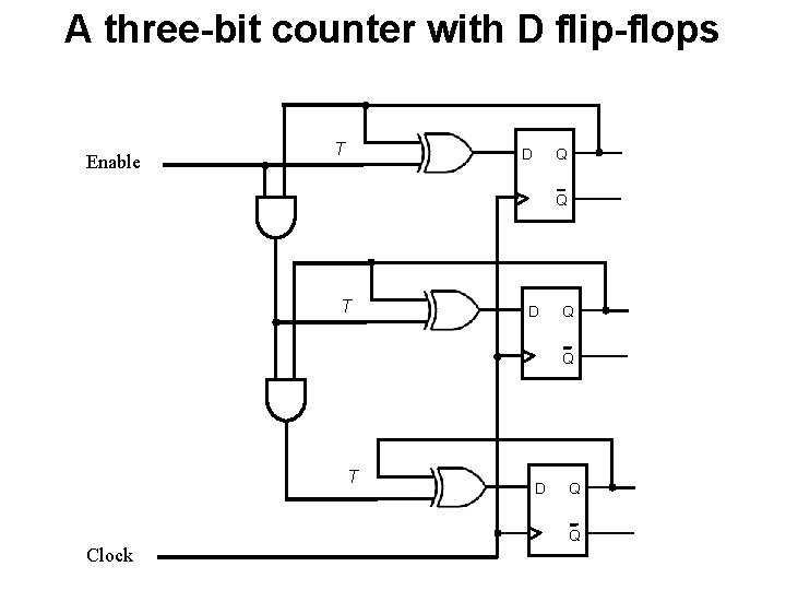
A three-bit up-counter with D flip-flops T Q D Q Clock T D Clock Q Q Q
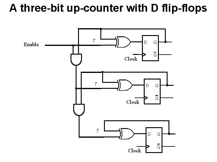
A three-bit up-counter with D flip-flops Enable T Q D Q Clock T D Clock Q Q Q
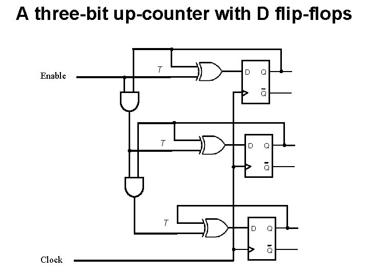
A three-bit up-counter with D flip-flops Enable T Q D Q T D Q Q Clock
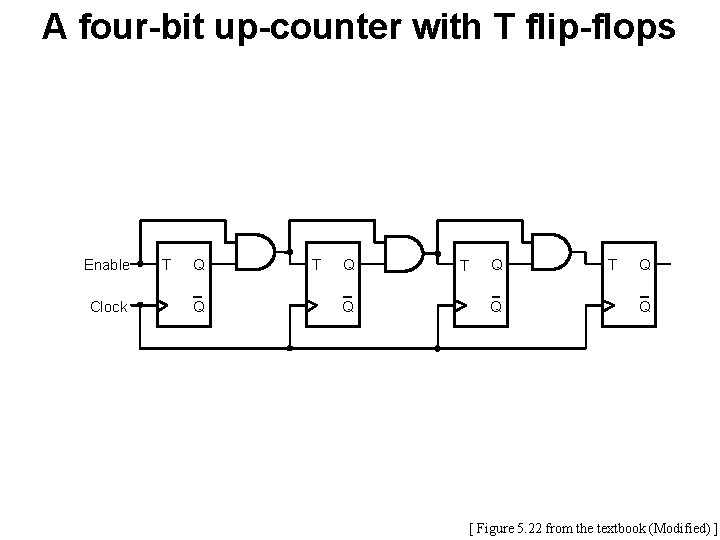
A four-bit up-counter with T flip-flops Enable Clock T Q Q [ Figure 5. 22 from the textbook (Modified) ]
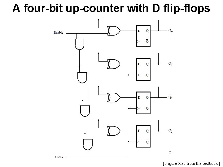
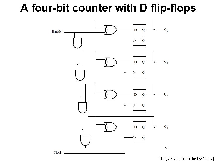
A four-bit up-counter with D flip-flops [ Figure 5. 23 from the textbook ]
End of Mini Review
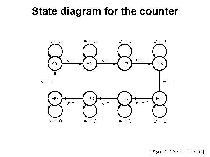
Goal • Implement a modulo-8 counter using the sequential circuit approach • In other words, the counting sequence must be 0, 1, 2, 3, 4, 5, 6, 7, 0, 1, 2, … • The count changes based on the input signal w: § If w=0, then the count remains the same § If w=1, then the count is advanced by one
State diagram for the counter w = 0 A/0 w= 1 B/1 w= 0 w= 1 C/2 w= 0 w= 1 H/7 w= 0 D/3 w= 1 G/6 w= 0 w= 1 F/5 w= 0 w= 1 E/4 w= 0 [ Figure 6. 60 from the textbook ]
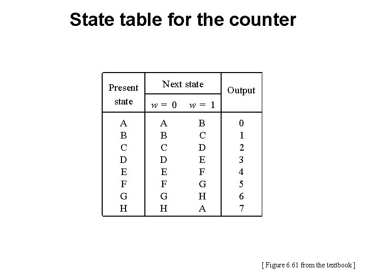
State table for the counter Next state Present state w= 0 w= 1 A B C D E F G H A Output 0 1 2 3 4 5 6 7 [ Figure 6. 61 from the textbook ]
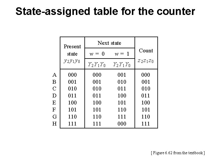
State-assigned table for the counter Present state y 2 y 1 y 0 A B C D E F G H 000 001 010 011 100 101 110 111 Next state w= 0 w= 1 Y 2 Y 1 Y 0 000 001 010 011 100 101 110 111 000 Count z 2 z 1 z 0 001 010 011 100 101 110 111 [ Figure 6. 62 from the textbook ]
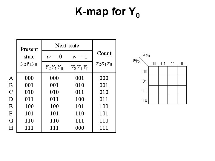
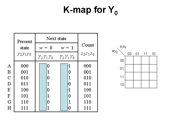
K-map for Y 0 Present state y 2 y 1 y 0 A B C D E F G H 000 001 010 011 100 101 110 111 Next state w= 0 w= 1 Y 2 Y 1 Y 0 000 001 010 011 100 101 110 111 000 Count z 2 z 1 z 0 y 1 y 0 wy 2 00 00 001 010 011 100 101 110 111 01 11 10
K-map for Y 0 Present state y 2 y 1 y 0 A B C D E F G H 000 001 010 011 100 101 110 111 Next state w= 0 w= 1 Y 2 Y 1 Y 0 000 001 010 011 100 101 110 111 000 Count z 2 z 1 z 0 y 1 y 0 wy 2 00 00 001 010 011 100 101 110 111 01 11 10
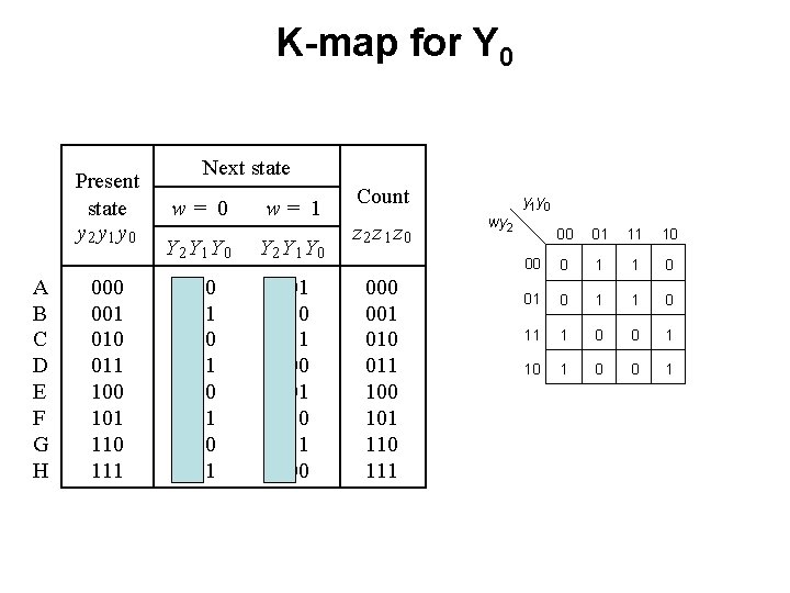
K-map for Y 0 Present state y 2 y 1 y 0 A B C D E F G H 000 001 010 011 100 101 110 111 Next state w= 0 w= 1 Y 2 Y 1 Y 0 000 001 010 011 100 101 110 111 000 Count z 2 z 1 z 0 001 010 011 100 101 110 111 y 1 y 0 wy 2 00 01 11 10 00 0 1 1 0 01 0 11 1 0 0 1 10 1 0 0 1
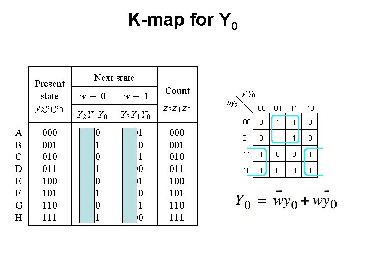
K-map for Y 0 Present state y 2 y 1 y 0 A B C D E F G H 000 001 010 011 100 101 110 111 Next state w= 0 w= 1 Y 2 Y 1 Y 0 000 001 010 011 100 101 110 111 000 Count z 2 z 1 z 0 001 010 011 100 101 110 111 y 1 y 0 wy 2 00 01 11 10 00 0 1 1 0 01 0 11 1 0 0 1 10 1 0 0 1 Y 0 = wy 0 + wy 0
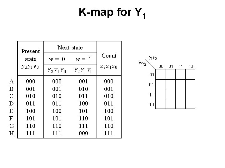
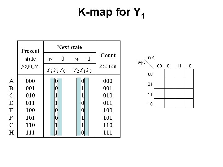
K-map for Y 1 Present state y 2 y 1 y 0 A B C D E F G H 000 001 010 011 100 101 110 111 Next state w= 0 w= 1 Y 2 Y 1 Y 0 000 001 010 011 100 101 110 111 000 Count z 2 z 1 z 0 y 1 y 0 wy 2 00 00 001 010 011 100 101 110 111 01 11 10
K-map for Y 1 Present state y 2 y 1 y 0 A B C D E F G H 000 001 010 011 100 101 110 111 Next state w= 0 w= 1 Y 2 Y 1 Y 0 000 001 010 011 100 101 110 111 000 Count z 2 z 1 z 0 y 1 y 0 wy 2 00 00 001 010 011 100 101 110 111 01 11 10
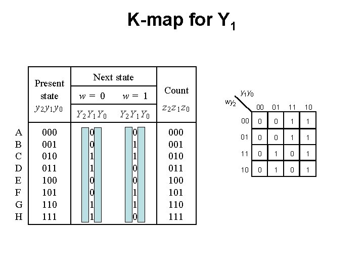
K-map for Y 1 Present state y 2 y 1 y 0 A B C D E F G H 000 001 010 011 100 101 110 111 Next state w= 0 w= 1 Y 2 Y 1 Y 0 000 001 010 011 100 101 110 111 000 Count z 2 z 1 z 0 001 010 011 100 101 110 111 y 1 y 0 wy 2 00 01 11 10 00 0 0 1 1 01 0 0 1 1 11 0 1 10 0 1
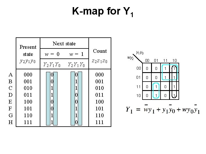
K-map for Y 1 Present state y 2 y 1 y 0 A B C D E F G H 000 001 010 011 100 101 110 111 Next state w= 0 w= 1 Y 2 Y 1 Y 0 000 001 010 011 100 101 110 111 000 Count z 2 z 1 z 0 001 010 011 100 101 110 111 y 1 y 0 wy 2 00 01 11 10 00 0 0 1 1 01 0 0 1 1 11 0 1 10 0 1 Y 1 = wy 1 + y 1 y 0 + wy 0 y 1
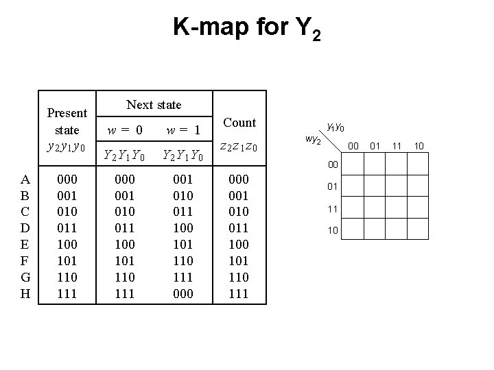
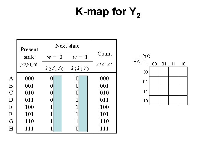
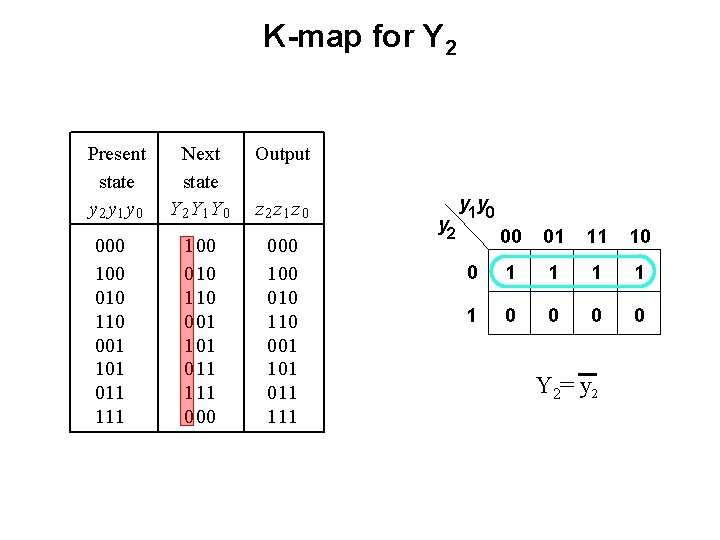
K-map for Y 2 Present state y 2 y 1 y 0 A B C D E F G H 000 001 010 011 100 101 110 111 Next state w= 0 w= 1 Y 2 Y 1 Y 0 000 001 010 011 100 101 110 111 000 Count z 2 z 1 z 0 y 1 y 0 wy 2 00 00 001 010 011 100 101 110 111 01 11 10
K-map for Y 2 Present state y 2 y 1 y 0 A B C D E F G H 000 001 010 011 100 101 110 111 Next state w= 0 w= 1 Y 2 Y 1 Y 0 000 001 010 011 100 101 110 111 000 Count z 2 z 1 z 0 y 1 y 0 wy 2 00 00 001 010 011 100 101 110 111 01 11 10
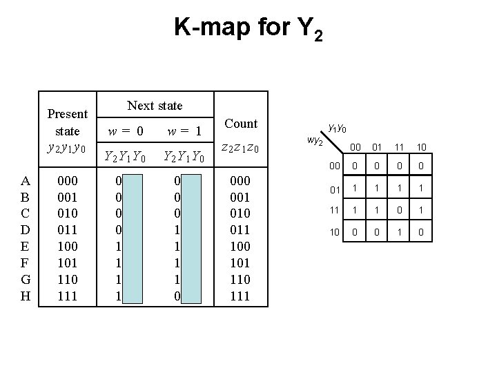
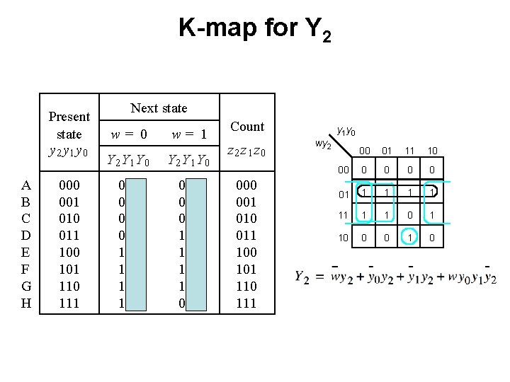
K-map for Y 2 Present state y 2 y 1 y 0 A B C D E F G H 000 001 010 011 100 101 110 111 Next state w= 0 w= 1 Y 2 Y 1 Y 0 000 001 010 011 100 101 110 111 000 Count z 2 z 1 z 0 001 010 011 100 101 110 111 y 1 y 0 wy 2 00 01 11 10 00 0 0 01 1 1 11 1 1 0 1 10 0 0 1 0
K-map for Y 2 Present state y 2 y 1 y 0 A B C D E F G H 000 001 010 011 100 101 110 111 Next state w= 0 w= 1 Y 2 Y 1 Y 0 000 001 010 011 100 101 110 111 000 Count z 2 z 1 z 0 001 010 011 100 101 110 111 y 1 y 0 wy 2 00 01 11 10 00 0 0 01 1 1 11 1 1 0 1 10 0 0 1 0
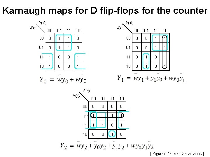
Karnaugh maps for D flip-flops for the counter y 1 y 0 wy 2 00 01 11 10 00 0 0 1 1 0 1 11 0 1 0 1 10 0 1 00 01 11 10 00 0 1 1 0 01 0 1 1 11 1 0 10 1 0 Y 1 = wy 1 + y 1 y 0 + wy 0 y 1 Y 0 = wy 0 + wy 0 y 1 y 0 wy 2 00 01 11 10 0 0 01 1 1 00 11 1 1 0 1 10 0 0 1 0 Y 2 = wy 2 + y 0 y 2 + y 1 y 2 + wy 0 y 1 y 2 [ Figure 6. 63 from the textbook ]
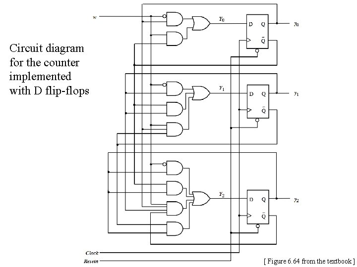
Circuit diagram for the counter implemented with D flip-flops [ Figure 6. 64 from the textbook ]
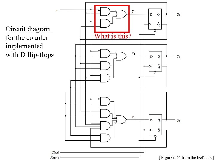
Circuit diagram for the counter implemented with D flip-flops What is this? [ Figure 6. 64 from the textbook ]
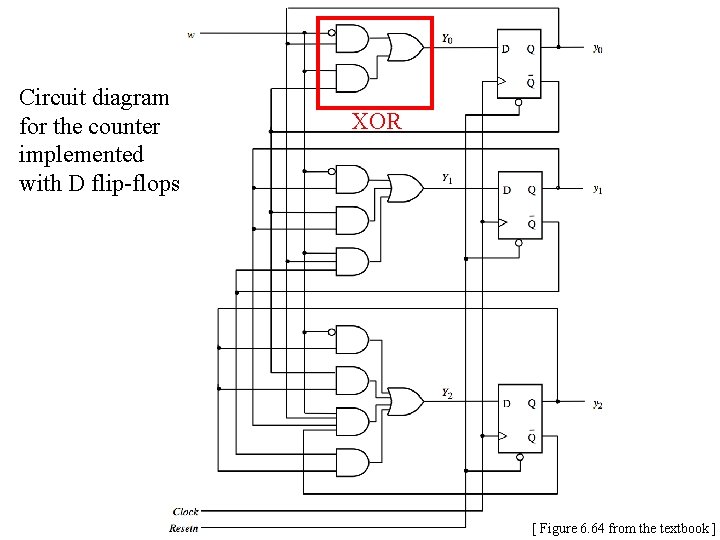
Circuit diagram for the counter implemented with D flip-flops XOR [ Figure 6. 64 from the textbook ]
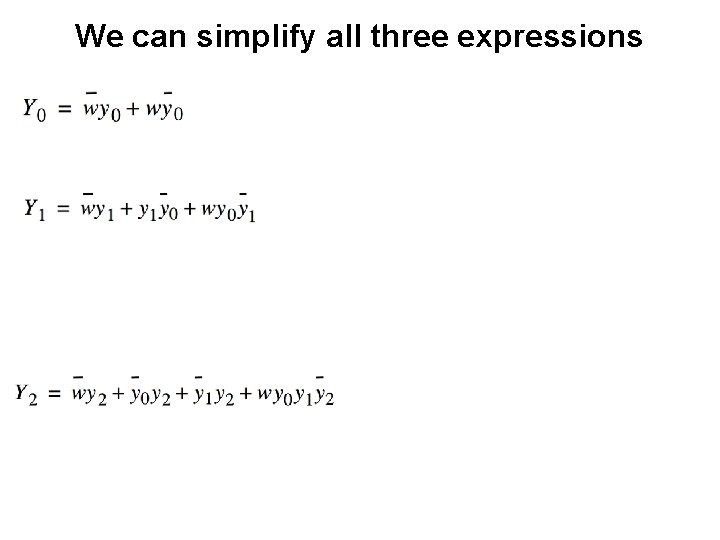
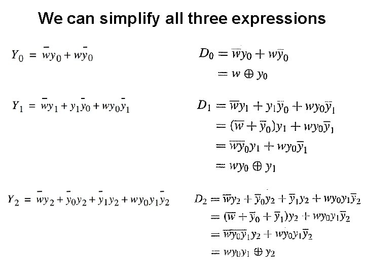
We can simplify all three expressions
We can simplify all three expressions
A three-bit counter with D flip-flops Enable T Q D Q T D Q Q Clock
A four-bit counter with D flip-flops [ Figure 5. 23 from the textbook ]
Summary • The up-counters that we studied in Chapter 5 can now be derived using the sequential circuit approach • We get the same circuit diagrams as before
Example 2: Implement a modulo-8 counter using JK Flip-Flops
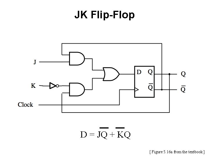
JK Flip-Flop D = JQ + KQ [ Figure 5. 16 a from the textbook ]
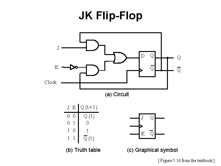
JK Flip-Flop J D K Q Q Clock (a) Circuit J K Q ( t + 1) 0 0 1 1 0 1 Q (t) 0 1 Q (t ) (b) Truth table J Q K Q (c) Graphical symbol [ Figure 5. 16 from the textbook ]
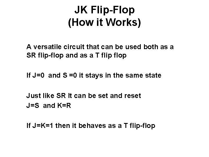
JK Flip-Flop (How it Works) A versatile circuit that can be used both as a SR flip-flop and as a T flip flop If J=0 and S =0 it stays in the same state Just like SR It can be set and reset J=S and K=R If J=K=1 then it behaves as a T flip-flop
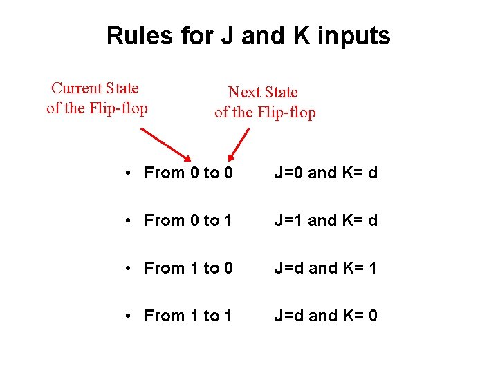
Rules for J and K inputs Current State of the Flip-flop Next State of the Flip-flop • From 0 to 0 J=0 and K= d • From 0 to 1 J=1 and K= d • From 1 to 0 J=d and K= 1 • From 1 to 1 J=d and K= 0
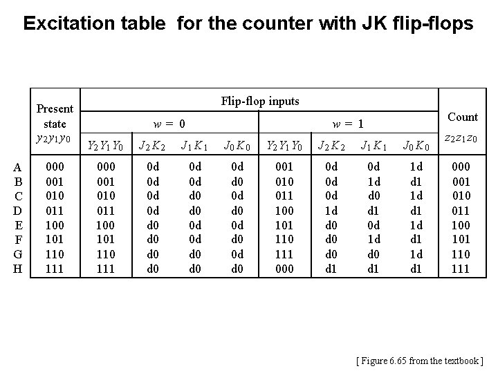
Excitation table for the counter with JK flip-flops Present state y 2 y 1 y 0 A B C D E F G H 000 001 010 011 100 101 110 111 Flip-flop inputs w= 0 Count w= 1 Y 2 Y 1 Y 0 J 2 K 2 J 1 K 1 J 0 K 0 000 001 010 011 100 101 110 111 0 d 0 d d 0 d 0 0 d d 0 001 010 011 100 101 110 111 000 0 d 0 d 0 d 1 d d 0 d 0 d 1 0 d 1 d d 0 d 1 1 d d 1 z 2 z 1 z 0 001 010 011 100 101 110 111 [ Figure 6. 65 from the textbook ]
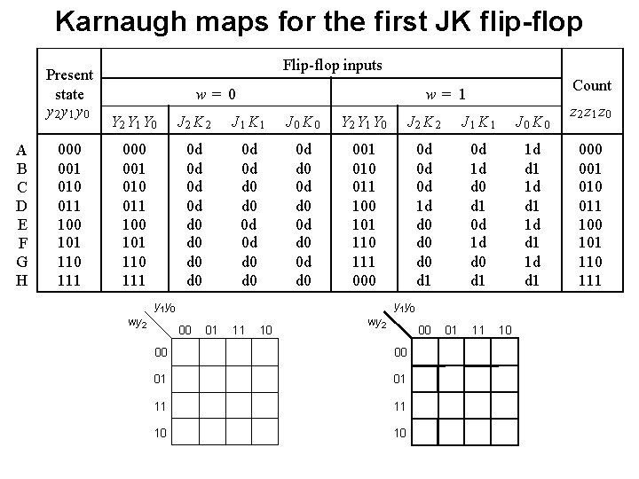
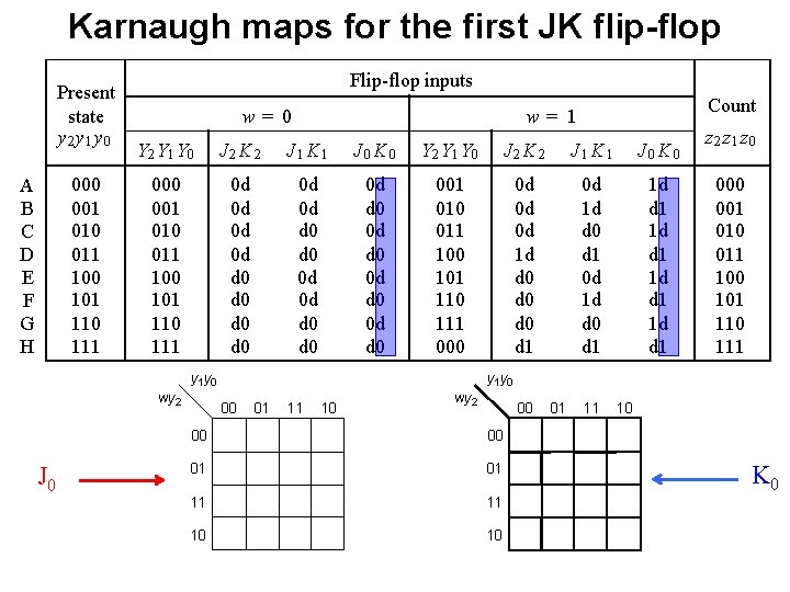
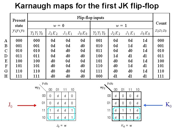
Karnaugh maps for the first JK flip-flop Present state y 2 y 1 y 0 A B C D E F G H 000 001 010 011 100 101 110 111 Flip-flop inputs w= 0 Count w= 1 Y 2 Y 1 Y 0 J 2 K 2 J 1 K 1 J 0 K 0 000 001 010 011 100 101 110 111 0 d 0 d d 0 d 0 0 d d 0 001 010 011 100 101 110 111 000 0 d 0 d 0 d 1 d d 0 d 0 d 1 0 d 1 d d 0 d 1 1 d d 1 y 0 wy 2 y 1 y 0 00 01 11 10 wy 2 00 00 00 01 01 11 11 10 10 01 11 10 z 2 z 1 z 0 001 010 011 100 101 110 111
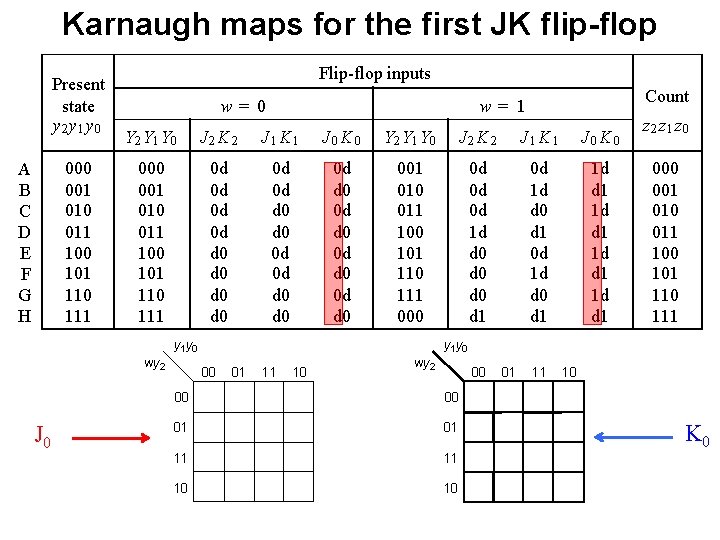
Karnaugh maps for the first JK flip-flop Present state y 2 y 1 y 0 001 010 011 100 101 110 111 A B C D E F G H Flip-flop inputs w= 0 Y 2 Y 1 Y 0 J 2 K 2 J 1 K 1 J 0 K 0 001 010 011 100 101 110 111 0 d 0 d d 0 d 0 0 d d 0 001 010 011 100 101 110 111 000 0 d 0 d 0 d 1 d d 0 d 0 d 1 0 d 1 d d 0 d 1 1 d d 1 y 0 wy 2 J 0 Count w= 1 z 2 z 1 z 0 001 010 011 100 101 110 111 y 0 00 01 11 10 wy 2 00 00 00 01 01 11 11 10 10 01 11 10 K 0
Karnaugh maps for the first JK flip-flop Present state y 2 y 1 y 0 001 010 011 100 101 110 111 A B C D E F G H Flip-flop inputs w= 0 Y 2 Y 1 Y 0 J 2 K 2 J 1 K 1 J 0 K 0 001 010 011 100 101 110 111 0 d 0 d d 0 d 0 0 d d 0 001 010 011 100 101 110 111 000 0 d 0 d 0 d 1 d d 0 d 0 d 1 0 d 1 d d 0 d 1 1 d d 1 y 0 wy 2 J 0 Count w= 1 z 2 z 1 z 0 001 010 011 100 101 110 111 y 0 00 01 11 10 wy 2 00 00 00 01 01 11 11 10 10 01 11 10 K 0
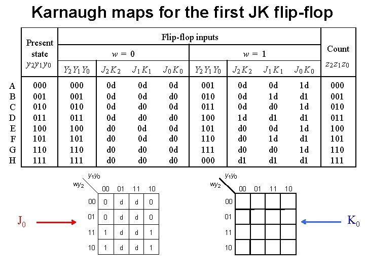
Karnaugh maps for the first JK flip-flop Present state y 2 y 1 y 0 001 010 011 100 101 110 111 A B C D E F G H Flip-flop inputs w= 0 Y 2 Y 1 Y 0 J 2 K 2 J 1 K 1 J 0 K 0 001 010 011 100 101 110 111 0 d 0 d d 0 d 0 0 d d 0 001 010 011 100 101 110 111 000 0 d 0 d 0 d 1 d d 0 d 0 d 1 0 d 1 d d 0 d 1 1 d d 1 y 0 wy 2 J 0 Count w= 1 z 2 z 1 z 0 001 010 011 100 101 110 111 y 0 wy 2 00 01 11 10 00 00 0 d d 0 00 01 0 d d 0 01 11 1 d d 1 11 10 1 d d 1 10 01 11 10 K 0
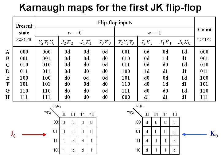
Karnaugh maps for the first JK flip-flop Present state y 2 y 1 y 0 001 010 011 100 101 110 111 A B C D E F G H Flip-flop inputs w= 0 Y 2 Y 1 Y 0 J 2 K 2 J 1 K 1 J 0 K 0 001 010 011 100 101 110 111 0 d 0 d d 0 d 0 0 d d 0 001 010 011 100 101 110 111 000 0 d 0 d 0 d 1 d d 0 d 0 d 1 0 d 1 d d 0 d 1 1 d d 1 y 0 wy 2 J 0 Count w= 1 z 2 z 1 z 0 001 010 011 100 101 110 111 y 0 00 01 11 10 00 0 d d 0 01 0 d d 11 1 d 10 1 d wy 2 00 01 11 10 00 d 0 01 d 0 0 d d 1 11 d 1 1 d d 1 10 d 1 1 d K 0
Karnaugh maps for the first JK flip-flop Present state y 2 y 1 y 0 001 010 011 100 101 110 111 A B C D E F G H Flip-flop inputs w= 0 Y 2 Y 1 Y 0 J 2 K 2 J 1 K 1 J 0 K 0 001 010 011 100 101 110 111 0 d 0 d d 0 d 0 0 d d 0 001 010 011 100 101 110 111 000 0 d 0 d 0 d 1 d d 0 d 0 d 1 0 d 1 d d 0 d 1 1 d d 1 y 0 wy 2 J 0 Count w= 1 z 2 z 1 z 0 001 010 011 100 101 110 111 y 0 00 01 11 10 00 0 d d 0 01 0 d d 11 1 d 10 1 d wy 2 00 01 11 10 00 d 0 01 d 0 0 d d 1 11 d 1 1 d d 1 10 d 1 1 d K 0
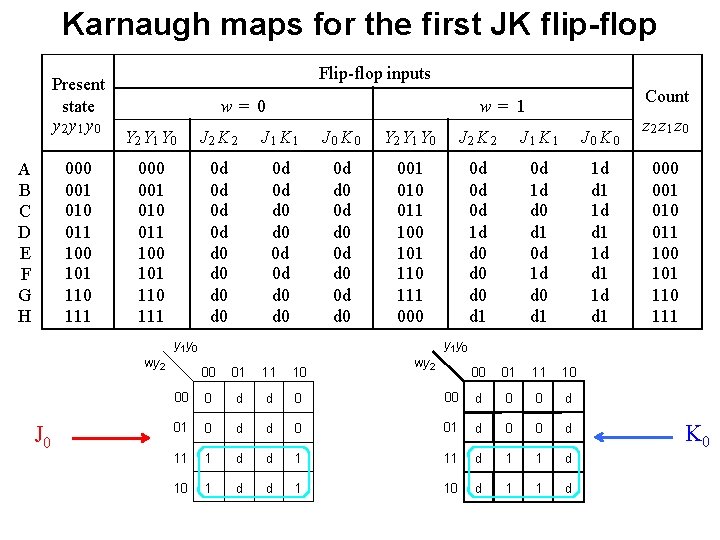
Karnaugh maps for the first JK flip-flop Present state y 2 y 1 y 0 001 010 011 100 101 110 111 A B C D E F G H Flip-flop inputs w= 0 Y 2 Y 1 Y 0 J 2 K 2 J 1 K 1 J 0 K 0 001 010 011 100 101 110 111 0 d 0 d d 0 d 0 0 d d 0 001 010 011 100 101 110 111 000 0 d 0 d 0 d 1 d d 0 d 0 d 1 0 d 1 d d 0 d 1 1 d d 1 y 0 wy 2 J 0 Count w= 1 z 2 z 1 z 0 001 010 011 100 101 110 111 y 0 00 01 11 10 00 0 d d 0 01 0 d d 11 1 d 10 1 d wy 2 00 01 11 10 00 d 0 01 d 0 0 d d 1 11 d 1 1 d d 1 10 d 1 1 d J 0 = w K 0
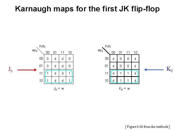
Karnaugh maps for the first JK flip-flop y 1 y 0 wy 2 J 0 y 1 y 0 00 01 11 10 00 0 d d 0 01 0 d d 11 1 d 10 1 d wy 2 00 01 11 10 00 d 0 01 d 0 0 d d 1 11 d 1 1 d d 1 10 d 1 1 d J 0 = w K 0 = w [ Figure 6. 66 from the textbook ]
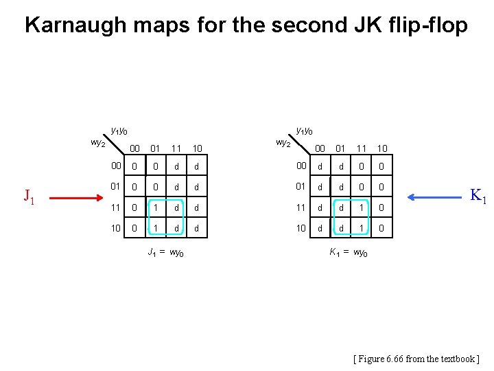
Karnaugh maps for the second JK flip-flop y 1 y 0 wy 2 J 1 y 0 00 01 11 10 00 0 0 d d 01 0 0 d 11 0 1 10 0 1 wy 2 00 01 11 10 00 d d 0 0 d 01 d d 0 0 d d 11 d d 1 0 J 1 = wy 0 K 1 = wy 0 [ Figure 6. 66 from the textbook ]
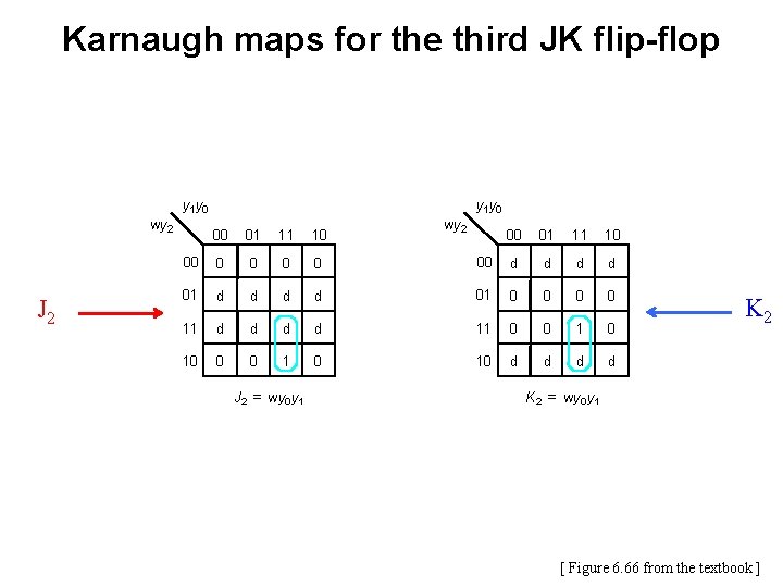
Karnaugh maps for the third JK flip-flop y 1 y 0 wy 2 J 2 y 1 y 0 00 01 11 10 00 0 0 01 d d d 11 d d 10 0 0 wy 2 00 01 11 10 00 d d d 01 0 0 d d 11 0 0 1 0 10 d d J 2 = wy 0 y 1 K 2 = wy 0 y 1 [ Figure 6. 66 from the textbook ]
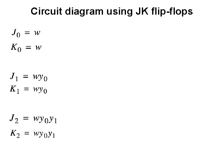
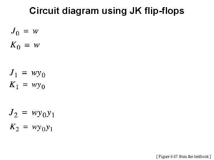
Circuit diagram using JK flip-flops
Circuit diagram using JK flip-flops [ Figure 6. 67 from the textbook ]
Factored-form implementation of the counter [ Figure 6. 68 from the textbook ]
Another Example (A Different “Counter”)
Goal • Implement a 3 -bit counter using the sequential circuit approach that counts the pulses on the input line w. • The counter must count in the following sequence: 0, 4, 2, 6, 1, 5, 3, 7, 0, 4, 2, … • The count must be represented directly by the flipflop values. No extra gates are allowed. • In other words, count = Q 2 Q 1 Q 0 • The count changes based on the input signal w: § If w=0, then the count remains the same § If w=1, then the count is advanced by one
Goal • Implement a 3 -bit counter using the sequential circuit approach that counts the pulses on the input line w. • The counter must count in the following sequence: 0, 4, 2, 6, 1, 5, 3, 7, 0, 4, 2, … • The count must be represented directly by the flipflop values. No extra gates are allowed. • In other words, count = Q 2 Q 1 Q 0 • The count changes based on the input signal w: § If w=0, then the count remains the same § If w=1, then the count is advanced by one Clock = w
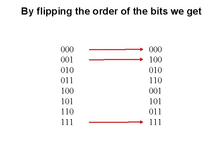
By flipping the order of the bits we get 000 001 010 011 100 101 110 111 000 100 010 110 001 101 011 111
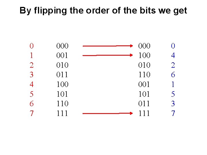
By flipping the order of the bits we get 0 1 2 3 4 5 6 7 000 001 010 011 100 101 110 111 000 100 010 110 001 101 011 111 0 4 2 6 1 5 3 7
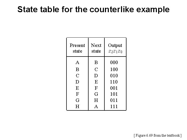
State table for the counterlike example Present state Next state Output z 2 z 1 z 0 A B C D E F G H A 000 100 010 110 001 101 011 111 [ Figure 6. 69 from the textbook ]
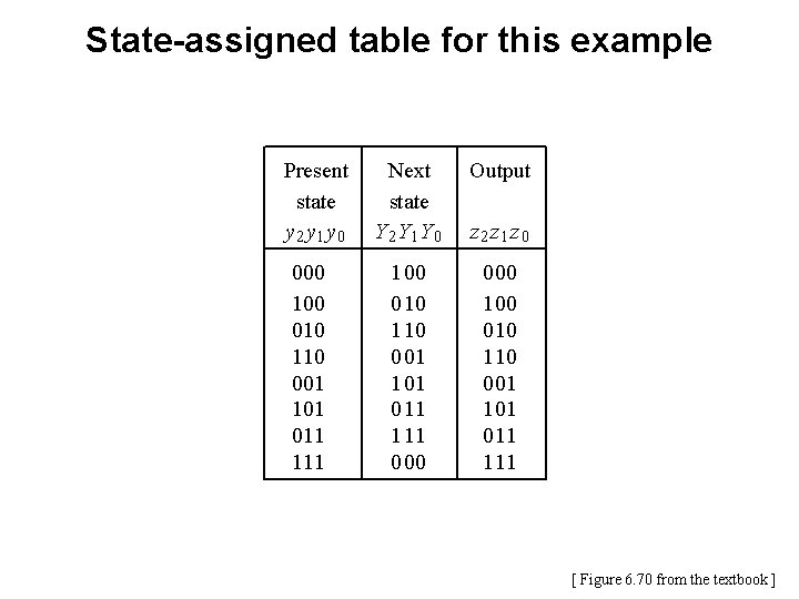
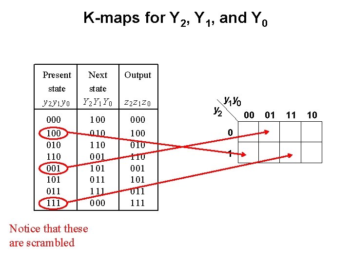
State-assigned table for this example Present state y 2 y 1 y 0 000 100 010 110 001 101 011 111 Next state Y 2 Y 1 Y 0 Output 1 00 0 10 1 10 0 01 1 01 0 11 1 11 0 00 1 00 0 10 1 10 0 01 1 01 0 11 1 11 z 2 z 1 z 0 [ Figure 6. 70 from the textbook ]
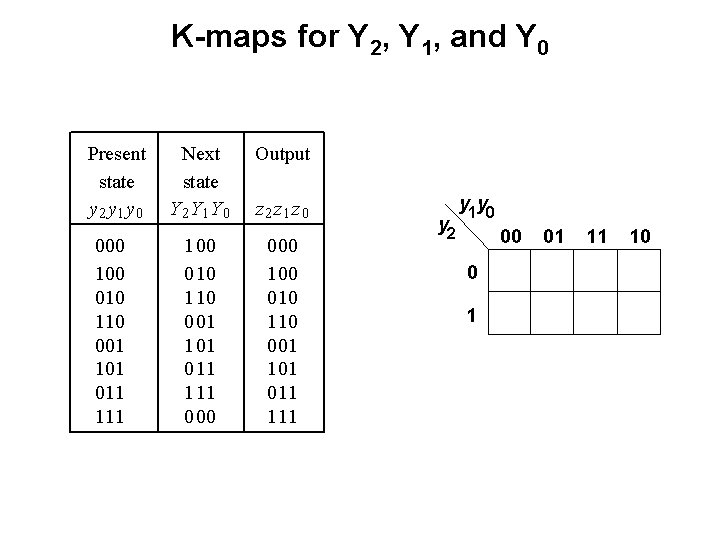
K-maps for Y 2, Y 1, and Y 0 Present state y 2 y 1 y 0 000 100 010 110 001 101 011 111 Next state Y 2 Y 1 Y 0 Output 1 00 0 10 1 10 0 01 1 01 0 11 1 11 0 00 1 00 0 10 1 10 0 01 1 01 0 11 1 11 z 2 z 1 z 0 y 2 y 1 y 0 00 0 1 01 11 10
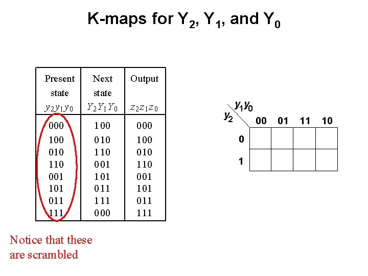
K-maps for Y 2, Y 1, and Y 0 Present state y 2 y 1 y 0 Next state Y 2 Y 1 Y 0 Output 1 00 0 10 1 10 0 01 1 01 0 11 1 11 0 00 1 00 0 10 1 10 0 01 1 01 0 11 1 11 000 100 010 110 001 101 011 111 Notice that these are scrambled z 2 z 1 z 0 y 2 y 1 y 0 00 0 1 01 11 10
K-maps for Y 2, Y 1, and Y 0 Present state y 2 y 1 y 0 Next state Y 2 Y 1 Y 0 Output 1 00 0 10 1 10 0 01 1 01 0 11 1 11 0 00 1 00 0 10 1 10 0 01 1 01 0 11 1 11 000 100 010 110 001 101 011 111 Notice that these are scrambled z 2 z 1 z 0 y 2 y 1 y 0 00 0 1 01 11 10
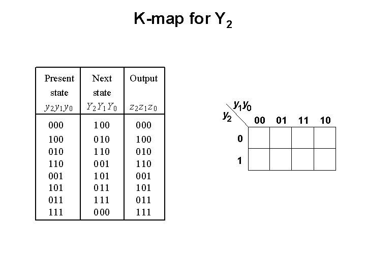
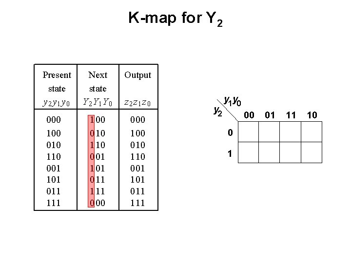
K-map for Y 2 Present state y 2 y 1 y 0 000 100 010 110 001 101 011 111 Next state Y 2 Y 1 Y 0 Output 1 00 0 10 1 10 0 01 1 01 0 11 1 11 0 00 1 00 0 10 1 10 0 01 1 01 0 11 1 11 z 2 z 1 z 0 y 2 y 1 y 0 00 0 1 01 11 10
K-map for Y 2 Present state y 2 y 1 y 0 000 100 010 110 001 101 011 111 Next state Y 2 Y 1 Y 0 Output 1 00 0 10 1 10 0 01 1 01 0 11 1 11 0 00 1 00 0 10 1 10 0 01 1 01 0 11 1 11 z 2 z 1 z 0 y 2 y 1 y 0 00 0 1 01 11 10
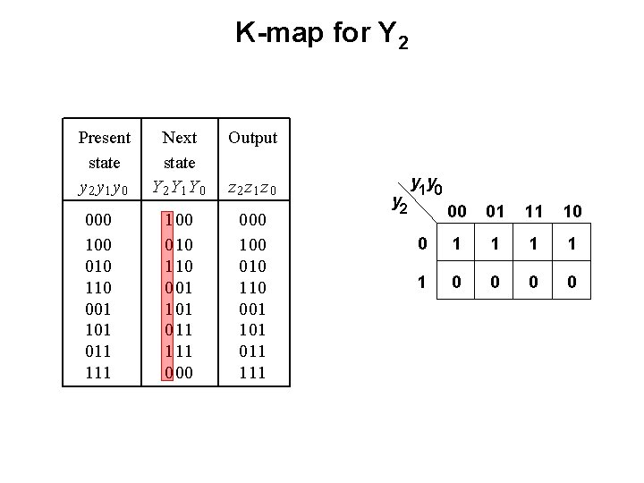
K-map for Y 2 Present state y 2 y 1 y 0 000 100 010 110 001 101 011 111 Next state Y 2 Y 1 Y 0 Output 1 00 0 10 1 10 0 01 1 01 0 11 1 11 0 00 1 00 0 10 1 10 0 01 1 01 0 11 1 11 z 2 z 1 z 0 y 2 y 1 y 0 00 01 11 10 0 1 1 1 0 0
K-map for Y 2 Present state y 2 y 1 y 0 000 100 010 110 001 101 011 111 Next state Y 2 Y 1 Y 0 Output 1 00 0 10 1 10 0 01 1 01 0 11 1 11 0 00 1 00 0 10 1 10 0 01 1 01 0 11 1 11 z 2 z 1 z 0 y 2 y 1 y 0 00 01 11 10 0 1 1 1 0 0 Y 2= y 2
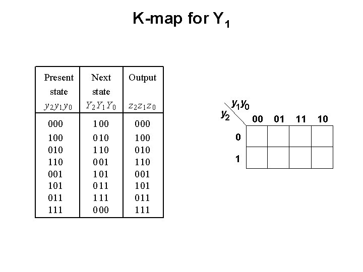
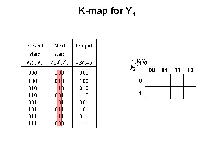
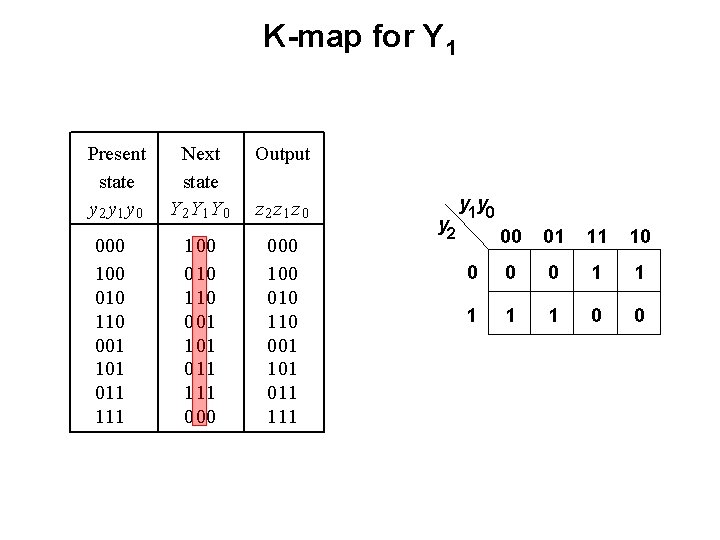
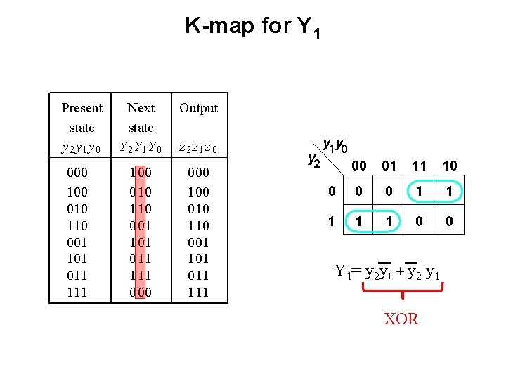
K-map for Y 1 Present state y 2 y 1 y 0 000 100 010 110 001 101 011 111 Next state Y 2 Y 1 Y 0 Output 1 00 0 10 1 10 0 01 1 01 0 11 1 11 0 00 1 00 0 10 1 10 0 01 1 01 0 11 1 11 z 2 z 1 z 0 y 2 y 1 y 0 00 0 1 01 11 10
K-map for Y 1 Present state y 2 y 1 y 0 000 100 010 110 001 101 011 111 Next state Y 2 Y 1 Y 0 Output 1 00 0 10 1 10 0 01 1 01 0 11 1 11 0 00 1 00 0 10 1 10 0 01 1 01 0 11 1 11 z 2 z 1 z 0 y 2 y 1 y 0 00 0 1 01 11 10
K-map for Y 1 Present state y 2 y 1 y 0 000 100 010 110 001 101 011 111 Next state Y 2 Y 1 Y 0 Output 1 00 0 10 1 10 0 01 1 01 0 11 1 11 0 00 1 00 0 10 1 10 0 01 1 01 0 11 1 11 z 2 z 1 z 0 y 2 y 1 y 0 00 01 11 10 0 1 1 1 0 0
K-map for Y 1 Present state y 2 y 1 y 0 000 100 010 110 001 101 011 111 Next state Y 2 Y 1 Y 0 Output 1 00 0 10 1 10 0 01 1 01 0 11 1 11 0 00 1 00 0 10 1 10 0 01 1 01 0 11 1 11 z 2 z 1 z 0 y 2 y 1 y 0 00 01 11 10 0 1 1 1 0 0 Y 1= y 2 y 1 + y 2 y 1 XOR
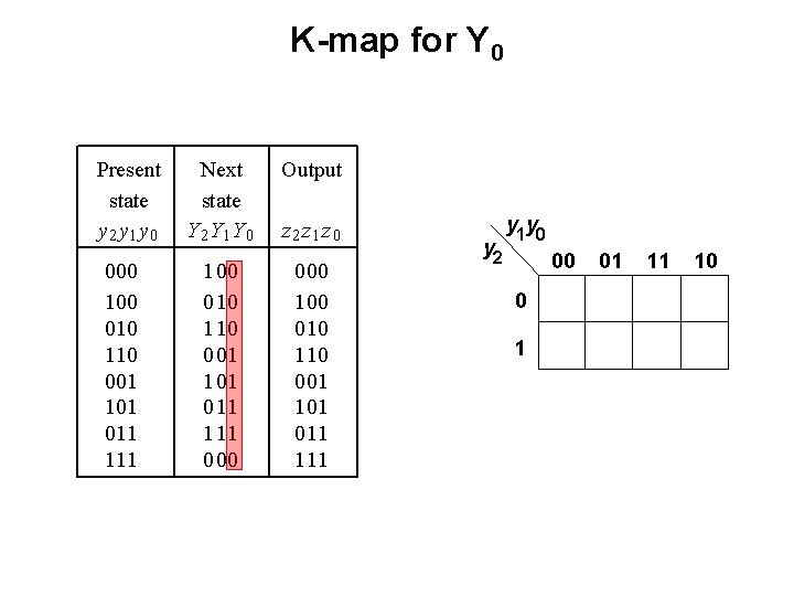
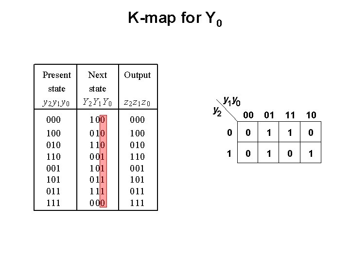
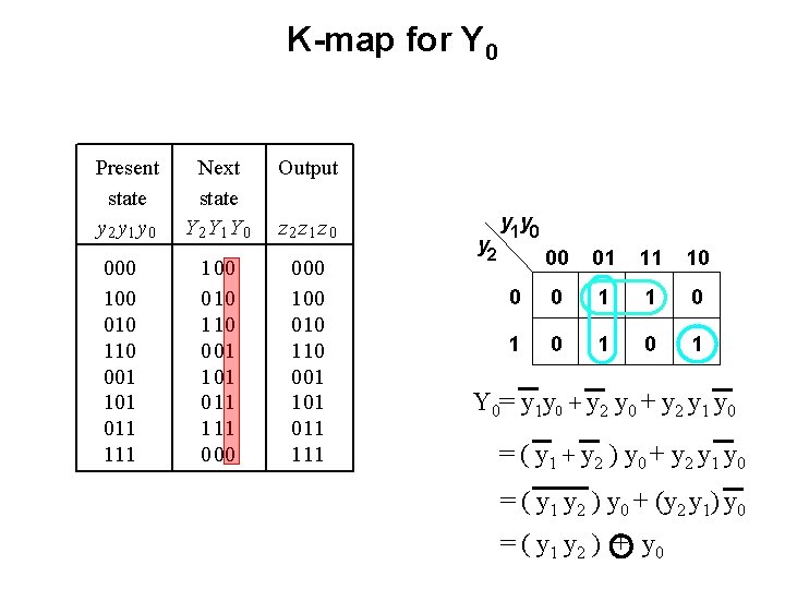
K-map for Y 0 Present state y 2 y 1 y 0 000 100 010 110 001 101 011 111 Next state Y 2 Y 1 Y 0 Output 1 00 0 10 1 10 0 01 1 01 0 11 1 11 0 00 1 00 0 10 1 10 0 01 1 01 0 11 1 11 z 2 z 1 z 0 y 2 y 1 y 0 00 0 1 01 11 10
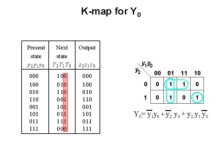
K-map for Y 0 Present state y 2 y 1 y 0 000 100 010 110 001 101 011 111 Next state Y 2 Y 1 Y 0 Output 1 00 0 10 1 10 0 01 1 01 0 11 1 11 0 00 1 00 0 10 1 10 0 01 1 01 0 11 1 11 z 2 z 1 z 0 y 2 y 1 y 0 00 01 11 10 0 0 1 1 0 1 0 1
K-map for Y 0 Present state y 2 y 1 y 0 000 100 010 110 001 101 011 111 Next state Y 2 Y 1 Y 0 Output 1 00 0 10 1 10 0 01 1 01 0 11 1 11 0 00 1 00 0 10 1 10 0 01 1 01 0 11 1 11 z 2 z 1 z 0 y 2 y 1 y 0 00 01 11 10 0 0 1 1 0 1 0 1 Y 0= y 1 y 0 + y 2 y 1 y 0
K-map for Y 0 Present state y 2 y 1 y 0 000 100 010 110 001 101 011 111 Next state Y 2 Y 1 Y 0 Output 1 00 0 10 1 10 0 01 1 01 0 11 1 11 0 00 1 00 0 10 1 10 0 01 1 01 0 11 1 11 z 2 z 1 z 0 y 2 y 1 y 0 00 01 11 10 0 0 1 1 0 1 0 1 Y 0= y 1 y 0 + y 2 y 1 y 0 = ( y 1 + y 2 ) y 0 + y 2 y 1 y 0 = ( y 1 y 2 ) y 0 + (y 2 y 1) y 0 = ( y 1 y 2 ) + y 0
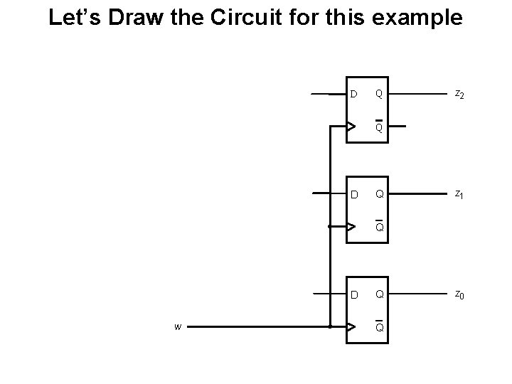
Let’s Draw the Circuit for this example D Q z 2 Q D Q z 1 Q D w Q Q z 0
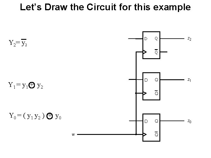
Let’s Draw the Circuit for this example D Y 2= y 2 Q z 2 Q D Y 1 = y 1 + y 2 Q z 1 Q Y 0 = ( y 1 y 2 ) + y 0 D w Q Q z 0
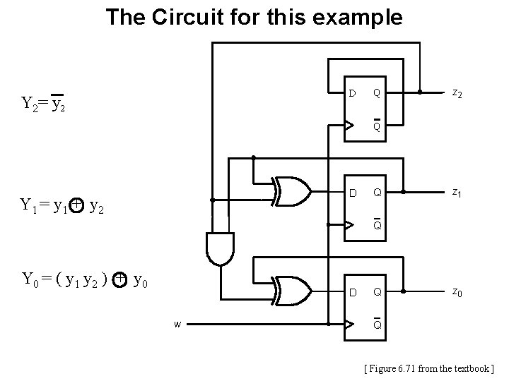
The Circuit for this example D Y 2= y 2 Q z 2 Q D Y 1 = y 1 + y 2 Q z 1 Q Y 0 = ( y 1 y 2 ) + y 0 D w Q z 0 Q [ Figure 6. 71 from the textbook ]
Questions?
THE END