Cpr E 281 Digital Logic Instructor Alexander Stoytchev


")
")
")
")
")
")


![Minterms and Maxterms (with three variables) [ Figure 2. 22 from the textbook ]](https://slidetodoc.com/presentation_image/3d21a36a6fec3ff1daba227e2e98d1b9/image-19.jpg "Minterms and Maxterms (with three variables) [ Figure 2. 22 from the textbook ]")
 The function is 1 for these rows")
 The function is 1 for these rows The")

 = Π M(1, 3) =")
 = ( x 1")


 x 22")

 = Σ")
 = Σ")
![The SOP Expression [ Figure 2. 67 a from the textbook ]](https://slidetodoc.com/presentation_image/3d21a36a6fec3ff1daba227e2e98d1b9/image-47.jpg "The SOP Expression [ Figure 2. 67 a from the textbook ]")
 =")
![The POS Expression [ Figure 2. 67 b from the textbook ]](https://slidetodoc.com/presentation_image/3d21a36a6fec3ff1daba227e2e98d1b9/image-49.jpg "The POS Expression [ Figure 2. 67 b from the textbook ]")


![The SOP Expression [ Figure 2. 68 a from the textbook ]](https://slidetodoc.com/presentation_image/3d21a36a6fec3ff1daba227e2e98d1b9/image-54.jpg "The SOP Expression [ Figure 2. 68 a from the textbook ]")

![The POS Expression [ Figure 2. 68 b from the textbook ]](https://slidetodoc.com/presentation_image/3d21a36a6fec3ff1daba227e2e98d1b9/image-56.jpg "The POS Expression [ Figure 2. 68 b from the textbook ]")


![Construct the K-Map for this expression [ Figure 2. 69 from the textbook ]](https://slidetodoc.com/presentation_image/3d21a36a6fec3ff1daba227e2e98d1b9/image-60.jpg "Construct the K-Map for this expression [ Figure 2. 69 from the textbook ]")


![Logic Circuit [ Figure 2. 70 from the textbook ]](https://slidetodoc.com/presentation_image/3d21a36a6fec3ff1daba227e2e98d1b9/image-63.jpg "Logic Circuit [ Figure 2. 70 from the textbook ]")
 Circuit")
![Logic Circuit vs Verilog Code [ Figure 2. 70 from the textbook ] [](https://slidetodoc.com/presentation_image/3d21a36a6fec3ff1daba227e2e98d1b9/image-65.jpg "Logic Circuit vs Verilog Code [ Figure 2. 70 from the textbook ] [")

![The Logic Circuit for this Example [ Figure 2. 72 from the textbook ]](https://slidetodoc.com/presentation_image/3d21a36a6fec3ff1daba227e2e98d1b9/image-67.jpg "The Logic Circuit for this Example [ Figure 2. 72 from the textbook ]")
 Circuit")

![Logic Circuit vs Verilog Code [ Figure 2. 73 from the textbook ]](https://slidetodoc.com/presentation_image/3d21a36a6fec3ff1daba227e2e98d1b9/image-70.jpg "Logic Circuit vs Verilog Code [ Figure 2. 73 from the textbook ]")

 x 1 x 2 xn Input buffers and inverters x")


 x 1 x 2 x 3 P 1 P 2")
 x 1 x 2 x 3 P 1 P 2")


- Slides: 78
Cpr. E 281: Digital Logic Instructor: Alexander Stoytchev http: //www. ece. iastate. edu/~alexs/classes/
Examples of Solved Problems Cpr. E 281: Digital Logic Iowa State University, Ames, IA Copyright © Alexander Stoytchev
Administrative Stuff • HW 5 is out • It is due on Monday Oct 2 @ 4 pm. • Please write clearly on the first page (in block capital letters) the following three things: § Your First and Last Name § Your Student ID Number § Your Lab Section Letter • Also, staple all of your pages together
Administrative Stuff • No homework is due next week.
Administrative Stuff • Midterm Exam #1 • When: Friday Sep 22. • Where: This classroom • What: Chapter 1 and Chapter 2 plus number systems • The exam will be open book and open notes (you can bring up to 3 pages of handwritten notes).
Topics for the Midterm Exam • • • Binary Numbers Octal Numbers Hexadecimal Numbers Conversion between the different number systems Truth Tables Boolean Algebra Logic Gates Circuit Synthesis with AND, OR, NOT Circuit Synthesis with NAND, NOR Converting an AND/OR/NOT circuit to NAND circuit Converting an AND/OR/NOT circuit to NOR circuit SOP and POS expressions
Topics for the Midterm Exam • Mapping a Circuit to Verilog code • Mapping Verilog code to a circuit • Multiplexers • Venn Diagrams • K-maps for 2, 3, and 4 variables • Minimization of Boolean expressions using theorems • Minimization of Boolean expressions with K-maps • Incompletely specified functions (with don’t cares) • Functions with multiple outputs
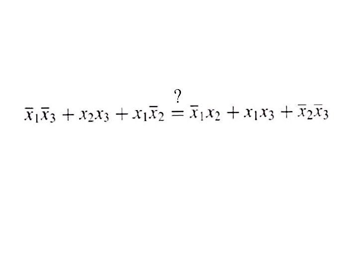
Example 1 Determine if the following equation is valid
? LHS RHS
Left-Hand Side (LHS)
Left-Hand Side (LHS)
Left-Hand Side (LHS)
Right-Hand Side (RHS)
Right-Hand Side (RHS)
Right-Hand Side (RHS)
? RHS LHS They are equal.
Example 2 Design the minimum-cost product-of-sums expression for the function f(x 1, x 2, x 3) = Σ m(0, 2, 4, 5, 6, 7)
Minterms and Maxterms (with three variables) [ Figure 2. 22 from the textbook ]
Minterms and Maxterms (with three variables) The function is 1 for these rows
Minterms and Maxterms (with three variables) The function is 1 for these rows The function is 0 for these rows
Two different ways to specify the same function f of three variables f(x 1, x 2, x 3) = Σ m(0, 2, 4, 5, 6, 7) f(x 1, x 2, x 3) = Π M(1, 3)
The POS Expression f(x 1, x 2, x 3) = Π M(1, 3) = M 1 M 3 = ( x 1 + x 2 + x 3)
The Minimum POS Expression f(x 1, x 2, x 3) = ( x 1 + x 2 + x 3) = ( x 1 + x 3 + x 2) = ( x 1 + x 3 ) Hint: Use the following Boolean Algebra theorem
Alternative Solution Using K-Maps
Alternative Solution Using K-Maps
Alternative Solution Using K-Maps
Alternative Solution Using K-Maps
Alternative Solution Using K-Maps 1 1 0 0 1 1
Alternative Solution Using K-Maps 1 1 0 0 1 1 ( x 1 + x 3 )
Example 3
Condition A
Condition A
Condition B
Condition B
Condition C
Condition C
The output of the circuit can be expressed as f = AB + AC + BC
The output of the circuit can be expressed as f = AB + AC + BC
The output of the circuit can be expressed as f = AB + AC + BC
Finally, we get
Example 4 Solve the previous problem using Venn diagrams.
Venn Diagrams (find the areas that are shaded at least two times) x 22 x 1 x 3 (a) Function A: x 2 x 1 x 2 x 3 (c) Function C (b) Function B x 1 x 2 x 3 (d) Function f [ Figure 2. 66 from the textbook ]
Example 5 Design the minimum-cost SOP and POS expression for the function f(x 1, x 2, x 3, x 4) = Σ m(4, 6, 8, 10, 11, 12, 15) + D(3, 5, 7, 9)
Let’s Use a K-Map f(x 1, x 2, x 3, x 4) = Σ m(4, 6, 8, 10, 11, 12, 15) + D(3, 5, 7, 9)
Let’s Use a K-Map f(x 1, x 2, x 3, x 4) = Σ m(4, 6, 8, 10, 11, 12, 15) + D(3, 5, 7, 9) 0 1 1 1 0 d d d 1 1 0 1
The SOP Expression [ Figure 2. 67 a from the textbook ]
What about the POS Expression? f(x 1, x 2, x 3, x 4) = Σ m(4, 6, 8, 10, 11, 12, 15) + D(3, 5, 7, 9) 0 1 1 1 0 d d d 1 1 0 1
The POS Expression [ Figure 2. 67 b from the textbook ]
Example 6 Use K-maps to find the minimum-cost SOP and POS expression for the function
Let’s map the expression to the K-Map
Let’s map the expression to the K-Map d d d
Let’s map the expression to the K-Map d d d
The SOP Expression [ Figure 2. 68 a from the textbook ]
What about the POS Expression? 1 1 d 0 1 d 1 1 0 0 d 0
The POS Expression [ Figure 2. 68 b from the textbook ]
Example 7 Derive the minimum-cost SOP expression for
First, expand the expression using property 12 a
Construct the K-Map for this expression s 1 s 2 s 3
Construct the K-Map for this expression [ Figure 2. 69 from the textbook ]
Construct the K-Map for this expression Simplified Expression: f = s 3 + s 1 s 2 [ Figure 2. 69 from the textbook ]
Example 8 Write the Verilog code for the following circuit …
Logic Circuit [ Figure 2. 70 from the textbook ]
Circuit for 2 -1 Multiplexer x 1 s f s x 2 (b) Circuit x 1 0 x 2 1 f (c) Graphical symbol f (s, x 1, x 2) = s x 1 + s x 2 [ Figure 2. 33 b-c from the textbook ]
Logic Circuit vs Verilog Code [ Figure 2. 70 from the textbook ] [ Figure 2. 71 from the textbook ]
Example 9 Write the Verilog code for the following circuit …
The Logic Circuit for this Example [ Figure 2. 72 from the textbook ]
Circuit for 2 -1 Multiplexer x 1 s f s x 2 (b) Circuit x 1 0 x 2 1 f (c) Graphical symbol f (s, x 1, x 2) = s x 1 + s x 2 [ Figure 2. 33 b-c from the textbook ]
Addition of Binary Numbers
Logic Circuit vs Verilog Code [ Figure 2. 73 from the textbook ]
Some material form Appendix B
Programmable Logic Array (PLA) x 1 x 2 xn Input buffers and inverters x 1 xn xn P 1 AND plane Pk OR plane f 1 [ Figure B. 25 from textbook ] fm
Gate-Level Diagram of a PLA x 1 x 2 x 3 Programmable connections P 1 OR plane P 2 P 3 P 4 AND plane [ Figure B. 26 from textbook ] f 1 f 2
Customary Schematic for PLA x 1 x 2 x 3 OR plane P 1 P 2 P 3 P 4 AND plane f 1 [ Figure B. 27 from textbook ] f 2
Programmable Array Logic (PAL) x 1 x 2 x 3 P 1 P 2 f 1 P 3 P 4 AND plane [ Figure B. 28 from textbook ] f 2
Programmable Array Logic (PAL) x 1 x 2 x 3 P 1 P 2 f 1 P 3 P 4 AND plane [ Figure B. 28 from textbook ] f 2 Only the AND plane is programmable. The OR plane is fixed.
Questions?
THE END