Cpr E 281 Digital Logic Instructor Alexander Stoytchev


 Demultiplexers Encoders (binary and")


 Circuit S R")


 [ Figure 5.")


 Gated SR latch with NAND gates S")


![Gated D Latch: Alternative Design Clk [https: //en. wikipedia. org/wiki/Flip-flop_(electronics)]](https://slidetodoc.com/presentation_image/cd148757ba7f53130772b81cc8473905/image-33.jpg "Gated D Latch: Alternative Design Clk [https: //en. wikipedia. org/wiki/Flip-flop_(electronics)]")


![T Flip-Flop [ Figure 5. 15 a from the textbook ]](https://slidetodoc.com/presentation_image/cd148757ba7f53130772b81cc8473905/image-49.jpg "T Flip-Flop [ Figure 5. 15 a from the textbook ]")
![T Flip-Flop Positive-edge-triggered D Flip-Flop [ Figure 5. 15 a from the textbook ]](https://slidetodoc.com/presentation_image/cd148757ba7f53130772b81cc8473905/image-50.jpg "T Flip-Flop Positive-edge-triggered D Flip-Flop [ Figure 5. 15 a from the textbook ]")
![T Flip-Flop What is this? [ Figure 5. 15 a from the textbook ]](https://slidetodoc.com/presentation_image/cd148757ba7f53130772b81cc8473905/image-51.jpg "T Flip-Flop What is this? [ Figure 5. 15 a from the textbook ]")


 [ Figure 5. 15 a-c from")
 If T=0 then it stays in its current state")


 Circuit J K Q (")
 A versatile circuit that can be used both as")


 An n-bit structure consisting of flip-flops")


![Parallel-access shift register [ Figure 5. 18 from the textbook ]](https://slidetodoc.com/presentation_image/cd148757ba7f53130772b81cc8473905/image-107.jpg "Parallel-access shift register [ Figure 5. 18 from the textbook ]")


")


")


- Slides: 147
Cpr. E 281: Digital Logic Instructor: Alexander Stoytchev http: //www. ece. iastate. edu/~alexs/classes/
Registers Cpr. E 281: Digital Logic Iowa State University, Ames, IA Copyright © Alexander Stoytchev
Administrative Stuff • Homework 8 is due next Monday. • The second midterm exam is next Friday.
Administrative Stuff • Midterm Exam #2 • When: Friday October 27 @ 4 pm. • Where: This classroom • What: Chapters 1, 2, 3, 4 and 5. 1 -5. 8 • The exam will be open book and open notes (you can bring up to 3 pages of handwritten notes).
Midterm 2: Format • The exam will be out of 130 points • You need 95 points to get an A for this exam • It will be great if you can score more than 100 points. § but you can’t roll over your extra points
Midterm 2: Topics • • Binary Numbers and Hexadecimal Numbers 1’s complement and 2’s complement representation Addition and subtraction of binary numbers Circuits for adders and fast adders • Single and Double precision IEEE floating point formats • Converting a real number to the IEEE format • Converting a floating point number to base 10 • Multiplexers (circuits and function) • Synthesis of logic functions using multiplexers • Shannon’s Expansion Theorem
Midterm 2: Topics • • • Decoders (circuits and function) Demultiplexers Encoders (binary and priority) Code Converters K-maps for 2, 3, and 4 variables • Synthesis of logic circuits using adders, multiplexers, encoders, decoders, and basic logic gates • Synthesis of logic circuits given constraints on the available building blocks that you can use • Latches (circuits, behavior, timing diagrams) • Flip-Flops (circuits, behavior, timing diagrams) • Registers and Register Files
Review of Flip-Flops
A simple memory element with NOT Gates x x x
A simple memory element with NAND Gates x x x
A simple memory element with NOR Gates x x x
Basic Latch
A simple memory element with NOR Gates
A simple memory element with NOR Gates
A simple memory element with NOR Gates Set Reset
A memory element with NOR gates Reset Set Q [ Figure 5. 3 from the textbook ]
Two Different Ways to Draw the Same Circuit [ Figure 5. 3 & 5. 4 from the textbook ]
SR Latch: Circuit and Truth Table R Qa Qb S (a) Circuit S R Qa Qb 0 0 0/1 1/0 (no change) 0 1 0 1 1 0 0 (Undesirable) (b) Truth table [ Figure 5. 4 a, b from the textbook ] NOR Gate Truth table x 1 0 0 1 1 x 2 0 1 f 1 0 0 0
Gated SR Latch
Circuit Diagram for the Gated SR Latch [ Figure 5. 5 a from the textbook ]
Circuit Diagram for the Gated SR Latch This is the “gate” of the gated latch
Circuit Diagram for the Gated SR Latch Notice that these are complements of each other
Gated SR Latch: Circuit Diagram, Characteristic Table, and Graphical Symbol (Undesirable) [ Figure 5. 5 from the textbook ]
Gated SR latch with NAND gates S Q Clk Q R [ Figure 5. 6 from the textbook ]
Gated SR latch with NAND gates S Q Clk Q R In this case the “gate” is constructed using NAND gates! Not AND gates.
Gated SR latch with NAND gates S Q Clk Q R Also, notice that the positions of S and R are now swapped.
Gated SR latch with NAND gates S S Q 1 Clk = 1 1 R Q R Finally, notice that when Clk=1 this turns into the basic latch with NAND gates, i. e. , the SR Latch.
Gated SR latch with NOR gates Gated SR latch with NAND gates S Q Clk Q R
Gated SR latch with NOR gates Gated SR latch with NAND gates S Q Clk Q R Graphical symbols are the same
Gated SR latch with NOR gates (undesirable) Gated SR latch with NAND gates S Q Clk Q R (undesirable) Characteristic tables are the same
Gated D Latch
Circuit Diagram for the Gated D Latch [ Figure 5. 7 a from the textbook ]
Gated D Latch: Alternative Design Clk [https: //en. wikipedia. org/wiki/Flip-flop_(electronics)]
Gated D Latch: Circuit Diagram, Characteristic Table, and Graphical Symbol Note that it is now impossible to have S=R=1. When Clk=1 the output follows the D input. When Clk=0 the output cannot be changed. [ Figure 5. 7 a, b from the textbook ]
Setup and hold times for Gated D latch tsu th Clk D Q Setup time (tsu) – the minimum time that the D signal must be stable prior to the negative edge of the Clock signal Hold time (th) – the minimum time that the D signal must remain stable after the negative edge of the Clock signal [ Figure 5. 8 from the textbook ]
Master-Slave D Flip-Flop
Constructing a Master-Slave D Flip-Flop From Two D Latches Master Slave
Constructing a Master-Slave D Flip-Flop From Two D Latches Master Slave
Constructing a Master-Slave D Flip-Flop From Two D Latches Master Slave
Constructing a Master-Slave D Flip-Flop From Two D Latches [ Figure 5. 9 a from the textbook ]
Constructing a Master-Slave D Flip-Flop From one D Latch and one Gated SR Latch (This version uses one less NOT gate) Master Slave
Constructing a Master-Slave D Flip-Flop From one D Latch and one Gated SR Latch (This version uses one less NOT gate) Master Slave
Edge-Triggered D Flip-Flops
Master-Slave D Flip-Flop Master D Clock D Q Slave Qm Clk Q D Q Clk Q Qs Q Q (a) Circuit [ Figure 5. 9 a from the textbook ]
Negative-Edge-Triggered Master-Slave D Flip-Flop Master D Clock Slave Qm Q D Clk Q Q D Qs Clk Q Q Q Positive-Edge-Triggered Master-Slave D Flip-Flop Master D Clock D Q Clk Q Slave Qm D Q Clk Q Qs Q Q
Negative-Edge-Triggered Master-Slave D Flip-Flop Master D Clock Slave Qm Q D Clk Q Q D Qs Clk Q Q Q Positive-Edge-Triggered Master-Slave D Flip-Flop Master D Clock D Q Clk Q Slave Qm D Q Clk Q Qs Q Q
Negative-Edge-Triggered Master-Slave D Flip-Flop Master D Clock Slave Qm Q D Clk Q Q D Qs Clk Q Q D Q Q Q Positive-Edge-Triggered Master-Slave D Flip-Flop Master D Clock D Q Clk Q Slave Qm D Q Clk Q Qs Q Q D Q Q
T Flip-Flop
T Flip-Flop [ Figure 5. 15 a from the textbook ]
T Flip-Flop Positive-edge-triggered D Flip-Flop [ Figure 5. 15 a from the textbook ]
T Flip-Flop What is this? [ Figure 5. 15 a from the textbook ]
What is this? Q D T Q
What is this? T Q Q D + =?
T Flip-Flop T 0 D Q 1 Clock Q
What is this? + =?
T Flip-Flop D T Clock Q Q
T Flip-Flop (circuit, truth table and graphical symbol) [ Figure 5. 15 a-c from the textbook ]
T Flip-Flop (How it Works) If T=0 then it stays in its current state If T=1 then it reverses its current state In other words the circuit “toggles” its state when T=1. This is why it is called T flip-flop.
JK Flip-Flop
JK Flip-Flop D = JQ + KQ [ Figure 5. 16 a from the textbook ]
JK Flip-Flop J D K Q Q Clock (a) Circuit J K Q ( t + 1) 0 0 1 1 0 1 Q (t) 0 1 Q (t ) (b) Truth table J Q K Q (c) Graphical symbol [ Figure 5. 16 from the textbook ]
JK Flip-Flop (How it Works) A versatile circuit that can be used both as a SR flip-flop and as a T flip flop If J=0 and S =0 it stays in the same state Just like SR It can be set and reset J=S and K=R If J=K=1 then it behaves as a T flip-flop
Complete Wiring Diagrams
Positive-Edge-Triggered D Flip-Flop
Negative-Edge-Triggered D Flip-Flop
The Complete Wiring Diagram for a Positive-Edge-Triggered D Flip-Flop D Q Clock Q
The Complete Wiring Diagram for a Negative-Edge-Triggered D Flip-Flop D Q Clock Q
The Complete Wiring Diagram for a Negative-Edge-Triggered D Flip-Flop D Q Clock Q
Positive-Edge-Triggered T Flip-Flop D T Clock Q Q
Negative-Edge-Triggered T Flip-Flop D T Clock Q Q
The Complete Wiring Diagram for a Positive-Edge-Triggered D Flip-Flop T Q Clock Q
The Complete Wiring Diagram for a Negative-Edge-Triggered D Flip-Flop T Q Clock Q
Positive-Edge-Triggered JK Flip-Flop J D K Clock Q Q
Negative-Edge-Triggered JK Flip-Flop J D K Clock Q Q
The Complete Wiring Diagram for a Positive-Edge-Triggered JK Flip-Flop J Q K Clock Q
The Complete Wiring Diagram for a Negative-Edge-Triggered JK Flip-Flop J Q K Clock Q
Registers
Register (Definition) An n-bit structure consisting of flip-flops
Parallel-Access Register
1 -Bit Parallel-Access Register Load 0 In 1 D Q Q Clock Out
1 -Bit Parallel-Access Register Load 0 In 1 D Q Out Q Clock The 2 -to-1 multiplexer is used to select whether to load a new value into the D flip-flop or to retain the old value. The output of this circuit is the Q output of the flip-flop.
1 -Bit Parallel-Access Register Load 0 In 1 D Q Out Q Clock If Load = 0, then retain the old value. If Load = 1, then load the new value from In.
2 -Bit Parallel-Access Register Out_0 Out_1 Load 0 1 D 0 Q 1 Q Q Q Clock In_1 D In_0
2 -Bit Parallel-Access Register Parallel Output Out_0 Out_1 Load 0 1 D 0 Q 1 Q In_0 Parallel Input Q Q Clock In_1 D
3 -Bit Parallel-Access Register Out_0 Out_1 Out_2 Load 0 1 D 0 Q 1 Q D 0 Q 1 In_1 Q Q Q Clock In_2 D In_0 Notice that all flip-flops are on the same clock cycle.
3 -Bit Parallel-Access Register Parallel Output Out_0 Out_1 Out_2 Load 0 1 D 0 Q 1 Q D 0 Q 1 In_1 Parallel Input Q Q Q Clock In_2 D In_0
4 -Bit Parallel-Access Register Out_3 Out_2 Out_1 Out_0 Load 0 1 D 0 Q 1 Q In_2 In_1 Q Q Clock In_3 D In_0
4 -Bit Parallel-Access Register Parallel Output Out_3 Out_2 Out_1 Out_0 Load 0 1 D 0 Q 1 Q In_2 In_1 Parallel Input Q Q Clock In_3 D In_0
Shift Register
A simple shift register In Clock D Q Q Q 1 D Q Q Q 2 D Q Q Q 3 D Q Q 4 Out Q [ Figure 5. 17 a from the textbook ]
A simple shift register In Clock D Q Q 1 D Q Positive-edge-triggered D Flip-Flop Q Q Q 2 D Q Q Q 3 D Q Q Q 4 Out
A simple shift register In D Clock Q Q 1 D Q Q Q 2 Q Clock D Q Clk Q Q D Q Master D D Q 3 Q Q 4 Out Q Slave Qm D Q Clk Q Qs Q Q
A simple shift register In D Clock Q Q 1 D Q Q Q 2 Q D Q Q 3 Q D Q Q 4 Out Q D –Flip-Flop Master D Clock D Q Slave Qm D Q Qs Clk Q Gated D-Latch Q Q
A simple shift register In Clock D Q Q Q 1 D Q Q Q 2 D Q Q Q 3 D Q Q Q 4 Out
A simple shift register In D Clock In Clock Master D Q Clk Q Q Q 1 D Q Slave D Q Clk Q Q Q 2 Q Master D Q Clk Q Q D Q Slave D D Q 3 Q Clk Q Out Q Master D Q Q 4 Q Clk Q Slave D Q Clk Q Master D Q Clk Q Slave D Q Clk Q
A simple shift register In D Clock In Clock Master D Q Clk Q Q Q 1 D Q Slave D Q Clk Q Q Q 2 Q Master D Q Clk Q Q D Q Slave D D Q 3 Q Clk Q Out Q Master D Q Q 4 Q Clk Q Slave D Q Clk Q Master D Q Clk Q Slave D Q Clk Q
A simple shift register In D Clock In Clock Master D Q Clk Q Q Q 1 D Q Slave D Q Clk Q Q Q 2 Q Master D Q Clk Q Q D Q Slave D D Q 3 Q Clk Q Out Q Master D Q Q 4 Q Clk Q Slave D Q Clk Q Master D Q Clk Q Slave D Q Clk Q
A simple shift register In D Clock In Clock Master D Q Clk Q Q Q 1 D Q Slave D Q Clk Q Q Q 2 Q Master D Q Clk Q Q D Q Slave D D Q 3 Q Clk Q Out Q Master D Q Q 4 Q Clk Q Slave D Q Clk Q Master D Q Clk Q Slave D Q Clk Q
A simple shift register In D Clock In Clock Master D Q Clk Q Q Q 1 D Q Slave D Q Clk Q Q Q 2 Q Master D Q Clk Q Q D Q Slave D D Q 3 Q Clk Q Out Q Master D Q Q 4 Q Clk Q Slave D Q Clk Q Master D Q Clk Q Slave D Q Clk Q
A simple shift register In Clock Master D Q Clk Q Slave D Q Clk Q
A simple shift register In Clock Master D Q Clk Q Slave D Q Clk Q
A simple shift register In Clock Master D Q Clk Q Slave D Q Clk Q
A simple shift register In Clock Master D Q Clk Q Slave D Q Clk Q
A simple shift register In Clock Master D Q Clk Q Slave D Q Clk Q
A simple shift register In Clock D Q Q 1 D Q Q Q 2 D Q Q Q 3 Q D Q Q 4 Out Q (a) Circuit In Q 1 Q 2 Q 3 Q 4 = Out t 0 1 0 0 t 1 0 0 0 t 2 1 0 0 t 3 1 1 0 t 4 1 1 1 0 1 t 5 0 1 1 1 0 t 6 0 0 1 1 1 t 7 0 0 0 1 1 (b) A sample sequence [ Figure 5. 17 from the textbook ]
Parallel-Access Shift Register
Parallel-access shift register [ Figure 5. 18 from the textbook ]
Parallel-access shift register 0 When Load=0, this behaves like a shift register. [ Figure 5. 18 from the textbook ]
Parallel-access shift register 1 When Load=1, this behaves like a parallel-access register. [ Figure 5. 18 from the textbook ]
Shift Register With Parallel Load and Enable
A shift register with parallel load and enable control inputs [ Figure 5. 59 from the textbook ]
A shift register with parallel load and enable control inputs The directions of the input and output lines are switched relative to the previous slides. [ Figure 5. 59 from the textbook ]
A shift register with parallel load and enable control inputs Parallel Input Parallel Output [ Figure 5. 59 from the textbook ]
A shift register with parallel load and enable control inputs 0 0 [ Figure 5. 59 from the textbook ]
A shift register with parallel load and enable control inputs 0 1 [ Figure 5. 59 from the textbook ]
A shift register with parallel load and enable control inputs 1 0 [ Figure 5. 59 from the textbook ]
A shift register with parallel load and enable control inputs 1 1 [ Figure 5. 59 from the textbook ]
Multiplexer Tricks (select one of two 2 -bit numbers)
Select Either A=A 1 A 0 or B=B 1 B 0 s A 0 0 B 0 1 A 1 0 B 1 1 F 0 F 1
Select Either A=A 1 A 0 or B=B 1 B 0 s 0 A 0 0 B 0 1 A 1 0 B 1 1 F 0 = A 0 F 1 = A 1
Select Either A=A 1 A 0 or B=B 1 B 0 s 1 A 0 0 B 0 1 A 1 0 B 1 1 F 0 = B 0 F 1 = B 1
Multiplexer Tricks (select one of four 2 -bit numbers)
Select A=A 1 A 0 or B=B 1 B 0 or C=C 1 C 0 or D=D 1 D 0 s 1 s 0 A 0 B 0 C 0 D 0 00 01 10 11 F 0 A 1 B 1 C 1 D 1 00 01 10 11 F 1
Select A=A 1 A 0 or B=B 1 B 0 or C=C 1 C 0 or D=D 1 D 0 00 s 1 s 0 A 0 B 0 C 0 D 0 00 01 10 11 F 0 = A 0 A 1 B 1 C 1 D 1 00 01 10 11 F 1 = A 1
Select A=A 1 A 0 or B=B 1 B 0 or C=C 1 C 0 or D=D 1 D 0 01 s 0 A 0 B 0 C 0 D 0 00 01 10 11 F 0 = B 0 A 1 B 1 C 1 D 1 00 01 10 11 F 1 = B 1
Select A=A 1 A 0 or B=B 1 B 0 or C=C 1 C 0 or D=D 1 D 0 10 s 1 s 0 A 0 B 0 C 0 D 0 00 01 10 11 F 0 = C 0 A 1 B 1 C 1 D 1 00 01 10 11 F 1 = C 1
Select A=A 1 A 0 or B=B 1 B 0 or C=C 1 C 0 or D=D 1 D 0 11 s 0 A 0 B 0 C 0 D 0 00 01 10 11 F 0 = D 0 A 1 B 1 C 1 D 1 00 01 10 11 F 1 = D 1
Register File
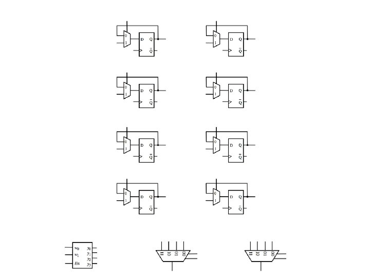
Complete the following circuit diagram to implement a register file with four 2 -bit registers, one write port, one read port, and one write enable line.
Register 0 Register 1 Register 2 Register 3
Register A Register B Register C Register D
A 1 A 0 B 1 B 0 C 1 C 0 D 1 D 0 Register A Register B Register C Register D
In 1 In 0 A 1 A 0 B 1 B 0 C 1 C 0 D 1 D 0 Register A Register B Register C Register D
In 1 Write_address_0 Write_address_1 Write_enable In 0 A 1 A 0 B 1 B 0 C 1 C 0 D 1 D 0 Register A Register B Register C Register D
In 1 Write_address_0 Write_address_1 Write_enable In 0 A 1 A 0 B 1 B 0 C 1 C 0 D 1 D 0 Register A Register B Register C Register D
In 1 Write_address_0 Write_address_1 Write_enable In 0 A 1 A 0 B 1 B 0 C 1 C 0 D 1 D 0 Register A Register B Register C Register D Read_address_1 Read_address_0 Out 1 Out
In 1 In 0 A 1 A 0 B 1 B 0 C 1 C 0 D 1 D 0 Register A Register B Register C Register D Clock Write_address_0 Write_address_1 Write_enable Read_address_1 Read_address_0 Out 1 Out
In 1 In 0 A 1 A 0 B 1 B 0 C 1 C 0 D 1 D 0 Clock Write_address_0 Write_address_1 Write_enable Read_address_1 Read_address_0 Out 1 Out
Another Register File
Register File • Register file is a unit containing r registers RA 1 RA 2 § r can be 4, 8, 16, 32, etc. • Each register has n bits § n can be 4, 8, 16, 32, etc. § n defines the data path width DATA 1 LD_DATA • Output ports (DATA 1 and DATA 2) are used for reading the register file § Any register can be read from any of the ports § Each port needs a log 2 r bits to specify the read address (RA 1 and RA 2) • Input port (LD_DATA) is used for writing data to the register file § Write address is also specified by log 2 r bits (WA) § Writing is enabled by a 1 -bit signal (WR) Reg File DATA 2 WR WA
Register File: Exercise • Suppose that a register file § contains 32 registers § width of data path is 16 bits (i. e. , each register has 16 bits) RA 1 DATA 1 LD_DATA • How many bits are there for each of the signals? § § § § RA 1 RA 2 DATA 1 DATA 2 WA LD_DATA WR 5 5 16 16 5 16 1 RA 2 Reg File DATA 2 WR WA
Register file design • We will design an eight-register file with 4 -bit wide registers • A single 4 -bit register and its abstraction are shown below LD D 3 D 2 D 1 D 0 LD 1 0 D Q P Q 3 1 0 D Q P Q 2 1 0 D Q P Q 1 1 0 D Q P Q 0 D 3 D 2 D 1 D 0 Q 3 Q 2 Q 1 Q 0 Clock • We have to use eight such registers to make an eight register file LD D 3 D 2 D 1 D 0 LD Q 3 Q 2 Q 1 Q 0 Clk D 3 D 2 D 1 D 0 Q 3 Q 2 Q 1 Q 0 Clk • How many bits are required to specify a register address?
Reading Circuit • A 3 -bit register address, RA, specifies which register is to be read • For each output port, we need one 8 -to-1 4 -bit multiplier Register Address 111 000 LD 7 D 3 D 2 D 1 D 0 LD 1 D 3 D 2 D 1 D 0 LD 0 D 3 D 2 D 1 D 0 Q 3 Q 2 Q 1 Q 0 Clk 7 6 5 4 3 2 1 0 RA 1 8 -to-1 4 -bit multiplex DATA 1 Clk 7 6 5 4 3 2 1 0 8 -to-1 4 -bit multiplex RA 2 DATA 2
Adding write control to register file • To write to any register, we need the register's address (WA) and a write register signal (WR) • A 3 -bit write address is decoded if write register signal is present • One of the eight registers gets a LD signal from the decoder LD_DATA WA 3 to 8 D e c o d e r LD 7 D 3 D 2 D 1 D 0 LD 1 D 3 D 2 D 1 D 0 LD 0 D 3 D 2 D 1 D 0 Q 3 Q 2 Q 1 Q 0 111 001 Clk LD 2 LD 1 LD 0 Clk 7 6 5 4 3 2 1 0 RA 1 8 -to-1 4 -bit multiplex 000 Clk 7 6 5 4 3 2 1 0 8 -to-1 4 -bit multiplex RA 2 WR DATA 1 DATA 2
Questions?
THE END