CPE 426 Computer Networks Week 3 Review 3


 MAC-48 Address In Transmission Order 01 -23 -45 -67")


 Using L 3 Switch")

 Note: ����")


")
 7 4 3 0 GFC")
")
 Flag 1 Flag: Indicates the start of a")
")

 RAS Internet")
![Importance Ethernet Standards Ethernet Date Standard Experimental 1973[1] Ethernet Description 2. 94 Mbit/s (367](https://slidetodoc.com/presentation_image_h/8138865d61f28b23924ddb89e3410003/image-44.jpg "Importance Ethernet Standards Ethernet Date Standard Experimental 1973[1] Ethernet Description 2. 94 Mbit/s (367")


- Slides: 69
CPE 426 Computer Networks Week 3: Review 3: SPT & VLAN Chapter 20: Internet Concept Chapter 21: IP Address
TOPICS n 1. Repeater/Bridges n n Chapter 17: 17. 1 -17. 6 2. SPT n Chapter 17: 17. 7 -17. 8 n 3. VLAN n Chapter 17: 17. 9 -17. 11 4. X. 25/FR/ATM/MPLS/ISDN n Chapter 19: 19. 1 -19. 4 ALSO Reference From CPE 326 (Stalling Book) n
TOPICS n n BREAK Chapter 20: Internetworking n n n Motivation: Sec. 20. 1 -20. 2 Concept: Sec. 20. 3 -20. 4 Internetworking: Sec. 20. 5 -20. 8 Protocol Architecture: Sec. 20. 9 -20. 11 Routers: Sec. 20. 12 Chapter 21: IP Address (Not Finish) n n Addressing Scheme/Prefix&Suffix: 21. 1 -21. 8 Subnetting and Mask: 21. 9 -21. 13
Ether Type II (DIX Frame) MAC-48 Address In Transmission Order 01 -23 -45 -67 -89 -ab, 01: 23: 45: 67: 89: ab, 0123. 4567. 89 ab 802. 3/. 4 Send LSBit First (Canonical Format) 10000000 11000100 10100010 … 802. 5/. 6 Send MSBit First (Bit-Reverse/Non-canonical) 00000001 00100011 01000101 …
Bridge vs Repeater: Collision Domain vs Broadcast Domain A E B F C D A B C Port 0 Port 1 G H Collision Domain Broadcast Domain E F G D H
Layer 2 Redundancy: Active Link S 4 L 2 Redundancy Access Switch S 5 Core Switch S 1 S 2 S 3
Layer 2 Redundancy: SPT S 4 L 2 Redundancy Access Switch S 5 Core Switch S 1 S 2 S 3
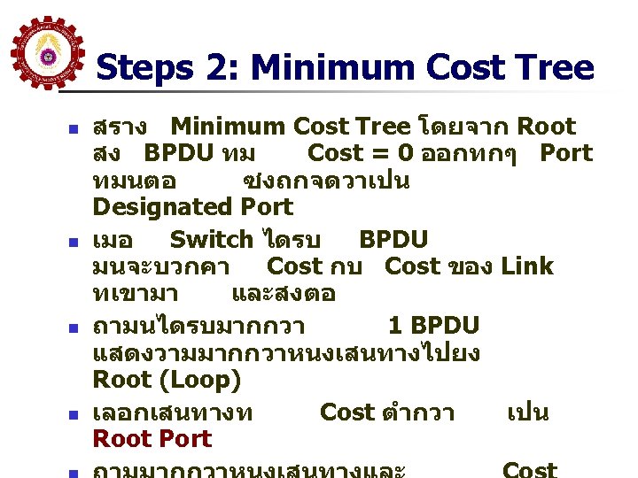
Steps 1: Root Bridge Selection n n เลอก Root Bridge โดยทก Switch สง BPDU ออกทก Port และใสคา Bridge ID = Bridge Priority(2 Octet) + MAC Address(6 Octet) Switch ทม Bridge ID ตำสดจะเปน Root Default Bridge Priority = 32768 ถาไมมการ Configure ดงนน Switch ทม MAC Address ตำสดจะไดรบเลอก
Order of Precedence ����� Root Bridge ID 28672; MAC 0123. 4567. 89 AB ID 32768; MAC 1234. 0000. ABCD ID 36864; MAC 2345. 0900. 0 AC 2 ID 28672; MAC FBEA. 4567. 0110 ID 32768; MAC ABCD. EF 01. 2345 ID 36864; MAC 234 A. F 0 F 2. A 023 ID 32768; MAC BCBD. A 012. 4 FFE ID 36864; MAC 67 AE. A 089. 86 A 2
Order of Precedence ID 28672; MAC 0123. 4567. 89 AB ID 32768; MAC 1234. 0000. ABCD ID 36864; MAC 2345. 0900. 0 AC 2 ID 28672; MAC FBEA. 4567. 0110 ID 32768; MAC ABCD. EF 01. 2345 ID 36864; MAC 234 A. F 0 F 2. A 023 ID 32768; MAC BCBD. A 012. 4 FFE ID 36864; MAC 67 AE. A 089. 86 A 2
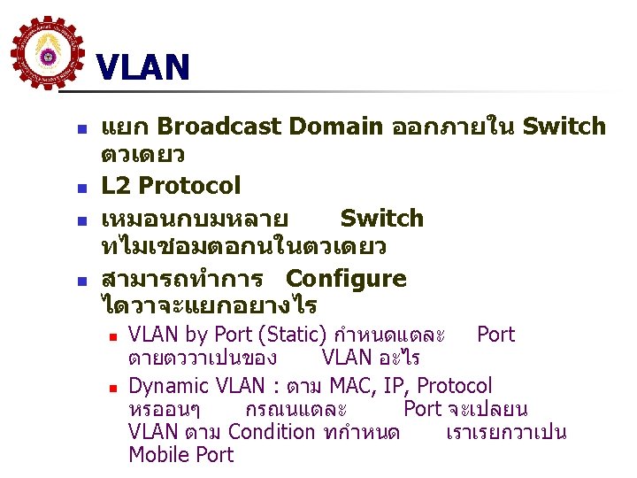
VLAN แบง Switch เปนหลายสวน Switch �������� VLAN ����� Managed Switch ����������� 3 VLAN 100 VLAN 200 VLAN 1 5/3 5/5 5/7 5/9 5/11 5/13 5/15 5/17 5/19 5/21 5/23 5/9 5/2 5/4 5/6 5/8 5/10 5/12 5/14 5/16 5/18 5/20 5/22 5/24 VLAN 100 PC 1 PC 2 192. 168. 10/24 192. 168. 20/24 PC 3 192. 168. 1. 10/24 PC 1 192. 168. 10/24 VLAN 200 VLAN 1 PC 2 192. 168. 20/24 PC 3 192. 168. 1. 10/24 ����� VLAN �������� Switch ������� Sub-network/Broadcast Domain ������� Layer 3(Router) ������
VLAN สามารถขยายผานมากกวา Switch Room 2 Room 1 VLAN 100 1 VLAN 200 VLAN 100 VLAN 200
VLAN สามารถขยายผานมากกวา Switch Room 1 1 Room 2 VLAN 100 VLAN 200
VLAN สามารถขยายผานมากกวา Switch 1 Room 2 Room 1 VLAN 100, 200 VLAN 100 VLAN 200
VLAN สามารถขยายผานมากกวา Switch Room 1 VLAN 100 1 Room 2 VLAN 100, 200 VLAN 100 VLAN 200
VLAN สามารถขยายผานมากกวา Switch Room 1 VLAN 200 1 Room 2 VLAN 100, 200 VLAN 100 VLAN 200
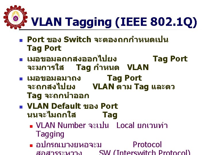
VLAN TAGGING n IEEE 802. 1 Q Standard n n n 4 Byte เพมในสวนของ Header 12 Bit เปน VLAN Number ISL(Cisco) n Encapsulation
Communication Between VLAN n n Connect Through Router (L 3) Using L 3 Switch ดกวา
WAN Connection
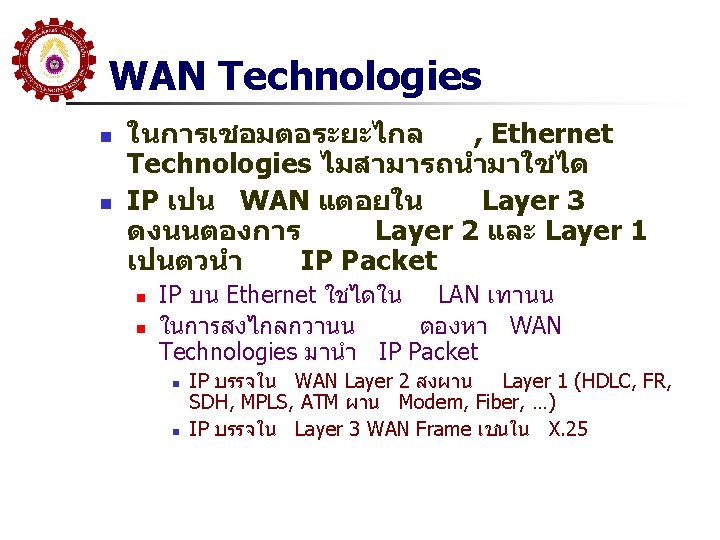
Connect to ISP Router Modem Router Leased Line Modem ISP (IP Network) Note: ���� Technology ��� Ethernet ���������� LAN ���������� Public Network
WAN Technologies
HDLC n n High Level Data Link Control Protocol ISO Standard n n Current Standard = ISO 13239 Connection Oriented and Connectionless Most common mode = point-to-point using ABM (Asynchronous Balanced Mode) Transmission Mode/Station Type/Flow n ดใน CPE 326 (Stalling Book)
HDLC Frame Format HDLC �������� Frame Format ��� L 2 Protocol ����� -LLC -MAC -PPP -LAPB -LAPD -LAPF -���
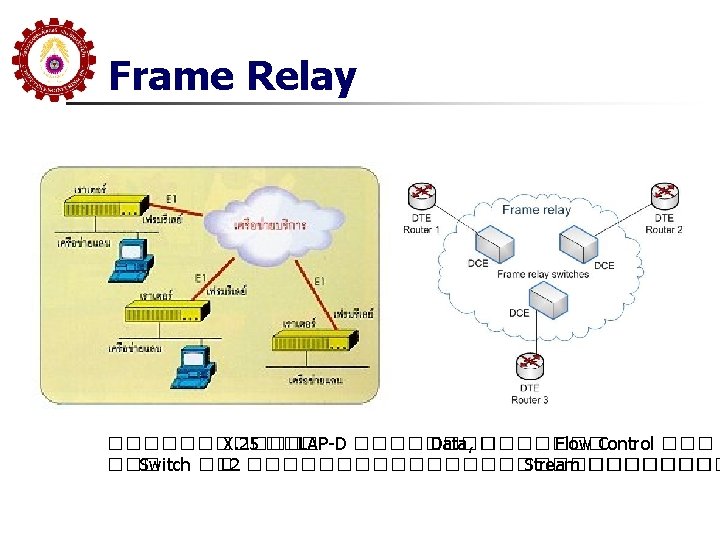
X. 25 Packet Switching Exchange Node
X. 25 n n n General Format ID Logical Channel ID -LC Group No -LC Number Packet Type ID Physical Layer: กำหนดการเชอมตอทางไฟฟา ระหวาง DTE/DCE จะอยใน X. 21 หรอจะใช EIA 232, EIA-449 หรอ Serial Protocol อน Data Link Layer: กำหนดขบวนการใช Link สำหรบการสงขอมลระหวาง DTE/DCE จะใช LAPB Packet Layer กำหนด Protocol ในระดบ Packet ในการแลกเปลยน Control และ Data กบ PSN ผาน Virtual Circuit
Diagram of the UNI ATM Cell ATM (Cell Switching)
Diagram of the UNI ATM Cell ATM (Cell Switching) 7 4 3 0 GFC VPI VCI VCI PT CLP ���� SDH ����� Transport ATM CBR VBR ABR UBR HEC Payload and padding if necessary (48 bytes) AAL Type 1 -5
MPLS (Multiprotocol Label Switching)
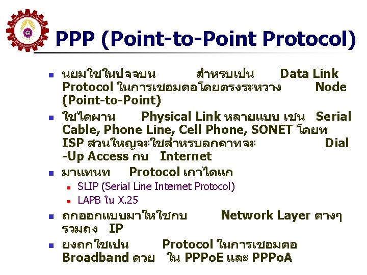
PPP Frame Field Name Size (bytes) Flag 1 Flag: Indicates the start of a PPP frame. Always has the value “ 01111110” binary (0 x 7 E hexadecimal, or 126 decimal. ( Address 1 Address: In HDLC this is the address of the destination of the frame. But in PPP we are dealing with a direct link between two devices, so this field has no real meaning. It is thus always set to “ 1111” (0 x. FF or 255 decimal), which is equivalent to a broadcast (it means “all stations. (” Control 1 Control: This field is used in HDLC for various control purposes, but in PPP it is set to “ 00000011” (3 decimal. ( Protocol 2 Protocol: Identifies the protocol of the datagram encapsulated in the Information field of the frame. See below for more information on the Protocol field. Information Variable Information: Zero or more bytes of payload that contains either data or control information, depending on the frame type. For regular PPP data frames the network-layer datagram is encapsulated here. For control frames, the control information fields are placed here instead. Padding Variable Padding: In some cases, additional dummy bytes may be added to pad out the size of the PPP frame. 2 (or 4) Frame Check Sequence (FCS): A checksum computed over the frame to provide basic protection against errors in transmission. This is a CRC code similar to the one used for other layer two protocol error protection schemes such as the one used in Ethernet. It can be either 16 bits or 32 bits in size (default is 16 bits). FCS Description The FCS is calculated over the Address , Control , Protocol , Information and Padding fields. Flag 1 Flag: Indicates the end of a PPP frame. Always has the value “ 01111110” binary (0 x 7 E hexadecimal, or 126 decimal. (
Broad-band (ADSL)
Application Transport Network FTP SMTP HTTP TCP DNS UDP IP IPv 6 PPP Network access … PPPo. E Ethernet … PPPo. E
PPPo. E ADSL Modem DSLAM Splitter Switch ADSL PSTN(SDH) RAS Internet
Importance Ethernet Standards Ethernet Date Standard Experimental 1973[1] Ethernet Description 2. 94 Mbit/s (367 k. B/s) over coaxial cable (coax) bus 1982 10 Mbit/s (1. 25 MB/s) over thick coax. Frames have a Type field. This frame format is used on all forms of Ethernet by protocols in the Internet protocol suite. IEEE 802. 3 standard 1983 10 BASE 5 10 Mbit/s (1. 25 MB/s) over thick coax. Same as Ethernet II (above) except Type field is replaced by Length, and an 802. 2 LLC header follows the 802. 3 header. Based on the CSMA/CD Process. 802. 3 a 1985 10 BASE 2 10 Mbit/s (1. 25 MB/s) over thin Coax (a. k. a. thinnet or cheapernet) 802. 3 i 1990 10 BASE-T 10 Mbit/s (1. 25 MB/s) over twisted pair 802. 3 j 1993 10 BASE-F 10 Mbit/s (1. 25 MB/s) over Fiber-Optic Ethernet II (DIX v 2. 0)
Importance Ethernet Standards Ethernet Standard Date Description 802. 3 u 1995 100 BASE-TX, 100 BASE-T 4, 100 BASE-FX Fast Ethernet at 100 Mbit/s (12. 5 MB/s) w/autonegotiation 802. 3 x 1997 Full Duplex and flow control; also incorporates DIX framing, so there's no longer a DIX/802. 3 split 802. 3 ab 1999 802. 3 ad 2000 1000 BASE-T Gbit/s Ethernet over twisted pair at 1 Gbit/s (125 MB/s) Link aggregation for parallel links, since moved to IEEE 802. 1 AX 802. 3 ae 2002 10 Gigabit Ethernet over fiber; 10 GBASE-SR, 10 GBASE-LR, 10 GBASE-ER, 10 GBASE-SW, 10 GBASELW, 10 GBASE-EW 802. 3 af 2003 Power over Ethernet (15. 4 W) 802. 3 an 2006 10 GBASE-T 10 Gbit/s (1, 250 MB/s) Ethernet over unshielded twisted pair (UTP) 802. 3 at 2009 Power over Ethernet enhancements (25. 5 W)
Ethernet Standard Date Description 2010 40 Gbit/s and 100 Gbit/s Ethernet. 40 Gbit/s over 1 m backplane, 10 m Cu cable assembly (4 x 25 Gbit or 10 x 10 Gbit lanes) and 100 m of MMF and 100 Gbit/s up to 10 m of Cu cable assembly, 100 m of MMF or 40 km of SMF respectively 802. 3. 1 2011 MIB definitions for Ethernet. It consolidates the Ethernet related MIBs present in Annex 30 A&B, various IETF RFCs, and 802. 1 AB annex F into one master document with a machine readable extract. (workgroup name was P 802. 3 be) 802. 3 bm 2015 ~Feb 2016 802. 3 ba 802. 3 bq 100 G/40 G Ethernet for optical fiber 40 GBASE-T for 4 -pair balanced twisted-pair cabling with 2 connectors over 30 m distances 400 Gbit/s Ethernet over optical fiber using multiple 25 G/50 G lanes 802. 3 bs ~ 2017 802. 3 by ~Sep 2016 25 G Ethernet 802. 3 bz TBD 2. 5 Gigabit and 5 Gigabit Ethernet over twisted pair - 2. 5 GBASE-T and 5 GBASE-T
n n n END OF REVIEW BREAK CHAPTER 20: TCP/IP Concept
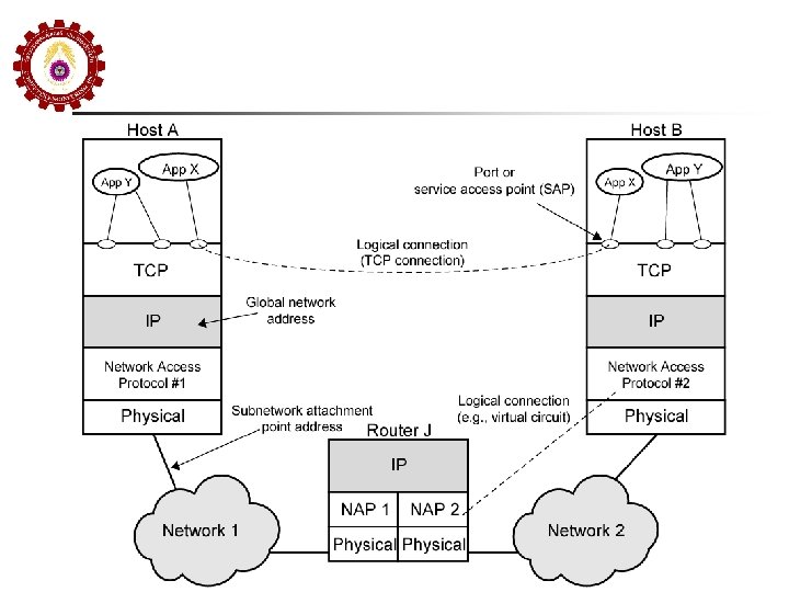
Chapter 20: Internetworking with Router Link 1 Link 2 phy 1 phy 2 NW 1: NW 2: Router Address/frame/signal/media An internet ����� NW ������������ Router
Chapter 20: Internet Architecture มกจะใช Partial Mesh เพอสราง Redundancy ในการสงขอมล n NW 2: NW 1: NW 3: NW 6: NW 5: NW 4: NW 7: PSN NW 9: NW 8: LAN
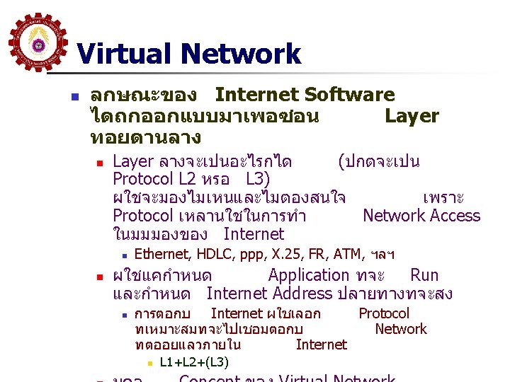
Virtual Network ATM Ethernet X. 25 x. 21 NW 2: NW 1: NW 3: ppp NW 7: X. 25 x. 21 NW 6: Virtual Network NW 5: NW 4: NW 8: ATM NW 9: FR (LAPD) ppp FR (LAPD) Concept ��� The Internet ����������� Internet ���� Network Access Protocol ����������������� Network �������� Internet ���������������������� ISP (Internet Service Provid ��������������
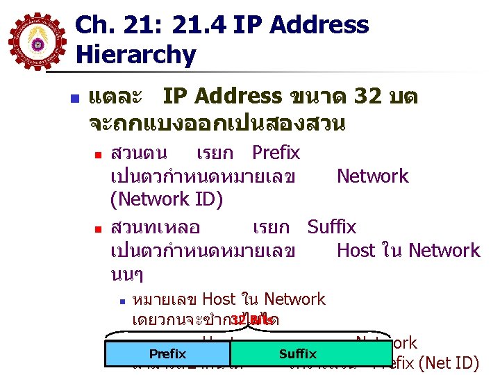
Ch. 21: 21. 4 IP Address Hierarchy Network # 1 1 Net ID Host # 1 Network # 2 Network # 3 6 Host ID
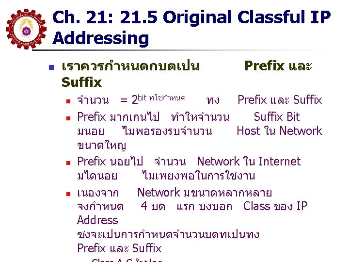
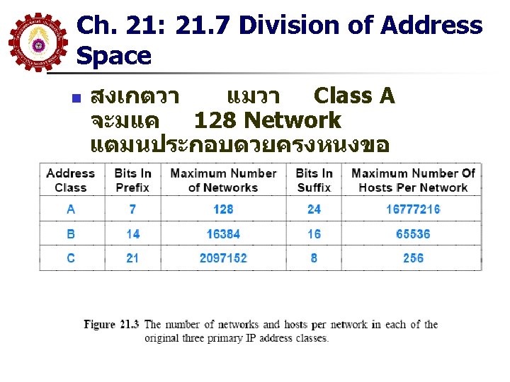
Ch. 21: 21. 5 Original Classful IP Addressing
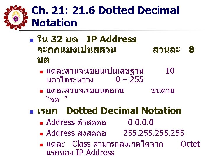
Ch. 21: 21. 6 Dotted Decimal Notation
Ch. 21: 21. 8 Authority for Address n องคกรทดแลจดการเรอง Address คอ ICANN n n n IP Internet Corporation for Assigned Names and Numbers ปกต ICANN จะกำหนดให Registrar เปนผจดสรรในแตละภมภาคอ กทหนง Registrar จะจดสรร Block ของ IP Address ใหแก ISP แตละราย
Summary of IP Classful octet 1 octet 2 Network ID Class A: 1 to 127 Host ID 0 to 255 Network ID Class B: 128 to 191 192 to 223 Range of addresses 0 to 255 1. 0. 0. 0 to 127. 255 0 to 255 128. 0. 0. 0 to 191. 255 Host ID 0 to 255 Network ID Class C: octet 4 octet 3 0 to 255 Host ID 0 to 255 1 to 254 192. 0. 0. 0 to 223. 255 Multicast address Class D (multicast): 224 to 239 0 to 255 1 to 254 224. 0. 0. 0 to 239. 255 Class E (reserved): 240 to 255 1 to 254 240. 0 to 255