
Counters A counter is a device which stores
- Slides: 17
Counters A counter is a device which stores (and sometimes displays) the number of times a particular event or process has occurred, often in relationship to a clock signal. Counters are categorized as: Ø Ø Asynchronous (Ripple) Counters - the flip-flop output serves as a source for triggering other flip-flops. Ø Synchronous Counters - the input pulses are applied to all CP inputs of all flip-flops. The change of state of a particular flip-flop is dependent CP on the present state
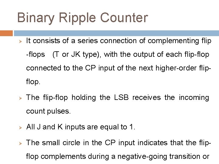
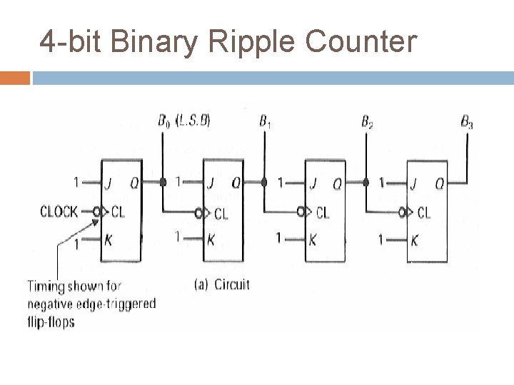
Binary Ripple Counter Ø It consists of a series connection of complementing flip -flops (T or JK type), with the output of each flip-flop connected to the CP input of the next higher-order flipflop. Ø The flip-flop holding the LSB receives the incoming count pulses. Ø All J and K inputs are equal to 1. Ø The small circle in the CP input indicates that the flipflop complements during a negative-going transition or
4 -bit Binary Ripple Counter
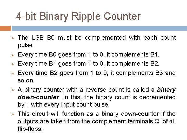
4 -bit Binary Ripple Counter Ø Ø Ø The LSB B 0 must be complemented with each count pulse. Every time B 0 goes from 1 to 0, it complements B 1. Every time B 1 goes from 1 to 0, it complements B 2. Every time B 2 goes from 1 to 0, it complements B 3 and so on. A binary counter with a reverse count is called a binary down-counter. In this, the binary count is decremented by 1 with every input count pulse. This circuit will function as a binary down-counter if the outputs are taken from the complement terminals Q’ of all flip-flops.
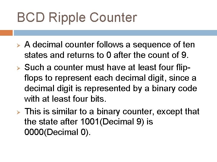
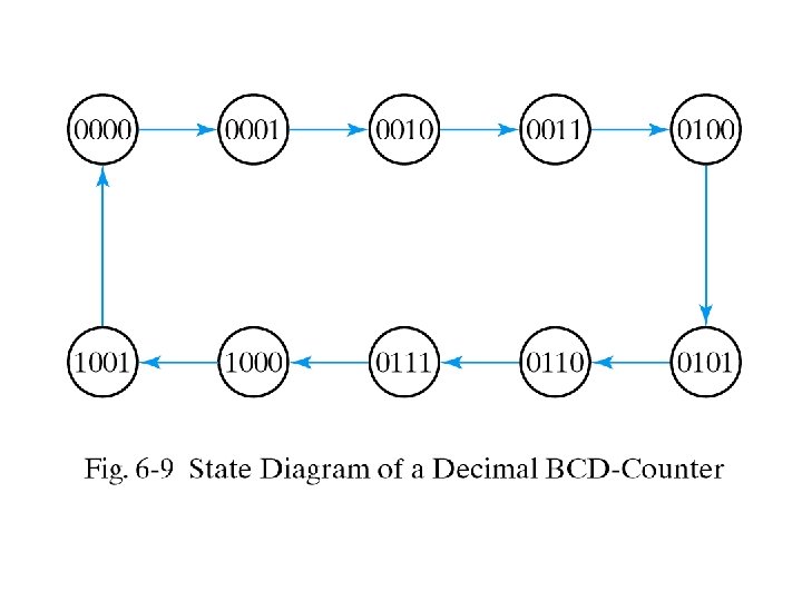
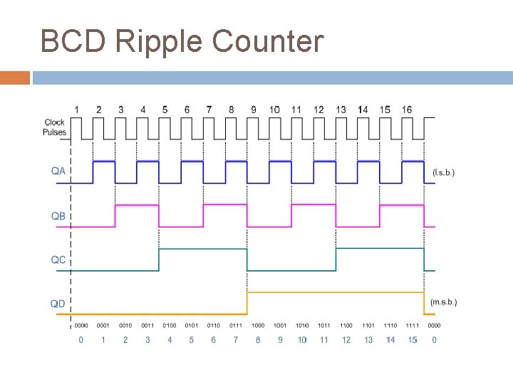
BCD Ripple Counter Ø Ø Ø A decimal counter follows a sequence of ten states and returns to 0 after the count of 9. Such a counter must have at least four flipflops to represent each decimal digit, since a decimal digit is represented by a binary code with at least four bits. This is similar to a binary counter, except that the state after 1001(Decimal 9) is 0000(Decimal 0).
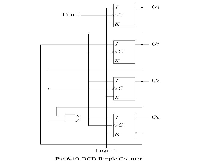
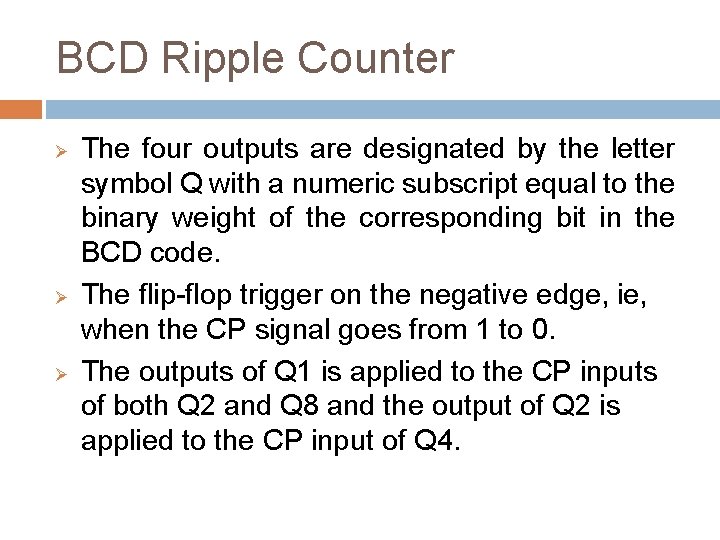
BCD Ripple Counter Ø Ø Ø The four outputs are designated by the letter symbol Q with a numeric subscript equal to the binary weight of the corresponding bit in the BCD code. The flip-flop trigger on the negative edge, ie, when the CP signal goes from 1 to 0. The outputs of Q 1 is applied to the CP inputs of both Q 2 and Q 8 and the output of Q 2 is applied to the CP input of Q 4.
BCD Ripple Counter
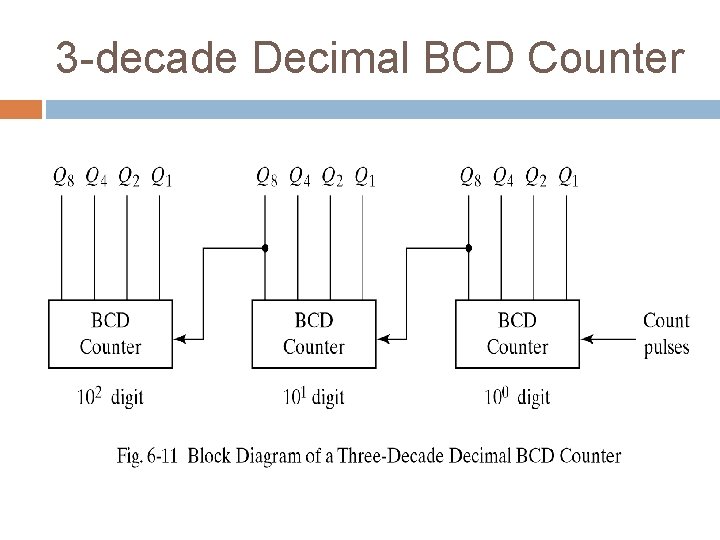
BCD Ripple Counter Ø Ø It is known as decade counter, since it counts from 0 to 9. To count in decimal from 0 to 99, we need a two-decade counter. To count in decimal from 0 to 999, we need a three-decade counter. Multiple-decade counters can be constructed by connecting BCD counters in cascade, one for each decade.
3 -decade Decimal BCD Counter
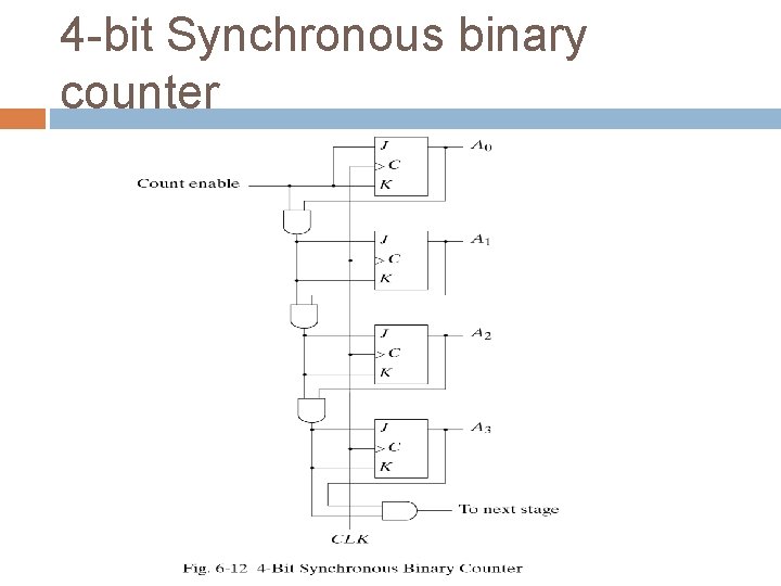
SYNCHRONOUS COUNTERS In synchronous binary counter, clock pulses are applied to the CP inputs of all flip-flops and triggered simultaneously. If J = K = 0, the flip-flop remains unchanged. If J = K = 1, the flip-flop complements. For example, complemented. the first flip-flop A 0 is always A 1 is complemented when the present state of A 0 is 1. A 2 is complemented when present state of A 1 A 0=11. A 3 is complemented when present state of A 2 A 1 A 0=111.
4 -bit Synchronous binary counter
4 -bit Synchronous binary counter Ø The CP terminals of all flip-flops are connected to a common clock-pulse source. Ø The first stage A 0 has its J and K equal to 1 if the counter is enabled.
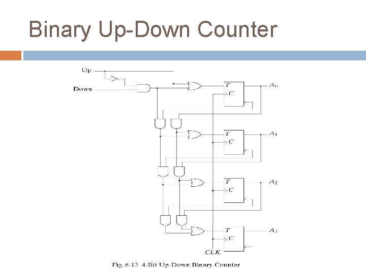
Binary Up-Down Counter A synchronous count down binary counter goes through the binary states in the reverse order from 1111 down to 0000 and back to 1111 The least significant bit is always complemented. Each bit is complemented if all the lower bits are equal to 0 The two operations can be combined in one circuit to form a counter capable of counting either up or down When up and down inputs are 0, the circuit does not change state and when there are both 1, the circuit counts up.
Binary Up-Down Counter
Binary Up-Down Counter Ø Ø Ø When the up input control is 1, the circuit counts up, since the T inputs are determined from the previous values of the normal outputs in Q. When the down input control is 1, the circuit counts down, since the complement outputs Q’ determine the states of the T inputs. When both the up and down signal are 0’s, the register does not change state but remains in the same count.