
COP 3502 Introduction to Computer Science Hardware Yashas
- Slides: 15
COP 3502: Introduction to Computer Science Hardware Yashas Shankar
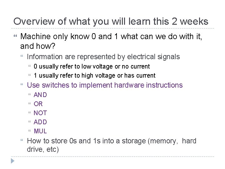
Overview of what you will learn this 2 weeks Machine only know 0 and 1 what can we do with it, and how? Information are represented by electrical signals Use switches to implement hardware instructions 0 usually refer to low voltage or no current 1 usually refer to high voltage or has current AND OR NOT ADD MUL How to store 0 s and 1 s into a storage (memory, hard drive, etc)
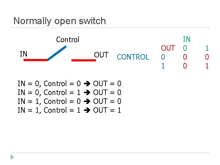
Normally open switch Control IN IN IN OUT = = 0, 0, 1, 1, Control = = 0 1 OUT OUT CONTROL = = 0 0 0 1 OUT 0 1 IN 0 0 0 1
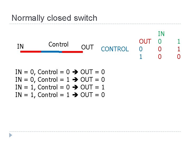
Normally closed switch Control IN IN IN = = 0, 0, 1, 1, Control = = 0 1 OUT OUT OUT CONTROL = = 0 0 1 0 OUT 0 1 IN 0 0 0 1 1 0
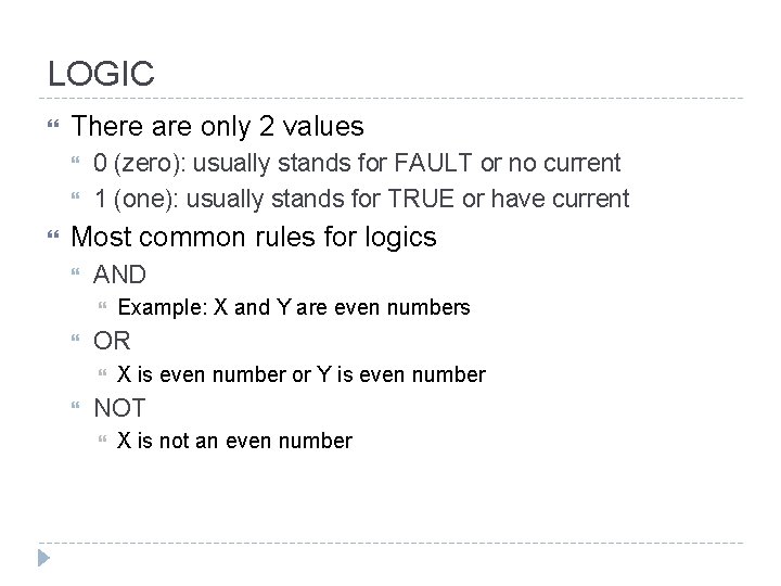
LOGIC There are only 2 values 0 (zero): usually stands for FAULT or no current 1 (one): usually stands for TRUE or have current Most common rules for logics AND OR Example: X and Y are even numbers X is even number or Y is even number NOT X is not an even number
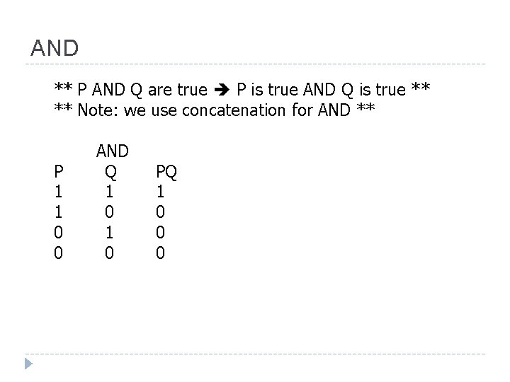
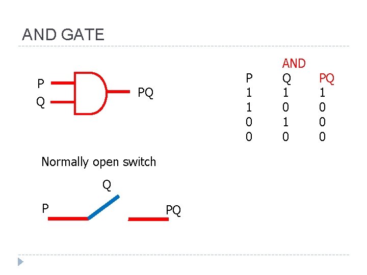
AND ** P AND Q are true P is true AND Q is true ** ** Note: we use concatenation for AND ** P 1 1 0 0 AND Q 1 0 PQ 1 0 0 0
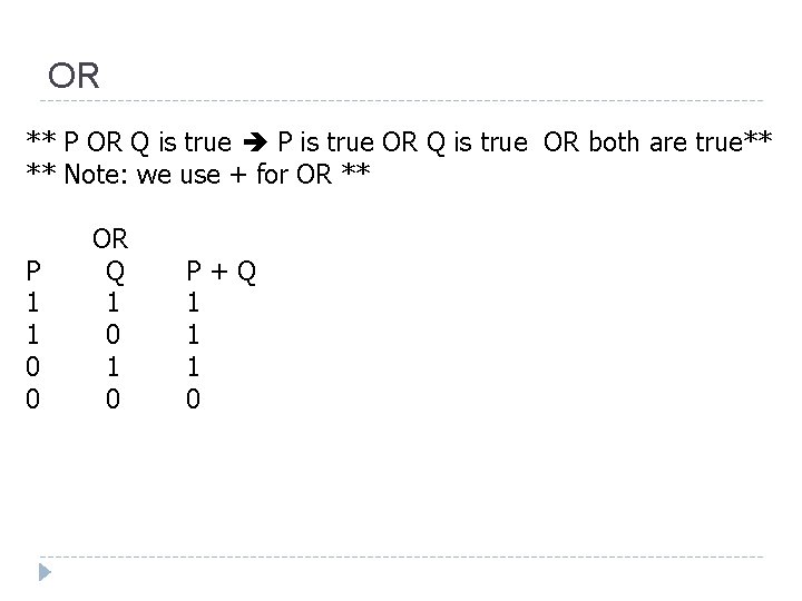
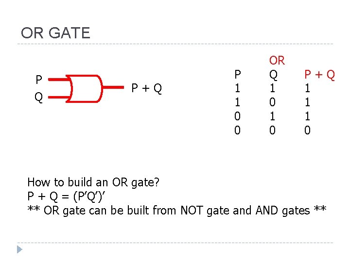
OR ** P OR Q is true P is true OR Q is true OR both are true** ** Note: we use + for OR ** P 1 1 0 0 OR Q 1 0 P+Q 1 1 1 0
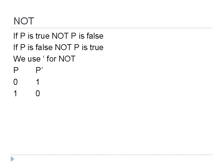
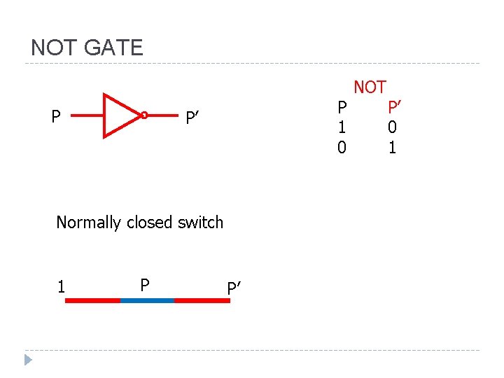
NOT If P is true NOT P is false If P is false NOT P is true We use ‘ for NOT P P’ 0 1 1 0
AND GATE P Q P 1 1 0 0 PQ Normally open switch Q P PQ AND Q 1 0 PQ 1 0 0 0
NOT GATE P P 1 0 P’ Normally closed switch 1 P P’ NOT P’ 0 1
OR GATE P Q P+Q P 1 1 0 0 OR Q 1 0 P+Q 1 1 1 0 How to build an OR gate? P + Q = (P’Q’)’ ** OR gate can be built from NOT gate and AND gates **
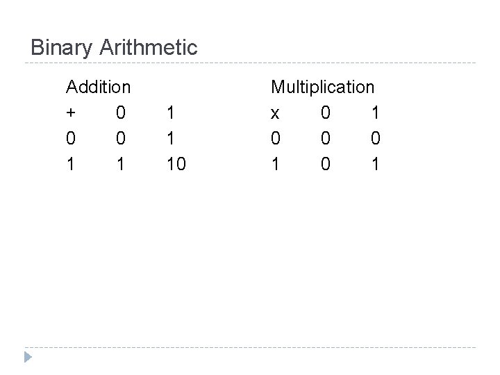
Binary Arithmetic Addition + 0 0 0 1 1 10 Multiplication x 0 1 0 0 0 1
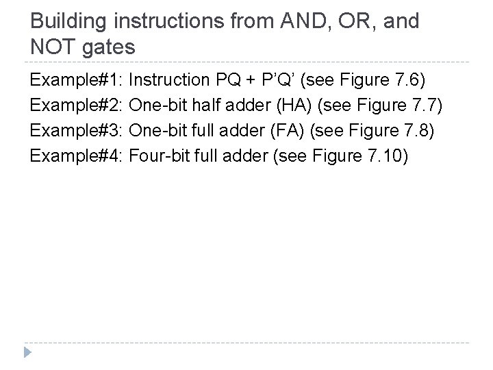
Building instructions from AND, OR, and NOT gates Example#1: Instruction PQ + P’Q’ (see Figure 7. 6) Example#2: One-bit half adder (HA) (see Figure 7. 7) Example#3: One-bit full adder (FA) (see Figure 7. 8) Example#4: Four-bit full adder (see Figure 7. 10)
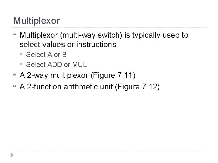
Multiplexor (multi-way switch) is typically used to select values or instructions Select A or B Select ADD or MUL A 2 -way multiplexor (Figure 7. 11) A 2 -function arithmetic unit (Figure 7. 12)
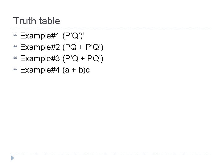
Truth table Example#1 (P’Q’)’ Example#2 (PQ + P’Q’) Example#3 (P’Q + PQ’) Example#4 (a + b)c