Coordination Chemistry III Electronic Spectra Chapter 11 Coordination


 • 2 S+1 L – L and S relate to the")


![Overall Spin Quantum Number, S • Magnitude of the spin angular momentum is [S(S+1)]1/2(h/2](https://slidetodoc.com/presentation_image_h/fa2eae3528c1e0b50be16f6c08031f52/image-10.jpg "Overall Spin Quantum Number, S • Magnitude of the spin angular momentum is [S(S+1)]1/2(h/2")


 has the highest")

 that")


![A 2 d Configuration, [V(H 2 O)6 3+ ]](https://slidetodoc.com/presentation_image_h/fa2eae3528c1e0b50be16f6c08031f52/image-28.jpg "A 2 d Configuration, [V(H 2 O)6 3+ ]")


![Jahn-Teller Distortions • Spectrum of the [Ti(H 2 O)6]3+ complex. – The complex has](https://slidetodoc.com/presentation_image_h/fa2eae3528c1e0b50be16f6c08031f52/image-32.jpg "Jahn-Teller Distortions • Spectrum of the [Ti(H 2 O)6]3+ complex. – The complex has")


- Slides: 34
Coordination Chemistry III: Electronic Spectra Chapter 11
Coordination Complexes • Unlike most organic compounds, many coordination compounds have vivid colors. – These vivid colors are due to the electronic transitions between the d-orbitals of the metal. • The energy levels of d electron configurations, however, are usually more complicated than might be expected since the electrons in the atomic orbitals interact with each other.
Absorption of Light • Complementary colors – if a compound absorbed light of one color, the complement of that color is observed. – [Cu(H 2 O)6]2+ has a blue color. What is absorbed? • Beer-Lambert Absorption Law • log(Io/I)=A= lc (define variables) • In a common absorption spectrum, the A is plotted versus wavelength or cm-1 (1/ ).
Quantum Numbers of Multielectron Atoms • In order to understand energy transitions between states with more than one electron, we need to understand in more detail how these electrons interact with each other. • Each conceivable set of individual ml and ms values constitutes a microstate of the configuration. – How many microstates in a d 1 configuration? – Examine the carbon atom (p 2 configuration) • Determine the electron configuration and quantum numbers. • Independently, each of the 2 p electrons could have one of six possible combinations. The two electrons, however, are not independent of each other.
Interaction between Electrons • In any microstate, the individual orbital magnetic moments (related to ml) and the spin magnetic moments (related to ms) will interact resulting in an energy state or term for the configuration. – Commonly, a number of microstates will contribute to a single term (degeneracies). • This is an approximation using the one-electron wave mechanical mode. – Works well for 1 st and 2 nd row transition metals.
Term Designation (Free-Ion) • 2 S+1 L – L and S relate to the overall orbital and spin angular momenta for the system (or state). – L = overall orbital angular momentum quantum number. • Discuss possible values (analogous to the l quantum number). • L is related to the vectorial addition of vectors taken from the l quantum number. • Discuss the permitted ways in which the l values can combine (Figure 20, Carter).
Overall Orbital Angular Momentum Quantum Number, L • The vectorial addition produces the possible terms for a given configuration. • For a given term, the magnitude of the resultant angular momentum is fixed, [L(L+1)]1/2(h/2 ). • The vector for the momentum can have a number of allowed orientations. – A partial lift of degeneracy by the magnetic field. – Allowed orientations for a given term are associated with the overall magnetic quantum number, ML. • ML = L, L-1, …. -L
Overall Orbital Angular Momentum Quantum Number, L • ML relates to the orbital multiplicity or orbital degeneracy (Each has projection equal in magnitude to ML(h/2 )). – What are the allowed orientations for a D term? • In the Russell-Saunders scheme, ML = ml. – An ML value can be assigned to each microstate. • Therefore, a given L value must arise from a complete set of microstates with the 2 L+1 values. – Examples
Overall Spin Quantum Number, S • Spin state of the term. • 2 S+1 – spin multiplicity of the state. – S=0, 1, 2 • Like L, S can be obtained by vectorial addition of the spin angular momentum vectors (related to s or ms). – Magnitude [S(S+1)]1/2(h/2 ) • S is related to an overall spin quantum number, MS. – MS = S, S-1, …-S (2 S+1 values) – Indicates the ‘allowed’ orientations of the vector relative to an applied magnetic field. The produces the spin degeneracy in a spin state.
Overall Spin Quantum Number, S • Magnitude of the spin angular momentum is [S(S+1)]1/2(h/2 ), but its projections on a particular axis in the allowed orientation are given by MS(h/2 ). – Russell-Saunders scheme, MS= ms
In Summary • Any given term with L and S values arises from a set of microstates that has the necessary 2 L+1 values of ML and also the necessary 2 S+1 values of MS. • Value of the term – L = largest possible value of ML • Let’s do the d 2 configuration.
Determining Microstates • Determine the number of microstates for a triplet P. What are the allowed ML and MS values? • Determine the number of microstates for a doublet D. What are the allowed ML and MS values? – It is sufficient to designate the microstates by x (only the number is important). • Number of microstates in a given free-ion term is equal to (2 L + 1)(2 S +1). – Row multiplied by column
Reducing a Microstate Table/Configuration into Its Free-Ion Terms • Notice that each term is composed of a rectangular array of microstates. – This process is shown for a p 2 configuration in Table 11 -4. – The spin multiplicity is same as the number of columns of microstates. – The # of rows to include in the rectangular array is equal to +L -L (number of values). • (2 L+1)(2 S+1) Do the p 2 and d 2 configurations.
Term of the Lowest Energy • The ground term (lowest energy) has the highest spin multiplicity. • If two or more terms share the same maximum spin multiplicity, the ground term is the one having the highest L value. What is the term with the lowest energy for the d 2 configuration?
Spin-Orbit Coupling • There is also spin-orbit coupling wherein the spin and orbital angular momenta couple with each other. J = L+S, L+S-1, L+S-2, …. L-S| (no negative values) J is a subscript on the right side of the L quantum # – Determine the spin-orbit coupling in the 1 S and 3 P free-ion terms. Designate these with J. • Page 388
Lowest Energy Term Including Spin-Orbit Coupling • For subshells (such as p 2) that are less than half -filled, the state having the lowest J value has the lowest energy. For subshells that are more than half-filled, the state having the highest J value has the lowest energy. – Determine the lowest energy state for the p 2 configuration.
Electronic Spectra of Coordination Compounds • Absorption spectra in most cases involve the d orbitals of the metal. • Identifying lowest energy term (quickly) – Sketch the energy levels showing the d electrons. – Spin multiplicity of lowest-energy state equal highest possible number of unpaired electrons +1. – Determine the maximum possible value of ML ( ms) for the configuration. – Combine steps. High- and low-spin d 6 configurations in octahedral symmetry.
Reducing the Symmetry of the Free Ion by a Ligand Field • The orbital term symbols for the free atom/ion are identical to the symbols for the appropriate symmetry species in the spherical group, R 3 (show Table). – There are no inherent symmetry restrictions on possible orbital degeneracies. • D – fivefold degeneracy (ML = ? ) • F – ? ? ?
Correlation Table
Reducing the Symmetry of the Free Ion by a Ligand Field • When a ligand field is imposed, however, there are restrictions placed on the maximum orbital degeneracy. – In an octahedral complex, the maximum degeneracy is 3 (Ttype IR’s, look at table). Orbital degeneracies present in the free ion must be split. • All term symbols will be redefined by the new symmetry. • Upon reducing the symmetry, the free-ion term can be treated as a reducible representation composed of irreducible representations in the appropriate character table.
Reducing the Symmetry of the Free Ion by a Ligand Field • The total number of microstates, Dt, remains the same. • Do the d 1 configuration. – What does this split into when an octahedral field is imposed? – How many microstates are possible when imposing the ligand field? The new ligand-field terms will retain the original spin multiplicities found in the free-ion terms. Examine
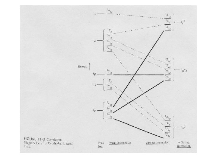
Correlation Diagrams – Relating Electron Spectra to Ligand Field Splitting • Examine the correlation diagram for a d 2 configuration in an octahedral ligand field. – Far left (absence of ligand field) – the free-ion terms. On this side, the ligand field has very little influence. • Examine the previous table. – Far right (strong ligand field) – the states are largely determined by the ligand field. • Observed before in the crystal field and ligand field discussion. • In real compounds, the situation is somewhere in the middle.
Splitting of Free-Ion Terms • Irreducible representations are produced. – Examine the correlation diagram and the Oh table. • Table 11 -6 – Each state has symmetric characteristics of that IR. – IRs are also obtained from the strong-field limit configurations (right side of table). • The IRs on the right and left sides must ‘correlate’.
Selection Rules for Transitions • Transitions between states of the same parity are forbidden. – Laporte Selection Rule • Transitions between states of different spin multiplicities are forbidden. 4 T and 4 A 2 1 2 2 Discuss how the rules are relaxed on the expected absorption intensities. – 4 A
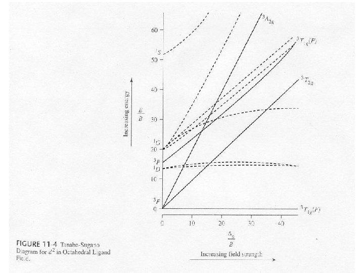
Tanabe-Sugano Diagrams • Special correlation diagrams useful in the interpretation of electronic spectra. – Lowest energy state is plotted along the horizontal axis. • o/B (field strength) – Vertical axis is the measure of the energy above the ground state • E/B B = Racah parameter, a measure of the repulsion between terms of the same multiplicity. – Lines connecting states of the same symmetry cannot cross.
A 2 d Configuration, [V(H 2 O)6 3+ ]
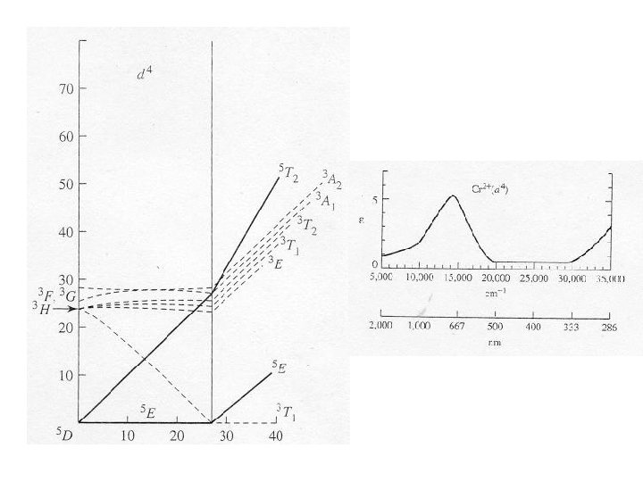
Electron Configurations • The diagrams of d 2 -d 8 are illustrated in Figure 11 -7. • There is a vertical line near the center of d 4 -d 7 diagrams. What does the vertical line represent? What happens once the line is crossed? • In some cases, the absorption bands are off-scale (x-axis) or obscured by the charge-transfer bands (discussed later). • Discuss the terms for the configurations. They are not the same as observed for the orbital terms.
Jahn-Teller Distortions • Spectrum of the [Ti(H 2 O)6]3+ complex. – The complex has a d 1 configuration (Fig. 11 -8). – Go over terms for the configurations. – Why are there two overlapping bands? • If degenerate orbitals are asymmetrically occupied a distortion will occur to remove the degeneracy. • Jahn-Teller distortion is usually only significant for asymmetrically occupied eg orbitals. – The others cannot be resolved. – The most common distortion is along the z-axis (elongation).
Symmetry Labels for Configurations • Symmetry labels for electron configurations match their degeneracies. – T = triply degenerate asymmetrical state – E = doubly degenerate asymmetrical state – A or B = nondegenerate Do a few without Jahn Teller splitting/distortion. • Effect of a D 4 h field.