Cooperative Communication Fundamental Limits and Enabling Technologies Behnaam

Cooperative Communication: Fundamental Limits and Enabling Technologies Behnaam Aazhang Center for Multimedia Communication and Department of Electrical and Computer Engineering at Rice University

Rice University u $2. 9 billion endowment u 530 faculty, 2800 undergraduates, 1950 graduate students (5: 1 undergrad student/faculty ratio) u Highest % National Merit Scholars u Educational value ranked 1 st – Kiplinger’s u 10 faculty – National Academy of Sciences u 12 faculty – National Academy of Engineering u 2 Nobel Prize winners
")
George R. Brown School of Engineering u u u 8 academic departments (91 faculty) – Bioengineering – Chemical Engineering – Civil and Environmental Engineering – Computational and Applied Mathematics – Computer Science – Electrical and Computer Engineering – Mechanical Engineering and Materials Science – Statistics 825+ undergraduates, 450+ graduate students Over $24 M/year in research expenditures

Electrical and Computer Engineering u u u 45 faculty (20 tenured/tenure track with primary ECE) – 8 of 20 IEEE Fellows Number of graduate students ( ~ 130) More than $12. 3 M won in grants in 2003 Major research centers – Center for Multimedia Communications – MURI Center for Nanoshell Design – Networking Research Group – Dynamical Systems Group – DSP Group Texas Instruments Leadership University The Connexions project

Wireless Communication u Market needs – Pervasive communication n Any time n Any where n Under most conditions – Inexpensive access – Support for all applications

Needs to Challenges in the Physical Layer u u Battery life – Power efficiency Spectrum cost – Spectral efficiency Reliability over fading channels – Diversity – Coding – ARQ Integrated services – Variable/Adaptive Qo. S – Rate control

By Now Conventional Approaches u u Explore degrees of freedom – Spatial – Temporal – Spectral Techniques – Space time coding – MIMO Trans. – Diversity – Coding Rec.

More Enablers u u Advanced signal processing – Equalization – Multiuser detection Avoid dichotomies – Source and channel coding – Joint MAC-PHY design – Scheduling Application layer Network layer (RRC) Data link layer (MAC) Physical layer

Another Look u Cooperative communication – Relay – User cooperation – Spectrum sharing All IP Backbone

A Broader View u Network is the channel – Routing – Physical channel modeling

Outline u u u Overview User cooperation Relay – Protocol – Power control – Code design Research hardware platforms – TAP Conclusions
![Historical Account u u Relay channels introduced in 1971 [Van der Meulen] Degraded assumption](http://slidetodoc.com/presentation_image_h/bbd173c3fde4c88ee243440941c3800d/image-12.jpg "Historical Account u u Relay channels introduced in 1971 [Van der Meulen] Degraded assumption")
Historical Account u u Relay channels introduced in 1971 [Van der Meulen] Degraded assumption added in 1979 [Cover&El Gamal] p(Y 1 , Y 0 | X 1 , X 2) = p(Y 1 | X 1 , X 2 ) p(Y 0 | X 2 , Y 1 ) Isolated work in the 80 s and 90 s Recent resurgence Y 1 R S X 1 X 2 D Y 0
![A More General Configuration u Two relays [Shein & Gallager] R D S R](http://slidetodoc.com/presentation_image_h/bbd173c3fde4c88ee243440941c3800d/image-13.jpg "A More General Configuration u Two relays [Shein & Gallager] R D S R")
A More General Configuration u Two relays [Shein & Gallager] R D S R u Multi-hop networks [Gupta&Kumar, Gastpar&Vetterli, Reznik&Verdu] R S R R D
![User Cooperation Diversity u u A multiuser perspective Cooperate for diversity [Sendonaris&Erkip&Aazhang] – Independent](http://slidetodoc.com/presentation_image_h/bbd173c3fde4c88ee243440941c3800d/image-14.jpg "User Cooperation Diversity u u A multiuser perspective Cooperate for diversity [Sendonaris&Erkip&Aazhang] – Independent")
User Cooperation Diversity u u A multiuser perspective Cooperate for diversity [Sendonaris&Erkip&Aazhang] – Independent fading – User 2 n Transmit own packets n Relay User 1 packets U 2 – Causal CDMA protocol Code design: RCPC U 1 D

Relay u u Relaying protocol Power control Code design Joint decoding at the destination Y 1 R X 2 S X 1 D Y 0

Relay Channel Model u Channel quality Z 0 Source h 10 X 1 h 12 Y 1 = h 12 X 1+ Z 1 Destination Y 0= h 10 X 1+ h 20 X 2+ Z 0 Z 1 h 20 X 2 Relay

Decode and Forward Relay u Decode u Forward u Block Markov encoding Doubly infinite codeword length Limited by the S to R link u u Y 1 R X 2 S X 1 D Y 0

Estimate and Forward Relay u u Estimate and forward for DMC [Cover & El Gamal] Generalization to Gaussian [Khojastepour&Sabharwal&Aazhang] – – Estimate Y 1 and forward Decode with Y 0 with side information Effective when R to D is a good channel Doubly infinite codeword lengths Y 1 R X 2 S X 1 D Y 0

Amplify and Forward Relay u Amplify and forward [Laneman &Tse& Wornel / Gastper & Vetterli / Mitra&Sabharwal] – – Simply infinite codeword lengths Will not outperform E-F and D-F Y 1 R X 2 S X 1 D Y 0

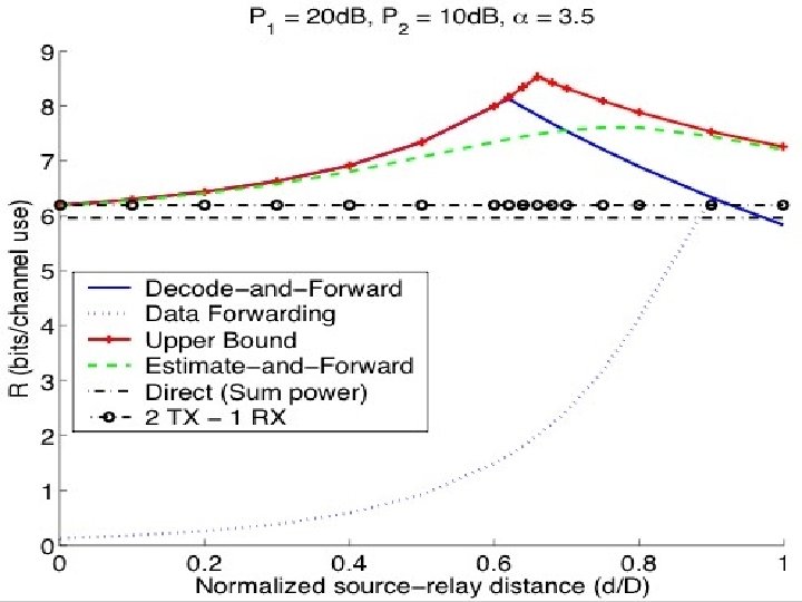
Numerical Results u u u Rayleigh fading Path loss Probability of outage and achievable rates Source Destination Relay d D

=3, R=1, Pavg = -1 d. B 0 Pout 10 -1 10 • direct transmission • amplify and forward • estimate and forward. • decode and forward • hybrid • outage lower bound • multi-hop -2 10 0 0. 2 0. 4 0. 6 Distance: d 0. 8 1

A Fundamental Assumption u u Relay user can receive while transmitting – Relay systems [Cover&El Gamal] – User cooperation Expensive to implement Y 1 R X 2 S X 1 D Y 0

Cheap Radios for Relay u Receive and transmit – Different time slots – Different spectrum S D Y 0 X 1 S D X 1 Y 0 Y 2 R Broadcast State X 2 R Multiple Access state

Numerical Results 0. 8 UB Expensive UB Cheap DF Expensive DF Cheap EF Expensive EF Cheap SF Cheap R (bits/channel use) 0. 7 0. 6 0. 5 0. 4 0. 3 0. 2 0. 1 0 0 0. 1 0. 2 0. 3 0. 4 0. 5 Input power 0. 6 0. 7 0. 8 0. 9 1

Power Control for Relay Channels u Fading channels with relay State of the network u Power assignments P and Prel u Y 1 R X 2 S X 1 D Y 0

Finite Feedback u u Power control with Q bits of feedback – (P 1, rel), (P 2, rel), …, (P 2 Q, rel) – Minimize outage probability Amplify and forward protocol Cheap relay One-bit feedback

Simple Example u u u S to R link with gain 1 Prel is fixed One bit of feedback to set P to P 1 or P 2 R S D
 0 Without feedback -1")
10 Pout 10 Amplify and Forward (R=1, =3, d=0. 5) 0 Without feedback -1 Optimal power control -2 10 10 -3 1 bit feedback const Pr 1 bit feedback var Pr -4 10 -5 0 5 10 Power (d. B) 15 20
 0 Laneman, Wornell, Tse 2000 -1")
10 10 Amplify and Forward (R=1, d=0. 5) 0 Laneman, Wornell, Tse 2000 -1 Pout 1 bit 10 10 10 Log 2 3 bits -2 2 tx antenna 4 tx antenna AF const power AF 1 bit feed back -3 -4 -5 0 5 10 Power (d. B) 15 20

Coding for Relay Channels u u u A hybrid relay protocol – Estimate and Forward and Decode and Forward Constituent codes – LDPC – Irregular Performance 1 d. B away from Shannon limit and 0. 2 d. B better than single link Shannon limit – Code length 20, 000 and number of blocks 40
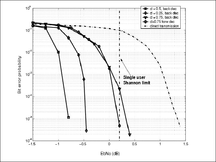

u u Binary input Gaussian relay channel Power allocation between source/relay d=0. 25 1 Rate = 1/2, N = 2 x 10⁴, B = 40, d = 0. 25 0 10 0. 9 -1 Bit Error Probability 0. 8 Rate 0. 7 0. 6 0. 5 0. 4 0. 3 0. 1 -5 -4 -3 -2 -1 0 Eb/Nomin (d. B) 1 2 3 -2 10 -3 10 -4 10 -5 Lower Bound Decode and Forward Single User System 0. 2 10 10 4 -6 10 -4 -3. 5 Eb /N 0 (d. B) -3 -2. 5

Research Platforms: Theory to Practice u Implementation – Simulation environment – Research hardware platform
")
Research Platform--TAPs u Wireless Transit Access Points (TAP)

Research Platform--TAPs u u TAP to TAP link – 4 X 4 static channel with line of sight – Channel state information at Rx and Tx n Spatial waterfilling n OFDM with spectral waterfilling – Target: 20 bits per second per Hz MU to TAP/TAP to MU – 802. 11 compatible – Relay

Funding u u Government – The National Science Foundation – State of Texas Industry – Texas Instruments – Nokia – Intel – Xilinx – National Instruments

Conclusions u u u MIMO performance with single antenna at terminal Network channel model – Relay – User cooperation n Routing n Scheduling All IP n Protocol Backbone n Coding Building prototypes
- Slides: 38