
Cooling the ET payloads Fulvio Ricci Talk outline
- Slides: 31
Cooling the ET payloads Fulvio Ricci
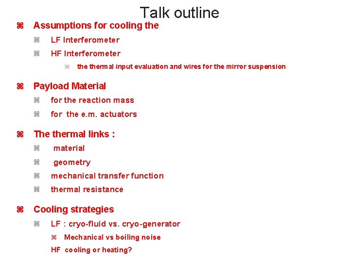
Talk outline Assumptions for cooling the LF Interferometer HF Interferometer thermal input evaluation and wires for the mirror suspension Payload Material for the reaction mass for the e. m. actuators The thermal links : material geometry mechanical transfer function thermal resistance Cooling strategies LF : cryo-fluid vs. cryo-generator Mechanical vs boiling noise HF cooling or heating?
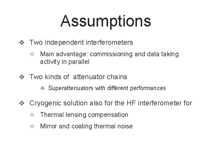
Assumptions v Two independent interferometers v Main advantage: commissioning and data taking activity in parallel v Two kinds of attenuator chains v Superattenuators with different performances v Cryogenic solution also for the HF interferometer for v Thermal lensing compensation v Mirror and coating thermal noise
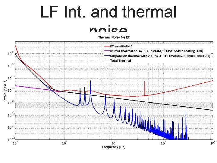
LF Int. and thermal noise
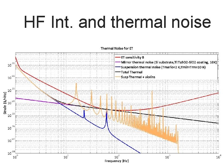
HF Int. and thermal noise
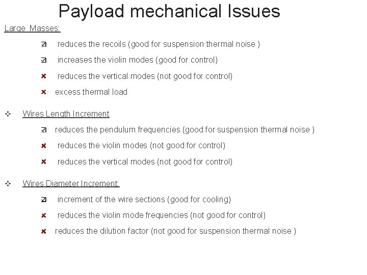
Payload mechanical Issues Large Masses: reduces the recoils (good for suspension thermal noise ) increases the violin modes (good for control) reduces the vertical modes (not good for control) excess thermal load v Wires Length Increment reduces the pendulum frequencies (good for suspension thermal noise ) reduces the violin modes (not good for control) reduces the vertical modes (not good for control) v Wires Diameter Increment: increment of the wire sections (good for cooling) reduces the violin mode frequencies (not good for control) reduces the dilution factor (not good for suspension thermal noise )
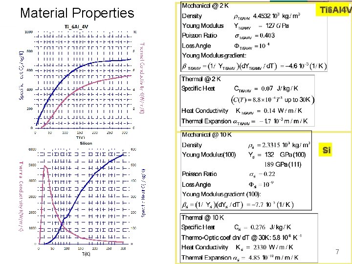
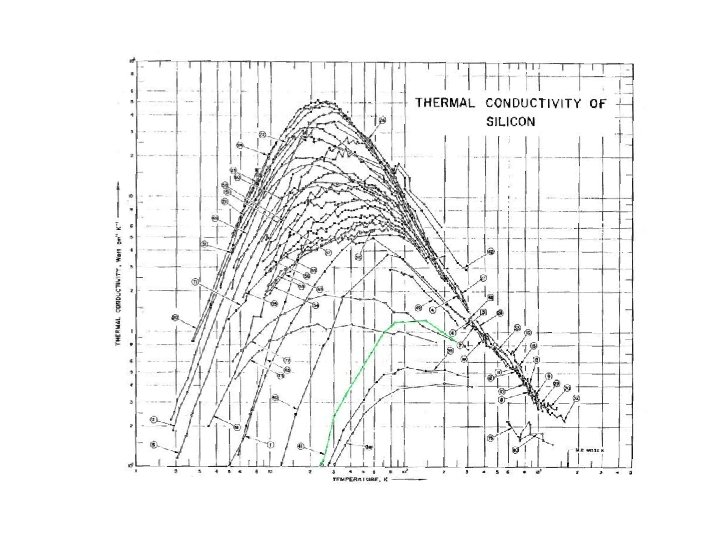
Material Properties Ti 6 Al 4 V Si 7
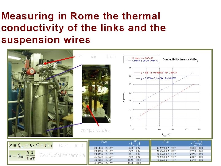
Measuring in Rome thermal conductivity of the links and the suspension wires PT Cryomech multistage sample Cu. Be 3 Potenza immessa Conducibilità termica
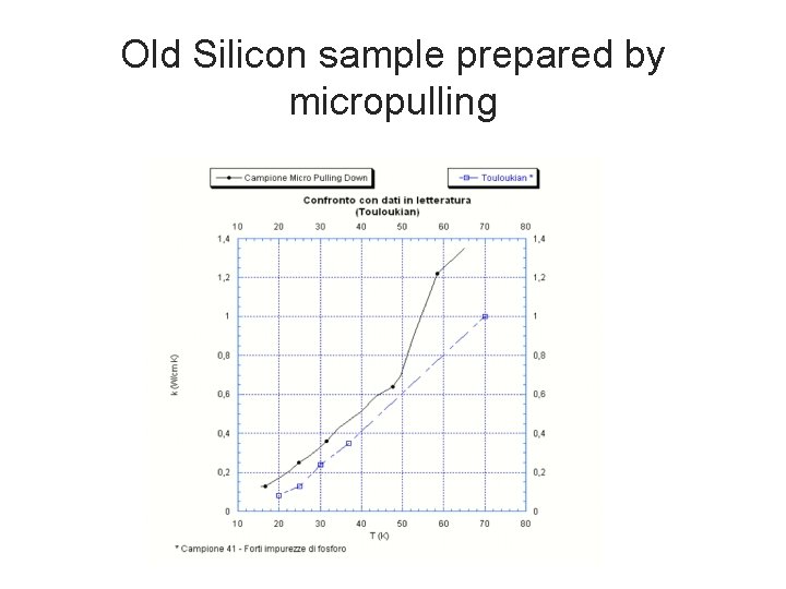
Old Silicon sample prepared by micropulling
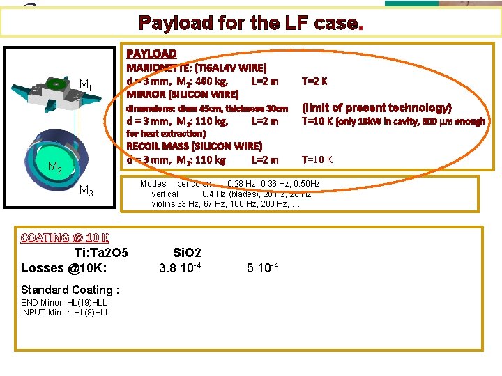
Payload for the LF case. PAYLOAD M 1 MARIONETTE: (TI 6 AL 4 V WIRE) d = 3 mm, M 1: 400 kg, L=2 m MIRROR (SILICON WIRE) dimensions: diam 45 cm, thickness 30 cm d = 3 mm, M 2: 110 kg, for heat extraction) L=2 m RECOIL MASS (SILICON WIRE) d = 3 mm, M 3: 110 kg L=2 m M 2 M 3 COATING @ 10 K Ti: Ta 2 O 5 Losses @10 K: Standard Coating : END Mirror: HL(19)HLL INPUT Mirror: HL(8)HLL T=2 K (limit of present technology) T=10 K (only 18 k. W in cavity, 600 mm enough T=10 K Modes: pendulum 0. 28 Hz, 0. 36 Hz, 0. 50 Hz vertical 0. 4 Hz (blades), 20 Hz, 26 Hz violins 33 Hz, 67 Hz, 100 Hz, 200 Hz, … Si. O 2 3. 8 10 -4 5 10 -4
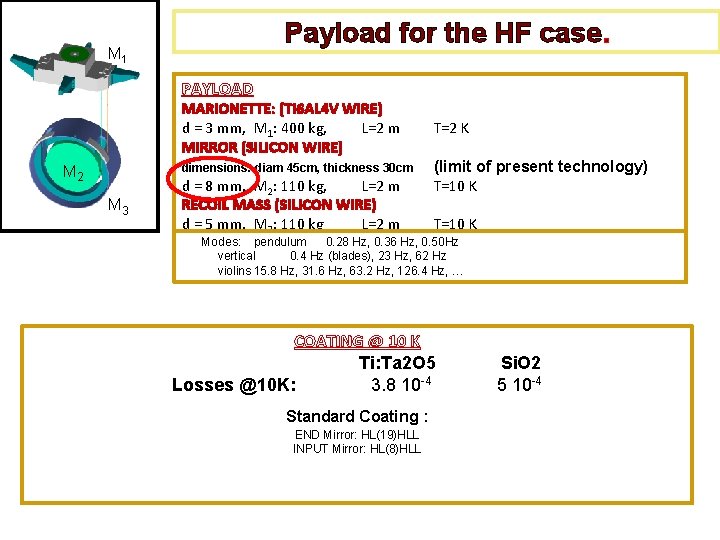
Payload for the HF case. M 1 PAYLOAD MARIONETTE: (TI 6 AL 4 V WIRE) d = 3 mm, M 1: 400 kg, L=2 m MIRROR (SILICON WIRE) dimensions: diam 45 cm, thickness 30 cm M 2 M 3 d = 8 mm, M 2: 110 kg, L=2 m RECOIL MASS (SILICON WIRE) d = 5 mm, M 3: 110 kg L=2 m T=2 K (limit of present technology) T=10 K Modes: pendulum 0. 28 Hz, 0. 36 Hz, 0. 50 Hz vertical 0. 4 Hz (blades), 23 Hz, 62 Hz violins 15. 8 Hz, 31. 6 Hz, 63. 2 Hz, 126. 4 Hz, … COATING @ 10 K Ti: Ta 2 O 5 Losses @10 K: 3. 8 10 -4 Standard Coating : END Mirror: HL(19)HLL INPUT Mirror: HL(8)HLL Si. O 2 5 10 -4
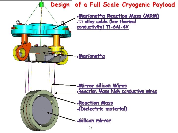
Design of a Full Scale Cryogenic Payload 13
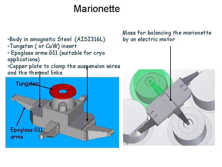
Marionette • Body in amagnetic Steel (AISI 316 L) • Tungsten ( or Cu. W) insert • Epoglass arms G 11 (suitable for cryo applications) • Copper plate to clamp the suspension wires and thermal links Tungsten Epoglass G 11 arms Mass for balancing the marionette by an electric motor
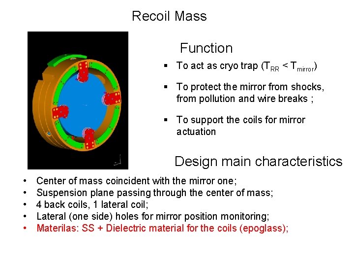
Recoil Mass Function § To act as cryo trap (TRR < Tmirror) § To protect the mirror from shocks, from pollution and wire breaks ; § To support the coils for mirror actuation Design main characteristics • • • Center of mass coincident with the mirror one; Suspension plane passing through the center of mass; 4 back coils, 1 lateral coil; Lateral (one side) holes for mirror position monitoring; Materilas: SS + Dielectric material for the coils (epoglass);
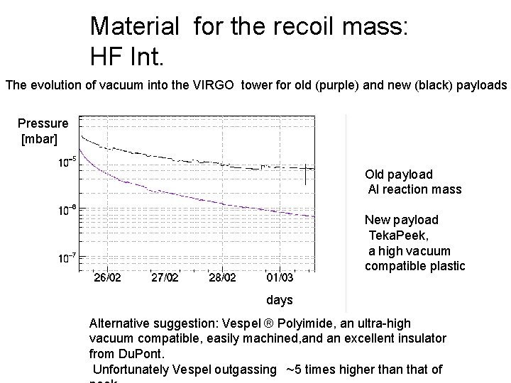
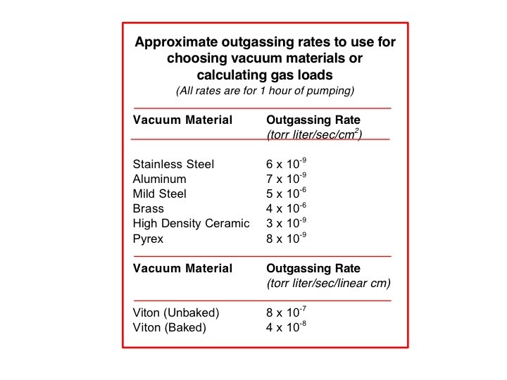
Material for the recoil mass: HF Int. The evolution of vacuum into the VIRGO tower for old (purple) and new (black) payloads Pressure [mbar] Old payload Al reaction mass New payload Teka. Peek, a high vacuum compatible plastic days Alternative suggestion: Vespel ® Polyimide, an ultra-high vacuum compatible, easily machined, and an excellent insulator from Du. Pont. Unfortunately Vespel outgassing ~5 times higher than that of
Approximate outgassing rates to use for choosing vacuum materials or calculating gas loads (All rates are for 1 hour of pumping) Vacuum Material Stainless Steel Aluminum Mild Steel Brass. High Density Ceramic Pyrex Vacuum Material Viton (Unbaked) Viton (Baked) Outgassing Rate(torr liter/sec/cm 2)6 x 10⁹ 7 x 10 -9 5 x 10 -6 4 x 10 -6 3 x 10 -9 8 x 10⁹ Outgassing Rate(torr liter/sec/linear cm)8 x 10 -7 4 x 10 -8
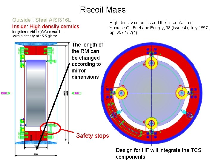
Recoil Mass Outside : Steel AISI 316 L Inside: High density cermics tungsten carbide (WC) ceramics with a density of 15. 5 g/cm 3 High-density ceramics and their manufacture Yamase O. : Fuel and Energy, 38 (issue 4), July 1997 , pp. 257 -257(1) The length of the RM can be changed according to mirror dimensions Safety stops Design for HF will integrate the TCS 18 components
Electromagnetic actuators Same kind of Coil - Magnet System used in Virgo: Nb-Ti wires embedded in a copper matrix Coil and Magnet Size can be changed according to constraints given by locking. Electrostatic actuators easily adapted 3/11/2008 Piero Rapagnani 19
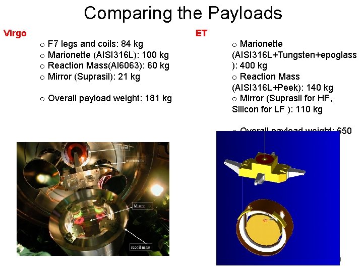
Comparing the Payloads Virgo ET o F 7 legs and coils: 84 kg o Marionette (AISI 316 L): 100 kg o Reaction Mass(Al 6063): 60 kg o Mirror (Suprasil): 21 kg o Overall payload weight: 181 kg o Marionette (AISI 316 L+Tungsten+epoglass ): 400 kg o Reaction Mass (AISI 316 L+Peek): 140 kg o Mirror (Suprasil for HF, Silicon for LF ): 110 kg o Overall payload weight: 650 kg 20
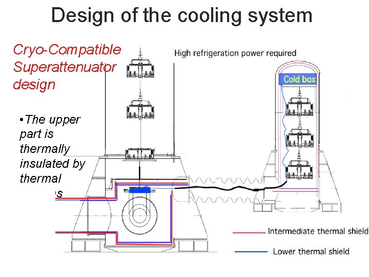
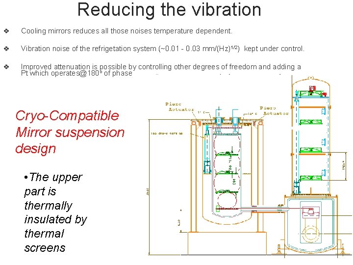
Design of the cooling system Cryo-Compatible Superattenuator design Tanks to R. Passaquieti • The upper part is thermally insulated by thermal screens 3 21
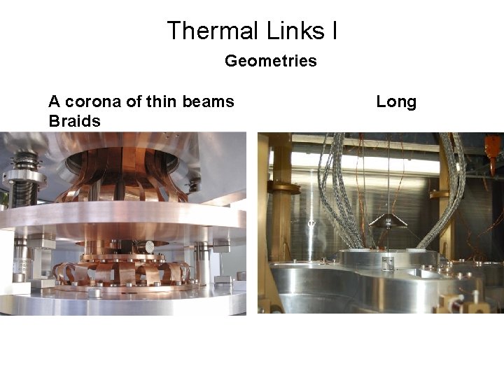
Thermal Links I Geometries A corona of thin beams Braids Long
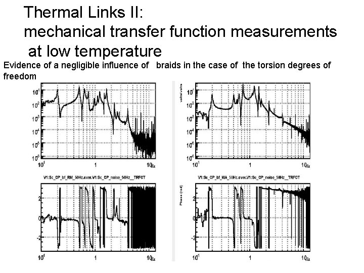
Thermal Links II: mechanical transfer function measurements at low temperature Evidence of a negligible influence of braids in the case of the torsion degrees of freedom
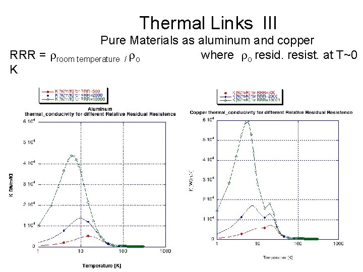
Thermal Links III Pure Materials as aluminum and copper RRR = rroom temperature / ro where ro resid. resist. at T~0 K
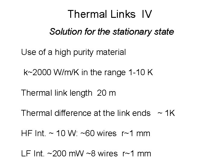
Thermal Links IV Solution for the stationary state Use of a high purity material k~2000 W/m/K in the range 1 -10 K Thermal link length 20 m Thermal difference at the link ends ~ 1 K HF Int. ~ 10 W: ~60 wires r~1 mm LF Int. ~200 m. W ~8 wires r~1 mm
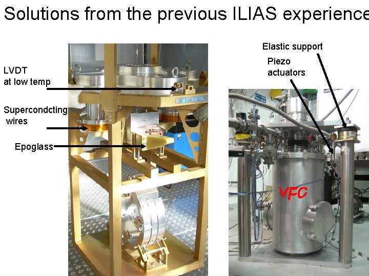
Solutions from the previous ILIAS experience Elastic support LVDT at low temp Supercondcting wires Epoglass Piezo actuators
Reducing the vibration v Cooling mirrors reduces all those noises temperature dependent. v Vibration noise of the refrigetation system (~0. 01 - 0. 03 mm/(Hz)1/2) kept under control. v Improved attenuation is possible by controlling other degrees of freedom and adding a Pt which operates@180 o of phase Cryo-Compatible Mirror suspension design • The upper part is thermally insulated by thermal screens 27
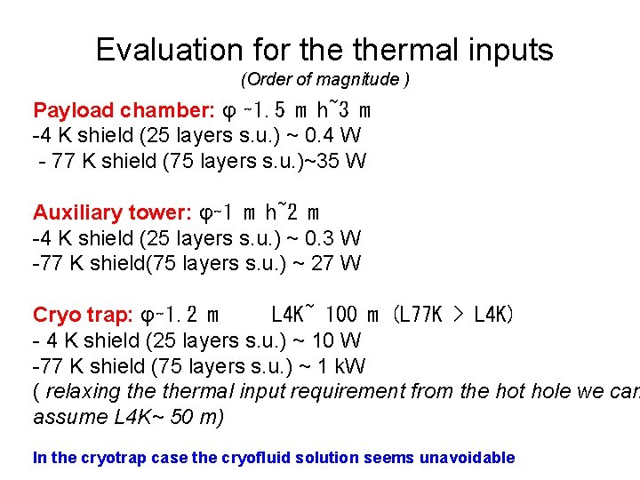
Evaluation for thermal inputs (Order of magnitude ) Payload chamber: φ ∼ 1. 5 m h~3 m -4 K shield (25 layers s. u. ) ~ 0. 4 W - 77 K shield (75 layers s. u. )~35 W Auxiliary tower: φ∼ 1 m h~2 m -4 K shield (25 layers s. u. ) ~ 0. 3 W -77 K shield(75 layers s. u. ) ~ 27 W Cryo trap: φ∼ 1. 2 m L 4 K~ 100 m (L 77 K > L 4 K) - 4 K shield (25 layers s. u. ) ~ 10 W -77 K shield (75 layers s. u. ) ~ 1 k. W ( relaxing thermal input requirement from the hot hole we can assume L 4 K~ 50 m) In the cryotrap case the cryofluid solution seems unavoidable
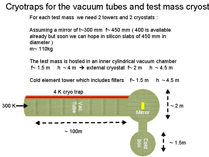
Cryotraps for the vacuum tubes and test mass cryost For each test mass we need 2 towers and 2 cryostats : Assuming a mirror of t~300 mm f~ 450 mm ( 400 is available already but soon we can hope in silicon slabs of 450 mm in diameter ) m~ 110 kg The test mass is hosted in an inner cylindrical vacuum chamber f~ 1. 5 m h ~ 4 m external cryostat f~ 2 m h ~ 4. 5 m Cold element tower which includes filters f~ 1. 5 m h ~ 4. 5 m 4 K cryo trap Vac. Tube 300 K ~2 m Mirror ~ 100 m Cold box ~ 1. 5 m
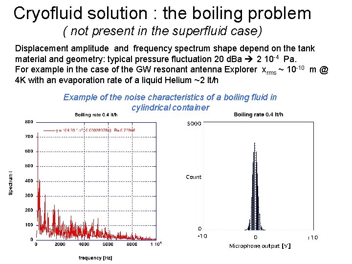
Cryofluid solution : the boiling problem ( not present in the superfluid case) Displacement amplitude and frequency spectrum shape depend on the tank material and geometry: typical pressure fluctuation 20 d. Ba 2 10 -4 Pa. For example in the case of the GW resonant antenna Explorer xrms ~ 10 -10 m @ 4 K with an evaporation rate of a liquid Helium ~2 lt/h Example of the noise characteristics of a boiling fluid in cylindrical container
Open points for the discussion Do we agree to assume still that HF is a cryo detector? -If yes, the operating temperature is defined mainly by the optimization of the heat extraction from the mirror ( max thermal conductivity) -If not, we have to review thermal noise contribution on the ET-HF sensitivity curve The cooling time - We need to reduce it ( up to 1 week per mirror ) - use of the He gas exchange, a complex solution in a real GW interferometer - Use a telescopic system to transmit the refr. power via