Conversion Processes Cracking Cracking is the breakdown of

Conversion Processes: Cracking

Cracking is the breakdown of heavy hydrocarbon molecules into lighter ones. Cracking can be done Catalytically and/or Thermally. • Catalytic Cracking: catalyzed by the presence of defined catalyst. Examples of catalytic cracking are fluidized-bed catalytic cracking (FCC) and hydrocracking • Thermal Cracking: Catalyzed by heat. Examples of thermal cracking processes are visbreaking and solvent deasphalting • In this Chapter, the focus will be on Catalytic Cracking.

Fluidized Catalytic Cracking Convert heavy hydrocarbon fractions from vacuum distillation into a lighter mixture of more useful products Feedstock undergoes a chemical breakdown, under controlled heat (450 – 500 o. C) and pressure, in the presence of a catalyst Fluidized Catalytic Cracking Effective catalyst: small pellets of silica, alumina or magnesia and nowadays zeolite.

Fluidized Catalytic Cracking: Products • Primary goals: - To make gasoline & diesel - To minimize the production of heavy fuel oil - To produce large amounts of olefins, which are used as » Feedstocks for petrochemical industry » Production of butylene, propylene & ethylene » C 5+ olefins can be alkylated to produce high-octane gasoline

Fluidized Catalytic Cracking REACTOR Catalytic cracking is the most important and widely used refinery process for converting heavy oils into more valuable gasoline and lighter products (e. g. LPG). REGENERATOR RISER The cracking process also produces carbon (coke) which remains on the catalyst particle and rapidly lowers its activity. To maintain the catalyst activity at a useful level, it is necessary to regenerate the catalyst by burning off this coke with air. q As a result, the catalyst is continuously moved from reactor to regenerator and back to reactor. q The cracking reaction is endothermic and the regeneration reaction exothermic.

Chemistry of Catalytic Cracking The “Cracking” reaction is a composite of many reactions 1. Initiation --- making the carbenium ion 2. Isomerization --- manipulating the carbenium ion 3. ß-scission --- cutting the carbenium ion into two 4. Hydrogen ion transfer --- the engine that keeps things going 5. Termination --- removing the carbenium ion as an olefin

Initiation 1. Production of olefin through mild thermal cracking of paraffins, then these olefins attract a proton from the catalyst to form carbenium ions. 2.

Isomerization - Stabilizing Carbenium Ions

Cracking: cutting C-C bond

Hydrogen Ion Transfer The carbenium ions propagate the chain reaction by transferring a hydrogen ion from a n-paraffin to form a paraffin molecule and a new carbenium ion. Thus another carbenium ion is formed and the chain is ready to repeat itself.

Termination

Fluidized Catalytic Cracking Catalyst q The FCC process employs a catalyst in the form of very fine particles [average particle size about 70 micrometers (microns)] which behave as a fluid when aerated with a vapor (and this is why it is called fluidized catalytic cracking). The fluidized catalyst is circulated continuously between the reaction zone and the regeneration zone and acts as a vehicle to transfer heat from the regenerator to the oil feed and reactor. REACTOR REGENERATOR RISER

Fluidized Catalytic Cracking To Fractionator q The hot oil feed is contacted with the catalyst in he feed riser line and/or the reactor. q As the cracking reaction progresses, the catalyst is progressively deactivated by the formation of coke on the surface of the catalyst. q The catalyst and hydrocarbon vapors are separated mechanically, and oil remaining on the catalyst is removed by steam stripping before the catalyst enters the regenerator. q The oil vapors are taken overhead to a fractionation tower for separation into streams having the desired boiling ranges. REACTOR REGENERATOR RISER Hot oil air

Fluidized Catalytic Cracking q The spent catalyst flows into the regenerator and is reactivated by burning off the coke deposits with air. To Fractionator Flue gases REACTOR REGENERATOR q Regenerator temperatures are carefully controlled to prevent catalyst deactivation by overheating. RISER Hot oil air q This is done by controlling the air flow to give a desired CO 2/CO ratio in the exit flue gases or the desired temperature in the regenerator. q The flue gas and catalyst are separated by cyclone separators and electrostatic precipitators.

Fluidized Catalytic cracking q Two basic types of FCC units in use today are the ‘‘side-by-side’’ type, where the reactor and regenerator are separate vessels adjacent to each other, and the stacked type, where the reactor is mounted on top of the regenerator. side-by-side FCC units stacked type FCC units

FCC Process The ratio of catalyst: oil = 4: 1 to 9: 1 by weight. Residence time of the gas < 5 seconds REGENERATOR FCC feed is preheated to 650 o. F and is fed into the riser Which contains hot catalyst from the regenerator The vapor generated by the cracking process lifts the catalyst up the riser. The vapor velocity at the base of the riser REACTOR is about 6 m/s and increases to over 20 m/s at the riser exit. RISER

A spent catalyst is withdrawn from the bottom of reactors and stripped with steam to vaporize the hydrocarbons remaining on the surface Stripping removes most of the hydrocarbon vapors which are entrained between the particles of catalyst FCC Process REACTOR REGENERATOR It is desirable to separate the vapor and catalyst as quickly as possible RISER to prevent overcracking of the desired products.
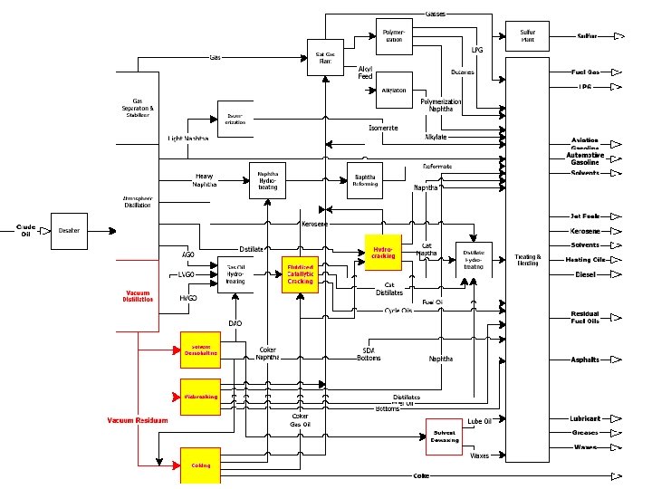
 Flowsheet")
Fluidized Catalytic Cracking (FCC) Flowsheet
- Slides: 19