Conventional Eddycurrent NDE Exciter Receiver Electronics Exciter Receiver


 Gradiometer Reference SQUID Sensor A A-B Sensor t signal to be")


 =0,")

 diff–z relations at x = 0 for various f Phase-depth")


 for various conductor specimens")


- Slides: 29
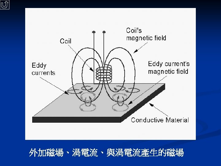
Conventional Eddy-current NDE Exciter / Receiver Electronics Exciter / Receiver Coil Magnetic core Scan Conducting specimen Phase shifts Discontinuity 1. The eddy current in the specimen is induced by the excitation coil and the electronics. Excitation field ~ m. T Defect signal ~ T 2. The magnetic field generated by the eddy current is then detected by the receiver coil and the electronics.
Disadvantage of conventional eddycurrent NDE • Poor resolution at low frequencies Not suitable for detecting deep flaws. • Large in sensor size Limits the spatial resolution; Interaction between the sensor and specimen is not negligible.
High-sensitivity Eddy-current NDE Electronics Gradiometer Excitation Coil Scan Defect signal Conducting specimen Discontinuity Excitation field ~ T Excitation field ~ m. T Defect signal ~ n. T Conventional Defect signal ~ T
Merits of SQUID-based Eddy-current NDE • High sensitivity in sensing low frequency magnetic fields higher than 1 p. T in an unshielded environment • Large dynamic range at low frequency from T to p. T • Small size of the pick-up coil (< 1 cm x 1 cm) We can have better spatial resolution. • Frequency independent transfer function d. V/d. B.
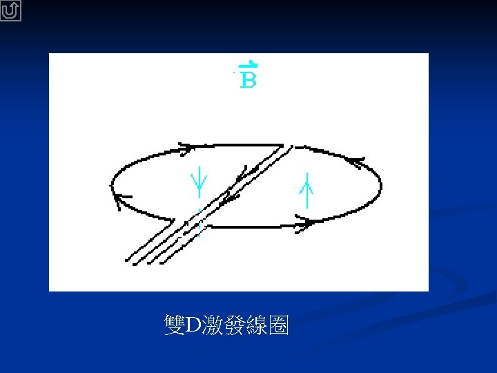
• Design of three NDE Systems Single Magnetometer Axial Electronic Gradiometer µ-metal shield Planar Gradiometer Reference sensor Signal-shift compensation Sensing Sensor X Z Double-D excitation coil X X Z Double-D excitation coil Z Circular excitation coil
Quantitative NDE
NDE System with a single magnetometer eddy-current probe Output Electronics Signal Generator Imbalance Compensation Clock Signal Generator Shielded Magnetometer Lock-in Amplifier Reference An additional signal generator for signal-shift compensation is required. Data Acquisition Excitation Sample Computer RS-232 X-Y stage Stepping motor controller
NDE System with an axial electronic gradiometer eddy-current probe Electronics A-B Gradiometer output With Electronics B Axial Gradiometer Signal Generator Lock-in Amplifier Reference A two-channel electronics and one difference electronics. Data Acquisition Excitation Sample Computer RS-232 X-Y stage X-Y Stepping motor controller
B Electronic (Axial) Gradiometer Reference SQUID Sensor A A-B Sensor t signal to be detected
NDE system with a planar gradiometer Eddy-Current Probe Electronics Gradiometer output With a singlechannel electronics Signal Generator Planar Gradiometer Circular excitation coil Sample Lock-in Amplifier Reference Data Acquisition Excitation Computer RS-232 X-Y stage X-Y Stepping motor controller
Integrated Planar Gradiometer A-B Loop A signal to be detected Integrated Gradiometer is more stable, but Electronic Gradiometer is usually more sensitive.
• Depth analysis for hidden cracks Usually , NDE only detects the existence of the crack. Here we try to locate the depth of the cracks.
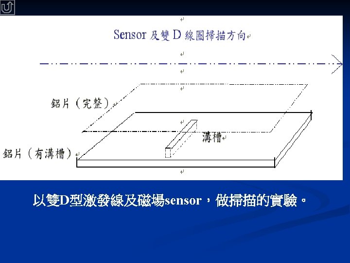
Experimental Test of Defect Signals single magnetometer / double-D excitation coil X Scan Aluminum p Artificial f la late w
shift There are shifts in Bi and Bq. shift Shifts can be removed after taking the differentiation. d. Bq dx Flaw center Bdiff d. Bi dx
Differential Defect Signal & Differential Phase in which Differential Defect Signal If V(0) =0, Namely, Phase Differential Phase *H. -E Horng and J. -T Jeng et al. , Physica C 367, 303 -307 (2002)
We first found that the differential method can be applied to the NDE technique.
diff /dz (mm) diff–z relations at x = 0 for various f Phase-depth relation is approximately linear. For example, at 400 Hz : diff flaw depth z = 0. 037× ( diff +47º) z (mm)
diff–z relations for various flaw sizes 240 Flaw height 240 2. 0 mm 1. 5 mm 1. 0 mm 180 diff (º) 300 120 2. 0 mm 1. 5 mm 0. 7 mm 120 60 ƒ =400 Hz 0 -60 0 Flaw width 2 4 6 z (mm) 8 10 60 ƒ =400 Hz 0 -60 0 2 4 6 z (mm) 8 10 diff –z relation remains the same if flaw size < skin depth* * For aluminum, skin depth = 4 mm at ƒ = 400 Hz
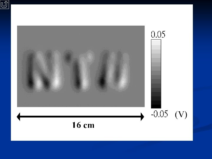
Depth analysis of hidden cracks with differential methods f = 400 Hz NDE system scan crack 2 crack 1
f = 400 Hz , 1. 0 cm excitation coil diff The spatial resolution of the system is limited to the size of the excitation coil.
Universal curve of d diff /dz vs. (skin depth) for various conductor specimens
Conclusion and Outlook We have demonstrated quantitatively with the high. TC SQUID NDE. We first found that the differential method can be applied to the NDE technique. The depth of the flaw can be determined quantitatively. Planar gradiometer is promising for NDE system, because it : is more stable in an unshielded environment