
Controls Infrastructure Timo Korhonen ICS Chief Engineer www
- Slides: 16
Controls Infrastructure Timo Korhonen ICS Chief Engineer www. europeanspallationsource. se
Overview • • Control system infrastructure components MTCA base infrastructure Timing system Machine Protection System Digital platforms, status and support Procurement and Installation Interface with Beam Instrumentation Summary 2
Control system infrastructure components • MTCA. 4 – Crates, MCH, Cooling Units, PSU – Platform Management – Crate variants: 12 -slot and 6 -slot • I/O and processing – Digital platforms • Network and servers – Network hardware in-kind contribution from Norway • Timing System – EVG, EVR, Distribution System 3
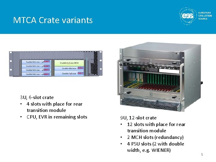
MTCA base infrastructure • Crates in two variants • 12 -slot, 9 U crate – For (LL)RF systems that can utilize many slots – Has been in use, stable configuration • 6 -slot, 3 U crate – For smaller, more distributed systems (saves rack space) – Backplane issues • Vendors consider MTCA backplanes as “custom” • Defined an “ESS-specific” backplane – follows layout of the bigger crate – Cooling and airflow issues with prototype • Added one fan to improve airflow • Front-to-rear cooling is challenging due to small air inlet area • MCH (Micro Channel Hub) standardized on N. A. T. • Power supplies need final definition – Wiener has good noise performance but issues with size 4
MTCA Crate variants 3 U, 6 -slot crate • 4 slots with place for rear transition module • CPU, EVR in remaining slots 9 U, 12 -slot crate • 12 slots with place for rear transition module • 2 MCH slots (redundancy) • 4 PSU slots (2 with double width, e. g. WIENER) 5
Timing system • MRF Event System – Components defined – Uses latest design with active delay compensation • Higher frame rate possible • Unlimited fan-out depth • Etc. – MTCA. 4 version with backplane trigger and clock support • Software support to be finalized • Details of interfacing to BI (and other) systems to be discussed and finalized – A preliminary, incomplete definition exists (ESS-0088633) 6
Machine Protection System • Interfacing to MPS – System concept is ready and accepted – Detail discussions are still underway • Interface defined, consisting of – Discrete lines • OK/NOK, disconnect (“ 3 -wire”) • For fast switch-off – Ethernet link (UDP) • Operating mode checking, heartbeat, online testing • Removes dependency on timing system direct link for mode data transfer – PDR recommendation was to investigate this issue 7
Digital platforms, status and support • Struck SIS 8300 -L 2, KU – Supported until final platform (IFC 1420) at equivalent or better performance level • The agreement as I have understood it. • We assume that this system is essentially ready (no substantial development resources needed. ) – MPS (BIS) interface issues to be clarified • ESS-designed interface cannot be used (no compatible outputs) • “collect” signals from different connectors (Harlink, RTM, SFP) • Firmware interface (programming resources to be found) – Procurement etc. is BI responsibility 8
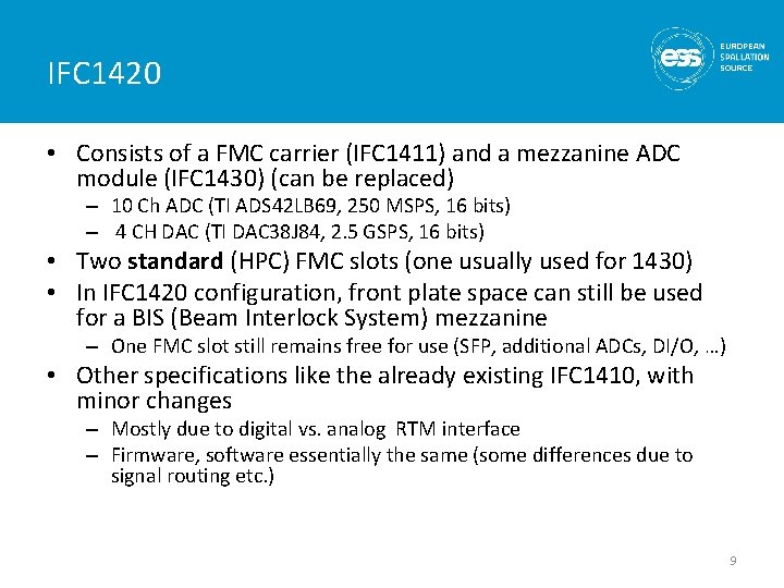
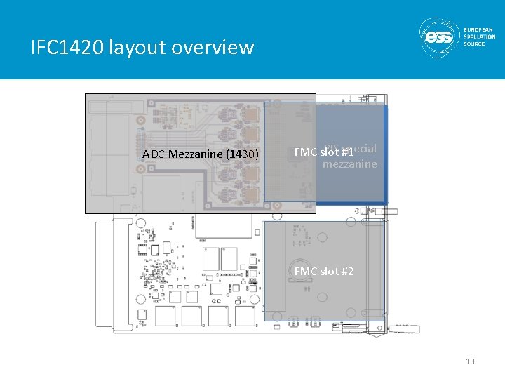
IFC 1420 • Consists of a FMC carrier (IFC 1411) and a mezzanine ADC module (IFC 1430) (can be replaced) – 10 Ch ADC (TI ADS 42 LB 69, 250 MSPS, 16 bits) – 4 CH DAC (TI DAC 38 J 84, 2. 5 GSPS, 16 bits) • Two standard (HPC) FMC slots (one usually used for 1430) • In IFC 1420 configuration, front plate space can still be used for a BIS (Beam Interlock System) mezzanine – One FMC slot still remains free for use (SFP, additional ADCs, DI/O, …) • Other specifications like the already existing IFC 1410, with minor changes – Mostly due to digital vs. analog RTM interface – Firmware, software essentially the same (some differences due to signal routing etc. ) 9
IFC 1420 layout overview ADC Mezzanine (1430) BIS #1 special FMC slot mezzanine FMC slot #2 10
Digital platforms, status and support • IFC 1420 – Delays due to slow start of in-kind • And ramp-up of internal resources • On the other hand, too early design would have meant rework. – CDR on Wednesday (May 23), prototype production scheduled for June • Unless major obstacles show up in CDR – Strong support from PSI (in-kind) • • 1 FPGA engineer, 1 SW engineer full time, 2 more will be employed Part-time support of 7 more people (controls, LLRF, instrumentation) Use of PSI resources for analog characterization (in progress) Frees up internal staff for integration tasks – Hardware also contributed in-kind 11
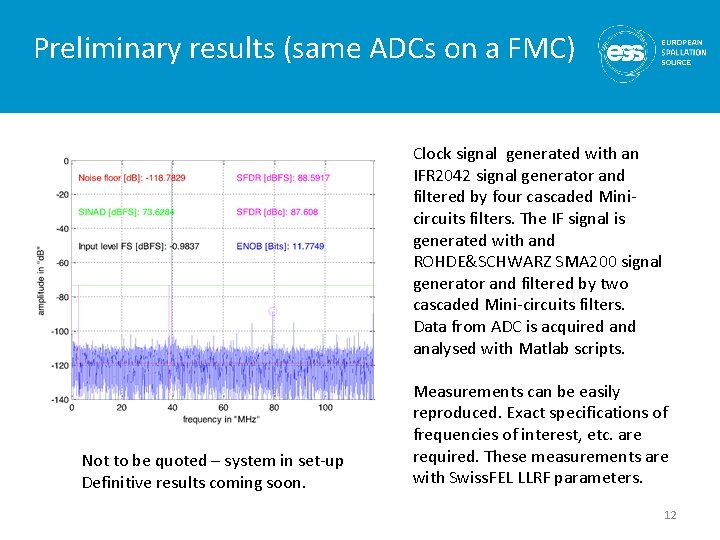
Preliminary results (same ADCs on a FMC) Clock signal generated with an IFR 2042 signal generator and filtered by four cascaded Minicircuits filters. The IF signal is generated with and ROHDE&SCHWARZ SMA 200 signal generator and filtered by two cascaded Mini-circuits filters. Data from ADC is acquired analysed with Matlab scripts. Not to be quoted – system in set-up Definitive results coming soon. Measurements can be easily reproduced. Exact specifications of frequencies of interest, etc. are required. These measurements are with Swiss. FEL LLRF parameters. 12
Networks and servers • Network design done – – Technical (aka controls) network backbone State-of-the-art performance level Hardware in-kind contribution from Norway Installation, cabling is underway • System-level connection details to be defined • Some EPICS IOCs already running on site – CF systems with PLCs • Temporary control room being equipped – As well as server infrastructure (also temporary until server room ready) 13
Procurement and Installation • 3 U Crate expected in June (new backplane, “custom”) – No agreed “standard backplane” by the manufacturers (according to our discussions) • 9 U crate technically ready • Need to go through a tendering process (3 U and 9 U) – Resulting in a framework agreement – Final delivery timetable to be defined • Timing system components procurement in progress – Backbone cabling design done, detail distribution TBD • IFC 1420 from in-kind partner as soon as FAR (final Article Review) done + procurement time – Need to decide how many and when 14
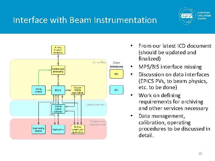
Interface with Beam Instrumentation • From our latest ICD document (should be updated and finalized) • MPS/BIS interface missing • Discussion on data interfaces (EPICS PVs, to beam physics, etc. to be done) • Work on defining requirements for archiving and other services necessary • Data management, calibration, operating procedures to be discussed in detail. 15
Summary • MTCA base infrastructure defined – Work still required to verify performance and functionality • Timing system components defined – Procurement process in preparation • Platform support defined – Details still to be finalized – Final platform development speeding up after a slow start • Control system services defined but more details to be discussed – Interface document should be finalized 16