
Control Testbed Student Ezra Idy Professor Vikram Kapila
Control Testbed Student: Ezra Idy Professor: Vikram Kapila
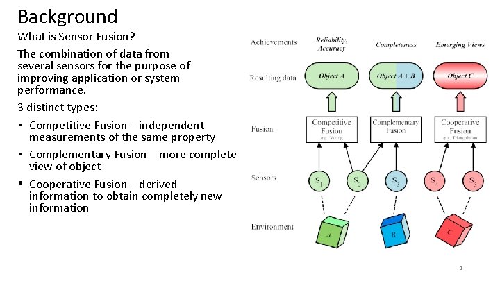
Background What is Sensor Fusion? The combination of data from several sensors for the purpose of improving application or system performance. 3 distinct types: • Competitive Fusion – independent measurements of the same property • Complementary Fusion – more complete view of object • Cooperative Fusion – derived information to obtain completely new information 2
Objective • Create an easy, affordable, and accessible Sensor Fusion system • Analyze the data obtained from: • Individual sensors • Multiple sensors 3
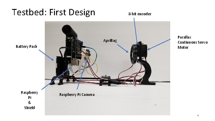
Testbed: First Design 8 -bit encoder Apriltag Battery Pack Raspberry Pi & Shield Parallax Continuous Servo Motor Raspberry Pi Camera 4
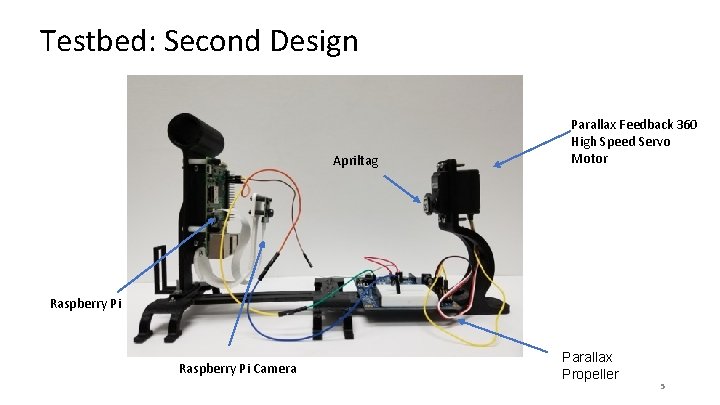
Testbed: Second Design Apriltag Parallax Feedback 360 High Speed Servo Motor Raspberry Pi Camera Parallax Propeller 5
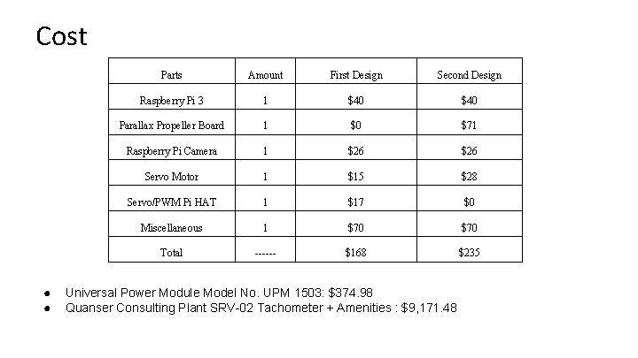
Cost ● ● Parts Amount First Design Second Design Raspberry Pi 3 1 $40 Parallax Propeller Board 1 $0 $71 Raspberry Pi Camera 1 $26 Servo Motor 1 $15 $28 Servo/PWM Pi HAT 1 $17 $0 Miscellaneous 1 $70 Total ------ $168 $235 Universal Power Module Model No. UPM 1503: $374. 98 Quanser Consulting Plant SRV-02 Tachometer + Amenities : $9, 171. 48
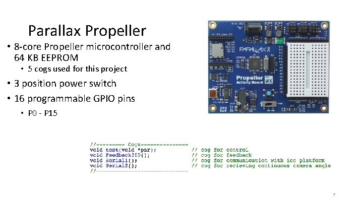
Parallax Propeller • 8 -core Propeller microcontroller and 64 KB EEPROM • 5 cogs used for this project • 3 position power switch • 16 programmable GPIO pins • P 0 - P 15 7
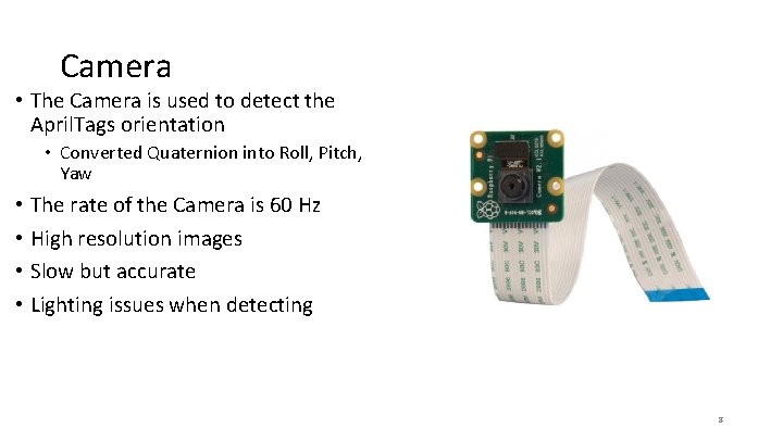
Camera • The Camera is used to detect the April. Tags orientation • Converted Quaternion into Roll, Pitch, Yaw • The rate of the Camera is 60 Hz • High resolution images • Slow but accurate • Lighting issues when detecting 8
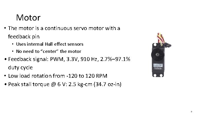
Motor • The motor is a continuous servo motor with a feedback pin • Uses internal Hall effect sensors • No need to “center” the motor • Feedback signal: PWM, 3. 3 V, 910 Hz, 2. 7%– 97. 1% duty cycle • Low load rotation from -120 to 120 RPM • Peak stall torque @ 6 V: 2. 5 kg-cm (34. 7 oz-in) 9
Application • Educational purpose – Can be used to teach sensor fusion on a basic level • Interactive learning – Learn Kalman Filtering and PID control • Embedded vs remote – Learn about the different sensor types and how they affect a system 10
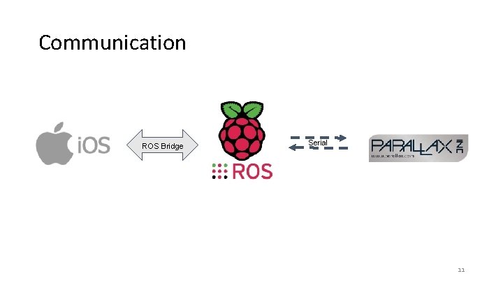
Communication ROS Bridge Serial 11
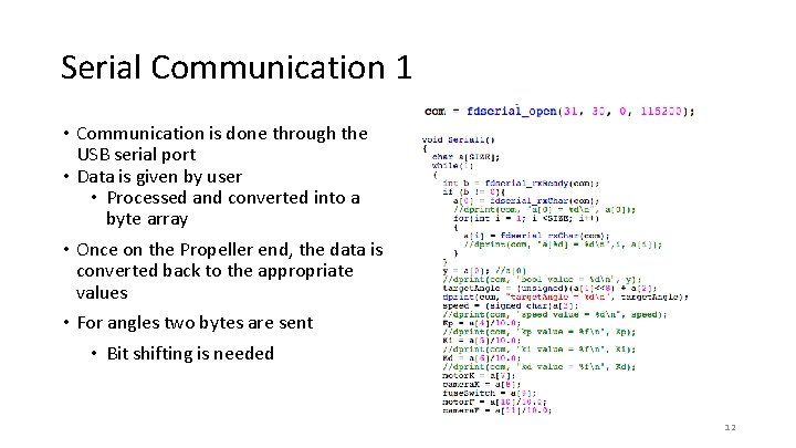
Serial Communication 1 • Communication is done through the USB serial port • Data is given by user • Processed and converted into a byte array • Once on the Propeller end, the data is converted back to the appropriate values • For angles two bytes are sent • Bit shifting is needed 12
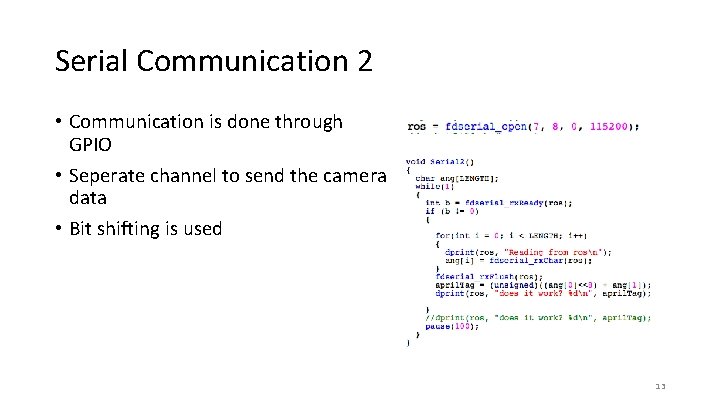
Serial Communication 2 • Communication is done through GPIO • Seperate channel to send the camera data • Bit shifting is used 13
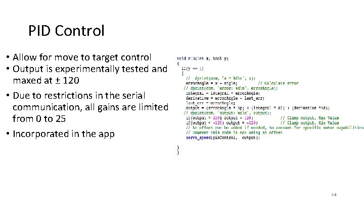
PID Control • Allow for move to target control • Output is experimentally tested and maxed at ± 120 • Due to restrictions in the serial communication, all gains are limited from 0 to 25 • Incorporated in the app 14
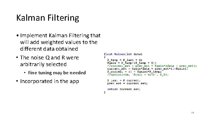
Kalman Filtering • Implement Kalman Filtering that will add weighted values to the different data obtained • The noise Q and R were arbitrarily selected • Fine tuning may be needed • Incorporated in the app 15
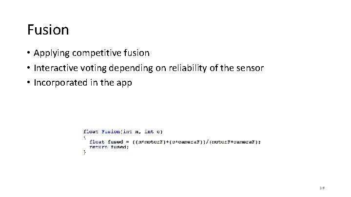
Fusion • Applying competitive fusion • Interactive voting depending on reliability of the sensor • Incorporated in the app 16
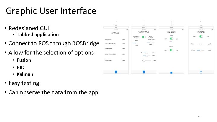
Graphic User Interface • Redesigned GUI • Tabbed application • Connect to ROS through ROSBridge • Allow for the selection of options: • Fusion • PID • Kalman • Easy testing • Can observe the data from the app 17

Future Work • Take a video 18
Entrepreneurship • Project was chosen for the Stern Entrepreneurship collaboration • The Stern students are currently validating customers • Testing the educational marketplace • In contact with CIJE (Center for Initiatives in Jewish Education) • In contact with ITEST 19
- Slides: 19