Control system of RIKEN RI Beam Factory Nishina

Control system of RIKEN RI Beam Factory Nishina Center / RIKEN Misaki KOMIYAMA (misaki@riken. jp) 12/Mar/2008, EPICS collaboration meeting in Shanghai

谢谢你给予说的机会 Thank you very much for giving me an opportunity to introduce you our facility.

Contents • Brief introduction of RIKEN • Brief introduction of Nishina Center for accelerator-based science and its accelerators (RIBF) • Introduction of RIBF control system • Introduction of RIBF beam interlock system
")
What is the RIKEN? -1 • Institute of Physical and Chemical Research ( 理化学研究所) • Main campus : in Wako city, Saitama Pref. • 7 institutes in Japan (ex. SPring-8) • 3 overseas branches (at BNL, MIT, RAL). • First organized in 1917 as a private research foundation, and reorganized in 2003 as an independent administrative institution under the Ministry of Education, Culture, Sports, Science and Technology.

What is RIKEN? -2 • Carries out high level experimental and research work in a wide range of fields, including physics, chemistry, medical science, biology, and engineering, covering the entire range from basic research to practical application. • Personnel (As of Apr. 1 2007) : 3441 (140 in Nishina Center) • Budget (fiscal year 2007) : about 90 BJYen (~80 MUS$) • President : Dr. Ryoji NOYORI
 Center for Accelerator-Based Science • Inaugurated")
What is RIKEN Nishina Center? • Nishina (仁科) Center for Accelerator-Based Science • Inaugurated April 1, 2006 • Radioactive isotope (RI) beam facility : RI Beam Factory (RIBF) includes - variable-frequency linac (RILAC, 1980) - K 70 -Me. V AVF cyclotron (AVF, 1989) - K 540 -Me. V ring cyclotron (RRC, 1986) - K 570 -Me. V fixed frequency ring cyclotron (f. RC) - K 980 -Me. V intermediate stage ring cyclotron (IRC) - K 2600 -Me. V superconducting ring cyclotron (SRC) - superconducting fragment separator (Big. RIPS)
, RIKEN Nishina Center, Wako-city Old Facility: 1975 ~ 1990 16")
RI Beam Factory (RIBF), RIKEN Nishina Center, Wako-city Old Facility: 1975 ~ 1990 16 BJYen RIBF: 1997 ~ (2012) 50 BJYen
 RRC RILAC RIPS f. RC Big. RIPS IRC SRC")
Layout of RIBF (in 2007) RRC RILAC RIPS f. RC Big. RIPS IRC SRC
 (world’s first) K = 2, 600 Me. V Self Magnetic")
Superconducting Ring Cyclotron (SRC) (world’s first) K = 2, 600 Me. V Self Magnetic Shield Self Radiation Shield 3. 8 T (240 MJ) 18 -38 MHz 8, 300 tons Cooled by liquid He bath Indirectly cooled by two phase forced He flow

K 2600 -Me. V SRC

Milestones of Commissioning -1 • At 16: 00 on December 28 2006, the first beam extracted from the SRC: a 345 Me. V/nucleon 27 Al 10+ beam was extracted. Its mass to charge ratio is the same as that of a 238 U 88+ beam. In this acceleration trial, we skipped the f. RC, because the vacuum leaking took place in this cyclotron. We could, however, confirm the acceleration performance of the SRC. • At 3: 00 on March 15 2007, the first RI beams were generated and identified by the Big. RIPS. A 345 Me. V/nucleon 86 Kr 31+ beam, mass to charge ratio of which is the same as that of a 238 U 86+ beam, was projectile-fragmented. In this test run, we succeeded in operating the full cyclotron cascade including f. RC for the first time. After the first beam run, we accelerated a uranium beam with the f. RC, and we observed that the most probable charge state after the stripping at 51 Me. V/nucleon is 86+ instead of 88+ originally expected.

Milestones of Commissioning -2 • At 21: 00 on March 23, we succeeded in the first acceleration of a 238 U 86+ beam up to 345 Me. V/nucleon. • And eventully, at 6: 40 on March 27, we successfully identified a large variety of RI beams produced via the first in-flight fission of the 345 Me. V/nucleon urnium beam. • At the first experiment of the RIBF in May using 345 Me. V/nucleon 238 U 86+ beam, we discovered a very-neutron-rich new isotope Pd 125 (N=79, Z=46).

Future Upgrades toward 1 pm. A • Intensity of SRC-extracted uranium beam obtained on June 29 2007 : 8. 2 en. A • Step-by-step improvements have been done; beam diagnostic devices, charge stripper foil, … • Under construction of new injector to RRC, with 28 GHz SC-ECRIS

Outline of RIBF Control System -1 • Control system : based on EPICS R 3. 14. 7 / R 3. 14. 4 on Linux • 4 EPICS Servers and 20 IOCs • Ion Source exit ~ RRC exit : - Based on CAMAC and CIM/DIM (RIKEN original intelligent controller for CAMAC system) - CAMAC loop -> Ethernet using network-based CAMAC crate controller (CC/NET, product of Toyo corp. ) - replace them with NIO/N-DIM/PLC step by step • RRC exit ~ Big. RIPS target : - Based on NIO (for magnet power supply, product of NDS) / N -DIM (Network-based DIM, RIKEN original intelligent controller, for beam diagnostic devices and vacuum) / PLC (for beam diagnostic devices and vacuum and so on)

N-DIM • • • Network-based intelligent Controller Each N-DIM has one IP Address 32 -bit DI/DO and 12 Channels of 16 -bit AI Control commands are written in ASCII code Radiation-resistance Device N-DIM FC : control 3 Faraday cups N-DIM PF : control 1 beam profile monitor N-DIM VAC : control 2 sets of vacuum system N-DIM BIAS : control 4 bias power supplies for FC N-DIM RP : control 1 beam differential probe Price : 1500 US$ (board), 1000 US$ (case)

CC/NET, CIM, DIM, N-DIM

Outline of RIBF Control System -2 • Independent from Beam Interlock system (based on PLC), only monitoring • Using MEDM / Channel. Archiver / Alarm. Handler / Zlog (KEK) • Group member : 1 + 1 (beam operator)

RIBF Control Room
 : RIKEN original")
Interface Devices for RIBF control • • DIM (Device Interface Module) : RIKEN original module / intelligent controller / 32 bit-DI/DO, 16 * 12 bit AI / radiation-resistance N-DIM (Network-DIM) : RIKEN original module / network-based intelligent controller / 32 bit-DI/DO, 12 * 16 bit AI / radiation-resistance NIO : product of NDS Control system of Ion source, RF : stand-alone

Number of devices and controller in RIBF
 • 1 Cisco’s Catalyst 4506 device")
Control Network • Stand-alone (no connection with office-network) • 1 Cisco’s Catalyst 4506 device as a router, 9 Catalyst 2950 devices as edge switches, set up optical fiber cables among them. • Designed to have 5 subnetworks : 1. for VME (control magnet power supplies), server computer, PCs 2. for N-DIM (monitor beam current, vacuum) 3. for N-DIM (monitor beam profile), server computer 4. for PLC (control beam diagnostic devices, etc. ) 5. for maintenance the network system itself


Structure of RIBF Control System
 • • WRAP (Wireless Router Application Platform, http: //www. pcengines.")
EPICS IOC box (Linux) • • WRAP (Wireless Router Application Platform, http: //www. pcengines. ch/) Disk less and Fan less (CF boot) Embedded Linux with LFS (Linux From Scratch) - Linux kernel 2. 6. 13 - GRUB - glibc - Busy. Box - Apache - bash - telnet daemon - NTP - PHP - EPICS base R 3. 14. 7 ~US$150 / WRAP 9 WRAP in RIBF Each WRAP mounts EPICS programs from a server computer, and share Details : A. Uchiyama et al. , “Development of embedded system for running EPICS IOC by using Linux and single board computer” in Proc. of ICALEPCS 07
 • Stop beam within 10 msec. at the exit of")
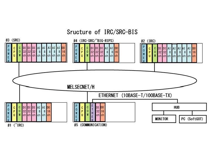
Beam Interlock System (BIS) • Stop beam within 10 msec. at the exit of Ion Source after receiving safety alarms from accelerators and equipments on beam transport lines. • Based on Melsec PLC • 3 BIS in RIBF (for RILAC / for RRC-f. RC / for IRC-SRC) • Input signals : - magnet power supply error - vacuum error (GV) - radiation safety - RF - beam intensity (FC / BF) • Total signals : ~400 / BIS (DI / AI, except RILAC)

Next work in progress • Arrange a connection point between Control-LAN and Office-LAN • Introduce a Relational Database System to control system to keep every beam parameter from EPICS system / non. EPICS system

感�清听! Thank you for your attention!
- Slides: 28