Continuous Model Synthesis Paul Merrell and Dinesh Manocha


, divide the plane into")
 to become empty – It")

 many arches are synthesized (right). The")


- Slides: 35
Continuous Model Synthesis Paul Merrell and Dinesh Manocha In SIGGRAPH Asia 2008 발표: 이성호
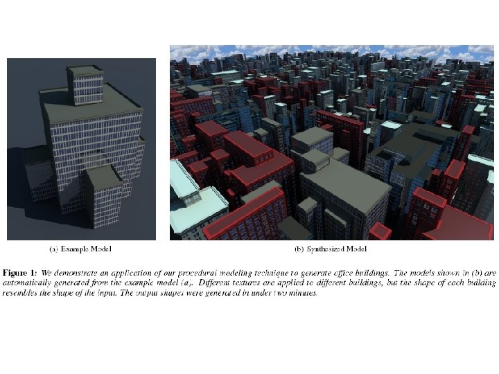
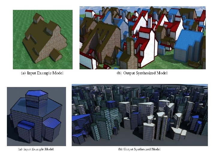
Abstract • Input: 3 D polyhedral model – Exploits the connectivity • between the adjacent boundary features of the input model • Output: – A model that has similar connected features • and resembles the input • Algorithm proceeds automatically • Our algorithm – Is simple to implement – Can generate a variety of complex shapes
Introduction • Automatically modeling complex shapes – 3 D CAD and modeling tools • limited in terms of generating complex models • can be cumbersome to use • Procedural modeling techniques – shape grammars, scripting languages, Lsystems, fractals, or solid texturing • limited to a specific class of models • require considerable user input or guidance
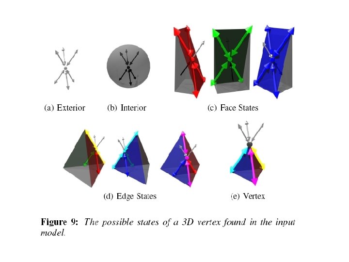
Approach • Enumerates multiple configurations of – each vertex, edge, and face – discards any configurations • that do not satisfy the constraints • Runtime performance – depends on • the number of distinct normal directions of the input faces
Benefits • Simplicity – Simple to use – Proceeds automatically • Generality – Can generate a wide variety of complex shapes • Architectural buildings, landscapes, terrains and fractal shapes • Efficiency – Generates complex shapes in only a few minutes
Related work L-systems • Prusinkievicz et al. 2001
Fractals • Musgrave et al. 1989
Split grammars • Wonka et al. 2003
Creating truss structures • Smith et al. 2002
Cellular texturing • Legakis 2001
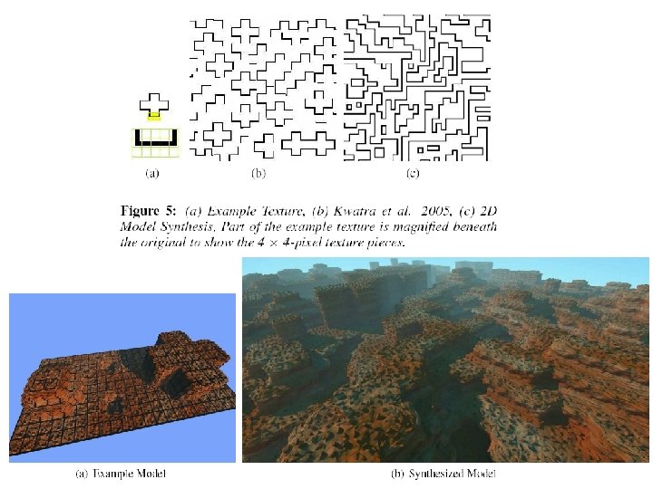
Texture synthesis • Efros and Leung 1999; Wei and Levoy 2000; Efros and Freeman 2001; Kwatra et al. 2003 – What a sophisticated! • Doretto et al. 2003; Kwatra et al. 2003 – Time-varying textures • Kopf et al. 2007 – 3 D solid textures
Model synthesis • Merrell 2007
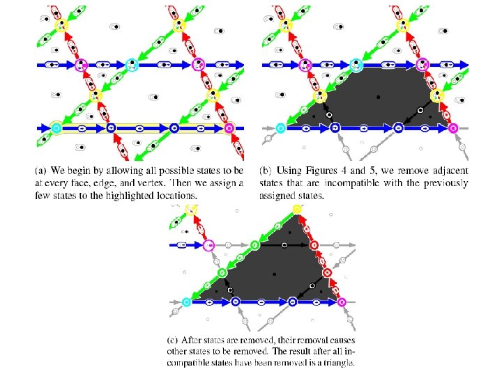
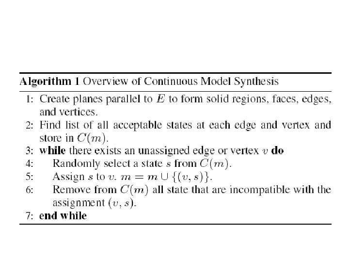
Algorithm
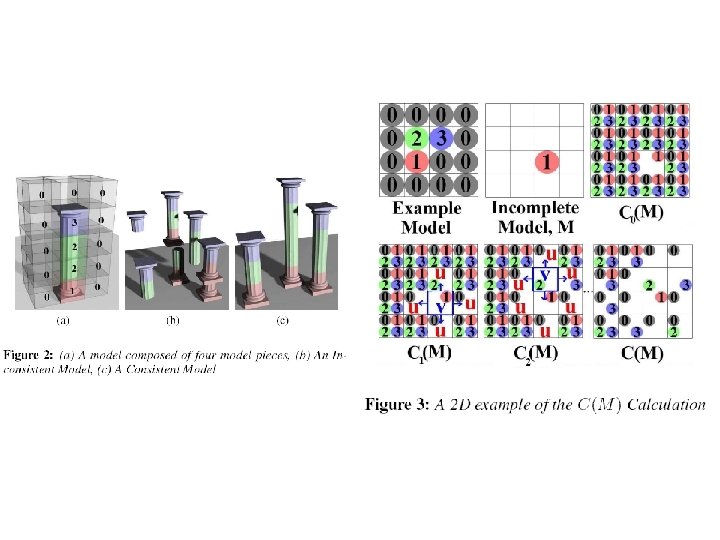
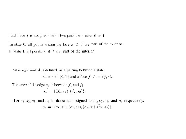
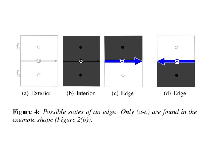
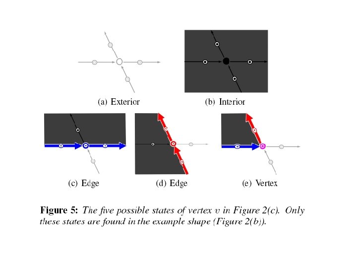
Adjacency Constraint
Finding valid states Lines parallel to the input shape (a), divide the plane into faces, edges, and vertices (c). The output shape (d) is formed within the parallel lines. The set of acceptable vertex and edges states in the output (d) can be found by dividing the input along parallel lines (b).
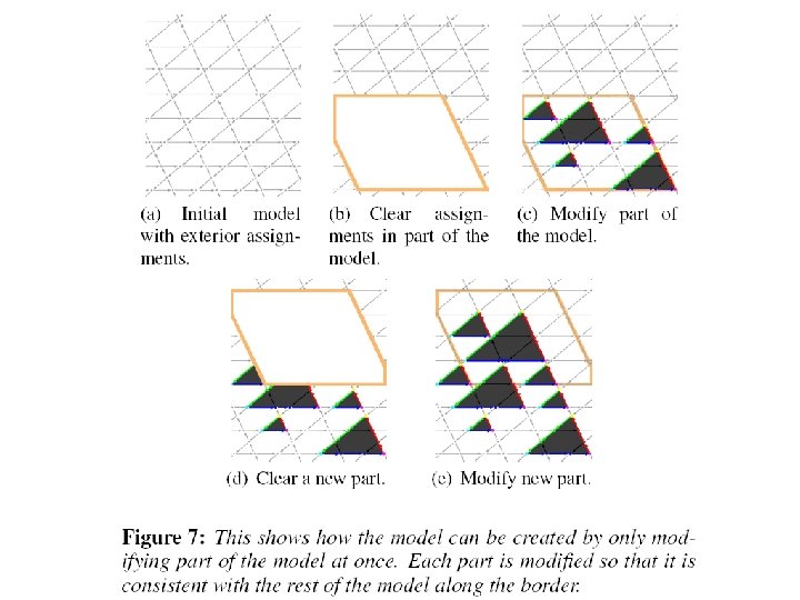
Backtracking issue • Incorrect assignment – possible assignments C(m) to become empty – It must backtrack – Modify small parts of the space • as shown in Figure 7 • Modifying volume of 10 x 10 or smaller – our algorithm almost always succeeds • A solution can always be found
Generating 3 D models
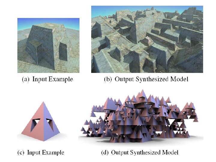
Figure 11: From the input example model (left) many arches are synthesized (right). The output contains interesting new variations not found in the input such as structures with multiple arches and arches passing over arches (insets).
Synthesis time
Analysis and comparison • Shape grammars – [Muller et al. 2006, Wonka et al. 2003] – user must specific – and adjust many production rules • Our approach – user only needs to specify an input model
Limitations • time and memory requirements – If m parallel planes are generated – for each of n distinct normals, – O(n 3 m 3) vertices • Difficult to generate objects at different scales – Creating many architectural details • Unable to control – could be improved by imposing additional constraints • The size and distribution of the objects – An object must have a particular width or height
Conclusion and future work • Automatically modeling large complex shapes – Resemble simple models provided by the user • The input model need not be axis aligned • Not handled properly – More than three faces intersecting at a vertex – Constrain some objects • To be a fixed discrete size