Continuous Electron Beam Accelerator Facility Polarized eSource Talking

Continuous Electron Beam Accelerator Facility Polarized e-Source - Talking Points for PV experiments: P. Adderley, M. Bastani. Nejad, J. Clark, S. Covert, J. Hansknecht, J. Grames, R. Mammei, Matt Poelker, M. Stutzman, R. Suleiman, K. Surles-Law

Continuous Electron Beam Accelerator Facility A parity factory…. Beam energy 0. 4 - 6 Ge. V Current ~ n. A to 180 u. A Polarization ~ 85% 0. 6 Ge. V linac (20 cryomodules) 1497 MHz 67 Me. V injector (2 1/4 cryomodules) 1497 MHz Gain switched diode lasers 499 MHz, Df = 120 A B RF separators 499 MHz C B A Pockels cell Gun C A HAPPEx PVDIS PREx Moller G 0 Qweak B C Double sided septum

Worth Talking About… • Accelerator parity tools • Properly aligned pockels cell • Charge/position feedback techniques • Spin flip schemes: line or non-line locked, pairs/quartets/octets, etc • Two-Wien spin flipper • Fast pockels cell switch • The photogun and its properties • Helicity control board • Helicity magnets for active position feedback • Proper grounding techniques • Beam envelope matching for optimum adiabatic damping • What makes each experiment difficult? • G 0: low repetition rate, very high bunch charge • Qweak: high current (photogun lifetime, minimizing beam scraping) • Moller: duration, tightest proposed beam quality specs: charge, position and angle, synchrotron radiation at high energy might introduce beam noise • Global questions • How to detect small helicity pickup without requiring months of beam? • Hall beamline configuration, too many constraints (Hall A) • Accelerator staff: getting them to appreciate the nature of beam requirements • Finding that one person to manage all the details…. . • At what point can’t we do a proposed PV experiment?

Worth Talking About… • Accelerator parity tools • Properly aligned pockels cell • Charge/position feedback techniques • Spin flip schemes: line or non-line locked, pairs/quartets/octets, etc • Two-Wien spin flipper • Fast pockels cell switch • The photogun and its properties • Helicity control board • Helicity magnets for active position feedback • Proper grounding techniques • Beam envelope matching for optimum adiabatic damping • What makes each experiment difficult? • G 0: low repetition rate, very high bunch charge • Qweak: high current (photogun lifetime, minimizing beam scraping) • Moller: duration, tightest proposed beam quality specs: charge, position and angle, synchrotron radiation at high energy might introduce beam noise • Global questions • How to detect small helicity pickup without requiring months of beam? • Hall beamline configuration, too many constraints (Hall A) • Accelerator staff: getting them to appreciate the nature of beam requirements • Finding that one person to manage all the details…. . • At what point can’t we do a proposed PV experiment?
 I (µA) Target Apv (ppb)")
Parity Experiments Requirements can’t measure Experiment Energy (Ge. V) I (µA) Target Apv (ppb) Maximum Charge Asym (ppb) Maximum Position Diff (nm) Maximum Angle Diff (nrad) Maximum Size Diff (δσ/σ) HAPPEx-II (Achieved) 3. 0 55 1 H 1400 1 0. 2 Was not specified HAPPEx-III (Achieved) 3. 484 100 1 H 16900 200± 100 3± 3 0. 5± 0. 1 10 -3 PREx 1. 056 100 208 Pb 500± 15 100± 10 2± 1 0. 3± 0. 1 10 -4 QWeak 1. 162 180 1 H 234± 5 100± 10 2± 1 30± 3 10 -4 Møller 11. 0 85 1 H 35. 6± 0. 74 10± 10 0. 5± 0. 5 0. 05± 0. 05 10 -4 (20 cm) (25 cm) (0. 5 mm) (35 cm) (150 cm)

Two Wien Filters: Slow Helicity Reversal for PREx and Qweak o Insertable Half Wave Plate (IHWP), used for years: slow helicity reversal of laser polarization I. Identify false asymmetries II. Cancel out some helicity correlated systematic effects, but not all… o New: Slow helicity reversal of electron polarization using two Wien Filters and solenoid: III. Cancel out another class of helicity-correlated beam asymmetries from the source including spot size IV. Solenoid rotates spin by +/- 90° (spin rotates as B, but focus as B 2) Ø Maintain constant Injector and Accelerator configuration (that’s the goal) V. Today’s design can be used up to maximum voltage of 140 k. V

Wien Filter Spin Manipulator Equal but opposite E and B forces, rotate the spin and leave trajectory constant

Electron Polarization Slow Reversal “Spin Flipper” Vertical Wien = 90 deg Two Solenoids = ± 90 deg “Longitudinal Polarization” Horizontal Wien = {-90 … +90} From Gun FLIP - LEFT FLIP - RIGHT Joe Grames, Kent Paschke, Reza Kazimi

Two-Wien Spin Flipper • flip spin each week to cancel out HC laser spot variation • Baked beamline for good vacuum • Good for beams up to 140 k. V • Some steering required. Users complain beam quality not optimized after wards (Compton bkgd) • One mistake: Prebuncher should have been moved downstream of 2 nd Wien.

Fast Helicity Reversal o We have been using 30 Hz helicity reversal for years: Ø Ø o Power line 60 Hz frequency is major source of noise in parity experiments For 30 Hz reversal, T_Stable (= 33. 333 ms) contains exactly two cycles of 60 Hz line noise → this reversal cancels line noise Problem: Ø target density fluctuations, occurring faster than 30 Hz o Solution: Flip helicity faster, but need a better pockels cell switch o 60 Hz beam motion a nuisance….

Initial attempts and problems encountered This approach needed big capacitors…. lots of current Two commercial highspeed / high-voltage transistor (~$8000) Exaggeration of voltage droop on cell and subsequent re-charge after a helicity flip. Droop causes a serious problem when helicity flip rate was changed from a toggle to a pseudo-random pattern: pockels cell “memory” high-voltage switch (~$10, 000) All-in-one commercial bipolar Charge droop was greatly improved, but high speed ringing of the cell was a problem for the settling time. In addition, the large highspeed switching currents created a noise induced helicity pickup on sensitive helicity DAQ components. Work of John Hansknecht

Solution: Opto-diode Encapsulated Opto-diode $67 each • • • I = CΔV/ Charge time +/- quarter wave voltage = 5120 V Cell capacitance = 6 pf Desired charge time = 100 us Calculated current is only 307 u. A !! Work of John Hansknecht

New Opto Diode Pockels Cell Switch Push-Pull Circuit Pockels cell λ/2 flipping at 1 k. Hz. Perfect symmetry and no voltage droop over time. Pockels cell λ/2 transition optical result. ~70 us with no ringing. 1 2 3 The old switch was limited to 30 Hz helicity flip rates due to power handling limitations. Now we flip at 1 k. Hz for ~ 400$. Pockels cell “memory” not an issue anymore…. Work of John Hansknecht 4

Widths at 30 Hz and 1 k. Hz: For white noise, the increase in width going from 30 Hz to 1 k. Hz should be: 30 Hz, T_Stable = 33. 333 ms, T_Settle = 500 µs 1 k. Hz, T_Stable = 0. 980 ms, T_Settle = 60 µs But we don’t have white noise. Mostly we have low frequency noise. So an unexpected benefit of flipping faster….

Qweak e-Source Issues • Provide high current, 180+ u. A, with very little beam loss • Option 1: Increase gun bias voltage • Modest increase from 100 k. V to 130 k. V • Why not higher? risk damaging gun due to field emission • Some injector magnets operating at max current right now • Option 2: Increase laser spot size • Qweak is a long experiment: how to maintain stability of front end with acceptable parity quality? • Injector drift, something charging up? • Minimize cycling gun HV ON/OFF • Coordinate Beam Studies, Spot Moves, and 2 -Wien Spin Flips

35 ps bunches from the gun prebuncher Emittance filter A 1 and A 2 (4 and 6 mm) Master slit sets bunchlength at buncher/capture section: 111 ps With our 100 k. V gun, lots of beam loss at front-end apertures when delivering 180 u. A: this introduces unwanted helicity correlated asymmetries, and wasted beam degrades photogun operating lifetime.

Benchmarking PARMELA Simulation Results Against Beam-Based Measurements at CEBAF/Jefferson Lab – work of Ashwini Jayaprakash, JLab PARMELA Simulation Results Measurements at CEBAF/JLab Bunchlength Vs Gun Voltage 250 200 150 115 k. V 100 k. V 50 85 k. V 0 70 k. V 0 50 100 150 Ave. Gun Current (u. A) 200 Transmission (%) Transmission vs Gun Voltage 100 90 80 70 60 50 40 30 20 10 0 50 100 150 Ave. Gun Current (u. A) 200 300 200 Ke. V 250 115 Ke. V 100 Ke. V 200 85 Ke. V 150 70 Ke. V 100 50 0 0 Similar Trends 115 k. V 100 k. V 85 k. V 70 k. V 0 Electron Bunchlength (ps) 300 Transmission (%) Electron Bunchlength (ps) Electron Bunchlength vs Gun Voltage 50 100 150 Ave. Gun Current (µA) 200 Transmission Vs Gun Voltage 100 90 80 70 60 50 40 30 20 10 0 200 Ke. V 115 Ke. V 100 Ke. V 85 Ke. V 70 Ke. V 0 50 100 150 Ave. Gun Current (µA) 200 Message: Beam quality, including transmission, improves at higher gun voltage

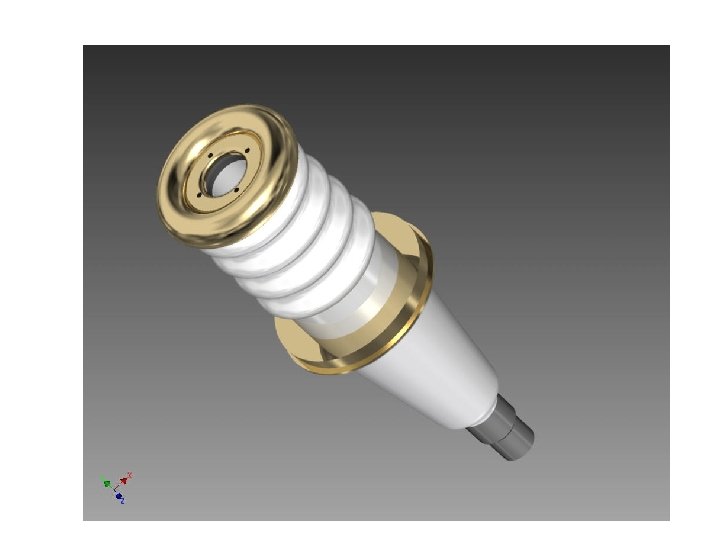
Old Gun Design We had low level field emission “Inverted” Gun Present Ceramic • Exposed to field emission • Large area • Expensive (~$50 k) • Lots of metal at HV e- Medical x-ray technology New Ceramic • Compact • ~$5 k • Less metal at HV • No SF 6 of N 2 New design Move away from “conventional” insulator used on most Ga. As photoguns today – expensive, months to build, prone to damage from field emission. High gradient locations not related to beam optics, lots of metal to polish

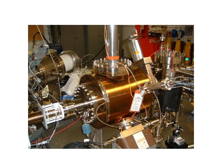
Paid for by ILC Inverted Gun #2 at Test Cave Large grain niobium electrode Problematic field emission at 140 k. V Repeated BCP treatment, no measurable field emission at 225 k. V • Have since demonstrated many months of beam delivery at 200 k. V • Our spare gun…… • • Inverted Gun #1 at CEBAF Operational since July, 2009 Stainless steel electrode Operated at 100 k. V for HAPPEx, PVDIS and PRex (70 C @ 150 u. A) • Operated at 130 k. V for Qweak (70 C @ 300 u. A), improved transmission • Expected better lifetime…. puzzling

4 m. A at High Polarization* Parameter Value Gun Bias Voltage 200 k. V Laser Rep Rate 1500 MHz Laser Pulselength 50 ps Wavelength 780 nm Laser Spot Size 350 mm Current 4 m. A Duration 1. 4 hr Charge 20 C Lifetime 80 C * Note: did not actually measure polarization QE Work of Riad Suleiman
")
Improve Lifetime with Larger Laser Spot? (Best Solution – Improve Vacuum, but not easy) Bigger laser spot, same # electrons, same # ions Ionized residual gas strikes photocathode Ion damage distributed over larger area

Lifetime with Large/Small Laser Spots Tough to measure large Coulomb lifetimes accurately with only 100 -200 C runs Observed factor of 5 to 10 improvement with larger laser spot size Expectation: 2 1550 ≈ 23 320 For Qweak Part 2, we can operate with 800 um laser spot instead of 500 um spot. Two benefits: • Enhance lifetime by ~ 2. 5 • Reduce space charge forces which should improve transmission (G 0 trick), maintain parity quality at 180+u. A Discrepancy explained in paper shown below

Møller Experiment • Max run avg charge asym 10 ppb. Transmission must be very high, 100% • Need position and angle feedback • No transverse polarization: how to measure? • Slow Helicity Reversal: • g-2 Spin Flip (change energy by 100 Me. V) • Two-Wien Flip • 2 k. Hz Fast Helicity Reversal and 10 µs Pockels Cell Settle • Beam Jitter: • Position Jitter/width < 10 µm • Charge Jitter/width < 300 ppm

Møller Experiment • 30 Weeks • Vertical/transverse polarization not measured at Hall. Feedback on vertical polarization? • How to measure HC pickup and ground loops on this new scale? • Compton spec, no accelerator diagnostic to tune to • 3? (competing? ) requirements at Hall: spot size at target, spot size at compton, phase advance and position of modulation coils, raster, etc. , • Synchrotron radiation might limit adiabatic damping, increase widths of HC measurements, and degrade polarization?

A New Injector for ~ 2015…. • 200 k. V polarized electron gun, upgraded 2 -Wien • An SRF capture section inside a… • New cryomodule that contains a single 7 -cell SRF cavity to make 10 Me. V beam • Replace one older full module with new C-100 to operate injector at 110 Me. V energy This helps us do PV experiments by… • Making a stiff beam out of gun, very little beamloss • Eliminate x/y coupling that hinders our ability to optimize position damping

Worth Talking About… • Accelerator parity tools • Properly aligned pockels cell • Charge/position feedback techniques • Spin flip schemes: line or non-line locked, pairs/quartets/octets, etc • Two-Wien spin flipper • Fast pockels cell switch • The photogun and its properties • Helicity control board • Helicity magnets for active position feedback • Proper grounding techniques • Beam envelope matching for optimum adiabatic damping • What makes each experiment difficult? • G 0: low repetition rate, very high bunch charge • Qweak: high current (photogun lifetime, minimizing beam scraping) • Moeller: duration, tightest proposed beam quality specs: charge, position and angle, synchrotron radiation at high energy might introduce beam noise • Global questions • How to detect small helicity pickup without requiring months of beam? • Hall beamline configuration, too many constraints (Hall A) • Accelerator staff: getting them to appreciate the nature of beam requirements • Finding that one person to manage all the details…. . • At what point can’t we do a proposed PV experiment?

Plan A Insulator sleeve Plan B No Improvement Plan D Plan C In hand, but untested Test this year

Why a Niobium Cathode Electrode? Work of Mazhad Bastani. Nejad

Krypton Processing High Voltage Electrodes Diamond Paste Polished SS Single Crystal Niobium and BCP Large Grain Niobium and BCP Work of Mazhad Bastani. Nejad

Injector Test Cave

Backup slides

o Summary of Fast Helicity Reversal Studies Ø Fast Helicity Reversal is needed: I. III. Huge reduction of noise from target density fluctuations Reduces noise on beam current by factor of 3 Reasonable reduction in beam position noise Ø T_Settle of 60 µs is very reasonable Ø Parity Experiment: Experiment Frequency Clock Pattern HAPPEx III & PVDIS 30 Hz Line-Locked Quartet PREx 240 Hz Line-Locked Octet QWeak 1 k. Hz Free Quartet Moller 2 k. Hz

Spin Flipper = Wien + Solenoid Long. Pol = Wien 4 Most Important Configurations Vertical Wien (MWF 1 I 04) Two Solenoids (MFG 1 I 04 A/B) Horizontal Wien (MWF 0 I 02) NO FLIP (old method) 0 deg +43 deg VERTICAL POL 90 deg +0 deg FLIP - LEFT 90 deg -47 deg FLIP - RIGHT 90 deg +90 deg -47 deg Some facts… Ø “Spin Flipping” is accomplished without changing Wien filters Ø Vertical Polarization is a “subset” of “Spin Flipper” operation Ø “Old Method” achieved by turning Vertical Wien off ØAbility to uniquely define spin in 4π

Want to move away from “conventional” insulator used on all Ga. As photo-guns today: expensive, months to build, prone to damage from field emission.

Other Developments • Charge Feedback: Ability to do Charge Feedback using either Pockels Cell or Intensity Attenuator without or with the option to correct for Pockels Cell hysteresis • Helicity Magnets: Ability to do Position Feedback using the newly commissioned helicity magnets located in the 5 Me. V region of the Injector • Pockels Cell Motion: Pockels Cell is equipped with remote controlled x & y translational stage for minimizing position differences while measuring the position differences of electron beam • Photocathode Rotation: With Load-Locked Gun, now we can zero the offset term in the charge asymmetry caused by the vacuum window birefringence by rotating the photocathode

Attenuator Rotatable Ga. As Photocathode IA Gain-switched Diode Laser and Fiber Amplifier LP HWP LP PC WP LP Shutter Helicity Control Board Helicity Flip Fiber 15° Dipole HV Supply (0 – 90 V) n. Helicity Flip Fiber Delayed Helicity Fiber Vacuum Window T-Settle Fiber Hall RHWP Charge Feedback (IA) Target V-Wien Filter Spin Solenoids DAQ BCM BPMs CEBAF Charge Feedback (PITA) Position Feedback H-Wien Filter HV Supply (0 – ± 4000 V) 5 Me. V Helicity Magnets PZT Mirror Pockels Cell IHWP Electron Beam

FLOATING VME CRATE Normal Grounded VME CRATE (slow status and control - nothing occurs at helicity flip rate) Helicity Control Board 16 bit DAC: Pockels Cell (PC) ±HV setpoints (0 – ± 4000 V) Helicity Flip Fiber 16 bit DAC: Hall A, B, C Intensity Attenuator (IA) HV setpoints RS-232: Rotating half-wave plate (RHWP) and laser attenuators IA 0 Fiber Discrete Digital I/O: Insertable half-wave plate (IHWP) IA 1 Fiber Injector Service Building Injector Tunnel Laser Hut Galvanic Analog/Digital Isolation Card PC +HV Supply Floating Analog/Digital I/O Optical Switch Control Fast High Voltage Switch PC -HV Supply IHWP RHWP & Attenuators IA HV Supply AC Power Source Floating DC Power To Floating Components Floating Circuit Common Halls IA’s Pockels Cell

Electronic Cross-talk & Ground Loop Elimination in Injector o VME Crate of Helicity Control Board is floating and powered with isolation transformer. o Helicity Board generates two real time helicity signals: Helicity Flip and n. Helicity Flip. Current drawn by board does not depend on helicity state. o Helicity signal is generated by pseudo-random bit generator. No correlation between helicity signal and any other signal in Accelerator or in Hall. o Outside world receives only Delayed Helicity signal. This signal tells what helicity was in the past so there is no knowledge of real time helicity. o Helicity Magnets VME Crate which receives one of the two real time helicity signals (n. Helicity Flip) is also floating and powered by isolation transformer. o Real time helicity signal (Helicity Flip) that goes to Laser Hut is isolated. All electronics that can see real time helicity are floating (next slide). o All helicity-correlated beam asymmetries (position, angle, charge, energy, and size – and thus beam scraping) are minimized so helicity is the only real time property of beam that is changing. o Programming of voltage setpoints of Pockels Cell and IA’s (both receive Helicity Flip signal) in Laser Hut passes through galvanic isolation card and there are no readbacks of these voltages.

Other Developments o o o Charge Feedback using either PITA or IA 4 -peak IA correction for Pockels Cell hysteresis (“memory”), although fast PC switch has significantly reduced this ill-effect Cleanup Insertable Linear Polarizer before the Pockels Cell is available during one Hall operation Pockels Cell is equipped with remote controlled x & y translational stage for minimizing position differences while measuring the position differences of electron beam. Pitch, roll and yaw adjustments could be added… With Load-Locked Gun, we can zero the offset term in the charge asymmetry caused by the vacuum window birefringence by rotating the photocathode

Our design has one region of “unintended” high gradient – could be problematic…. . exploring new designs via electrostatic modeling Work of Ken Surles-Law

Anode won’t always capture all FE…. Better to look for x-rays…. Building an inexpensive radiation monitoring system: lots of GM tubes, powered by one HV supply and data stream to computer via RS 232 Installation during 6 MSD Work of Riad Suleiman, Steve Covert, J. Hansknecht 2” 50$

After re-BCP, no FE at 225 k. V 5 January, 2011 • A similar plot exists for our tunnel gun, but no data past 150 k. V • Message: source group getting better operating photoguns at voltage > 100 k. V but there’s always some possibility a field emitter is born • When this happens, the gun cannot provide high current. It must be replaced, or electrode re-polished. Expect one week downtime.

Qweak e-Source Issues • Provide high current, 180+ u. A, while maintaining good injector transmission and parity-quality • Option 1: Increase gun bias voltage? • it took a long time to find injector settings for 130 k. V • risk damaging gun due to field emission • some injector magnets operating at max current right now • Option 2: Increase laser spot size • Minimize tuning required to achieve parity quality • Injector drift, something charging up? • Minimize cycling gun HV ON/OFF • Coordinate Beam Studies, Spot Moves, and 2 -Wien Spin Flips (per J. Benesch) Poelker, Qweak collaboration meeting, W&M, June 23, 2011

Functionality of spin controls – operate to 140 ke. V 150 ke. V 140 ke. V 130 ke. V 120 ke. V 110 ke. V 100 ke. V

January 27, 2010 Region 1 Girder – “Spin Flipper”

January 27, 2010 Region 2 Girder – “A 1/A 2 + Horizontal Wien Filter”

How to reduce injector tune time? Orbit drift near gun. Seemed like something was “charging up” and moving the beam, mostly in vertical direction • Field emission induced accumulation of charge on insulator? Purchased mildly conductive insulator but untested • Electron/hole production within insulator due to x-rays? Minimize beam loss and xray production by doing a better job steering through bend magnet vacuum chamber using new radiation monitors installed 6 MSD • Turn the gun HV ON and leave it ON. Unfortunately, PSS tied to gun high voltage power supply. Hall accesses require gun HV OFF. Smooth ON/OFF better than instant ON/OFF - sometimes we lost QE when gun voltage was dropped to Zero due to PSS fault. Coordinate Beam Studies, Spot Moves, and 2 -Wien Spin Flips (per J. Benesch) • Qweak wants a ~ weekly spin flip, and this always requires injector tuning • Schedule the spin flips to coincide with weekly spot move and beam studies. Exact schedule determined by photocathode lifetime, e. g. , 5 days, 7 days or 10 days between spot moves…. .

Conclusions • We will heat and reactivate the photocathode used during Qweak. Polarization was high, analyzing power was acceptable • Hoped for better photocathode lifetime but can’t attribute much downtime to photocathode maintenance. Conservative estimate: 5 days per spot, and there at least 5 spots on photocathode, even with 800 um laser beam, so ~ one month between heat and reactivations, and four 12 -hour downtime periods during Qweak part 2. ? • Continue to operate gun at 130 k. V • Conservative approach seems prudent • Expect quick injector start up, provides more time to focus on recovering the rest of the machine • Improve transmission at 180+ u. A using large laser spot – a reasonable expectation based on g 0 results. Lifetime should also improve based on Test Cave measurements • Fight injector drift by minimizing x-ray production using new radiation monitoring system. Should improve lifetime too. • Plenty of time during 6 MSD for pockels cell studies and optimization • Positron experiment will not interfere with CEBAF startup or operations
- Slides: 50