Contents Introduction Rapid Visual Screening 3 D dynamic


 study is made for Abu Sair building a")


 is less than the cut-off")
")


. • Lateral-Force Procedure: ü Response")

 Diff%")

 Modification factor Scale factor New scale")

")


 Column Ø Longitudinal Reinforcement: Comment Required Existed")


 Existed")


 which")


- Slides: 56
Contents : § § Introduction. Rapid Visual Screening. 3 D dynamic evaluation. Retrofitting.
§ Introduction : Description :
Review for Graduation Project 1 • 1 D models. • 3 D model. • Design.
• In July 2014 , seismic design has become mandatory by using UBC 97 or equivalent as a minimum requirements.
1. Rapid Visual Screening
2. 3 D Dynamic Analysis • Detailed study. • Structural system.
3. Retrofitting
§ Rapid Visual Screening. v (RVS) study is made for Abu Sair building a conceptual procedure. v This study enable users to classify surveyed buildings into two categories: q Those are safety under earthquakes. q Those may be seismically hazardous and should be evaluated in more details.
Data Collection Form There are three Data Collection Forms, depend on the seismicity regions: v Low seismicity (L) v Moderate seismicity (M) v High seismicity (H)
Example of data collection form:
Procedure to complete data collection form. 1 -Verifying and updating the building identification information.
2 - Sketching a plan and elevation view.
3 - Determining soil type.
4 - Determining and documenting occupancy and occupancy load. occupancy
Occupancy load
5 - Identifying Potential Nonstructural Falling Hazards.
6 - Identifying Basic Structural Hazard Score. “Building Type” is concrete frame with unreinforced masonry infill (C 3)
7 - Identifying Score Modifiers.
8 - Identifying Final Score.
9 - Final decision. The final score (-0. 9) is less than the cut-off score (2), it is required a detailed evaluation by an expert seismic design professional.
10 - Photographing. (for identification purposes)
Final RVS form for Abu Sair Building.
§ 3 D Dynamic Evaluation
Modal Analysis • Torsion Problem:
Structural Detailing
• Ordinary Frame: all top and bottom steel are extended along the beam. ü Ordinary Requirements.
• Intermediate Frame: 1 - Area of steal Requirements Achieved. 2 - Spacing Requirements Not Achieved. × Intermediate Requirements.
UBC Factors • Seismic Zones:
• Soil profile:
• Seismic Coefficients:
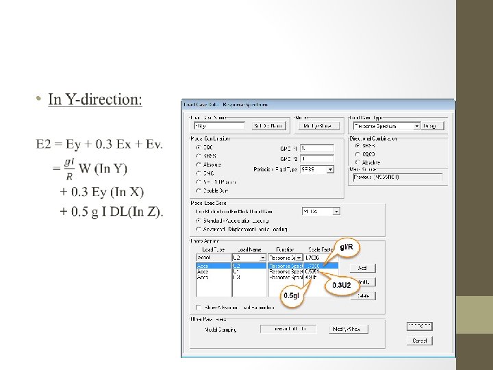
• Importance Factor: I = 1 (Non-essential building). • Lateral-Force Procedure: ü Response Spectrum Analysis. Simplified static Static
• Response Modification Factor:
• Period: Method A Method B SAP Diff% (Method B & SAP) Diff% Modified (Method A & T B) In X-direction 0. 508 1. 098 1. 071 2. 45% 53. 73% 0. 846 In Y-direction 0. 508 0. 763 0. 769 0. 78% 33. 42% 0. 763
Response Spectrum Analysis on SAP 2000 •
• Base shear: Base shear value(k. N) Modification factor Scale factor New scale factor Manually Response Spectrum In Xdirection 4168. 97 2275. 54 1. 83 1. 78 3. 26 In Ydirection 4573. 91 2931. 87 1. 56 1. 78 2. 78
Dynamic Evaluation • Evaluation of slabs: Evaluation is made for the representative slabs in ground floor. Representative one way ribbed slab Representative two way ribbed slab
• Evaluation of slabs: 1. Longitudinal Reinforcement: Positive Negative Max Mu(k. N. m/rib) As (mm 2) As min (mm 2) As existed (mm 2) Comment 21. 18 18. 05 204 183 112 402 OD OD Longitudinal reinforcement comparing in one way ribbed slab. In X-direction In Y-direction Comment Max Mu (k. N. m/r ib) As (mm 2) As min (mm 2) As existed (mm 2) Comment 402 OD 7. 52 72 112 402 OD 7. 22 70 112 402 OD Max Mu (k. N. m/ri b) As (mm 2) As min (mm 2) As existed (mm 2) Positive 9. 15 87 112 Negative 7. 05 68 112 Longitudinal reinforcement comparing in two way ribbed slab.
• Evaluation of slabs: 2. Shear Reinforcement: Shear reinforcement comparing in slabs Slab Vu ØVc Comment One way ribbed slab 15. 59 20. 66 No need for shear reinforcement Two way ribbed lab In X-direction 10. 4 20. 66 No need for shear reinforcement Two way ribbed lab In Y-direction 5. 72 20. 66 No need for shear reinforcement The slabs are OK under ultimate load design so they don’t need retrofitting.
• Evaluation of beams: Beams name 1. Longitudinal Reinforcement: Area of steel mm 2 (from SAP) Moment (KN. m) Positive (Bottom) 107. 24 Sum of area of steel 1172 B 1 Area of steel mm 2 (from Drawing) 292. 67 3614 Positive (Bottom) 100. 71 1145 B 3 206. 3 2549 Positive (Bottom) 85. 84 947 B 4 204. 79 2529 Positive (Bottom) 96. 99 1080 B 5 200. 5 2451 Positive (Bottom) 128. 89 1426 B 6 182. 06 2206 Positive (Bottom) 65. 37 709 B 7 174. 75 2100 Positive (Bottom) 74. 1 809 B 8 165. 86 1974 Positive (Bottom) 92. 53 1026 B 9 170. 74 2043 Positive (Bottom) 48. 44 607 B 10 104. 11 1167 Positive (Bottom) 38. 17 520 B 11 119. 09 1379 Positive (Bottom) 29. 05 347 B 12 33. 17 358 UD 3876 OD 2199 UD 2260 UD 2229 OD 2147 OK 1356 OD 1078 2798 924 1275 678 1582 565 1664 565 1582 452 705 Negative(Top) 1797 873 1899 Negative(Top) OK 924 1774 Negative(Top) 3743 2336 3069 Negative(Top) OD 1407 2783 Negative(Top) 3969 2160 2809 Negative(Top) OD 1809 3632 Negative(Top) 4974 2562 3531 Negative(Top) OD 2412 3476 Negative(Top) 8178 4568 3694 Negative(Top) Comment Compare with drawing 3610 4786 Negative(Top) Sum of area of steel 904
• Evaluation of beams: 2. Shear Reinforcement: Beams name Av/S from SAP No. of stirrups from Drawing Av from 2 legs of each stirrups in mm 2 B 1 B 3 B 4 B 5 B 6 B 7 B 8 B 9 B 10 B 11 B 12 0. 833 1. 143 1. 128 1. 044 0. 583 0. 928 0. 583 2. 528 0 3 2 2 2 2 2 1 301. 594 201. 062 201. 062 100. 531 Spacing (s) cm d/2 (d=28 cm ) Spacing from drawings cm Comment (d/2<S<d) ok 36. 206 17. 591 17. 825 19. 259 34. 488 21. 666 34. 488 7. 953 0 14 14 14 20 20 20 Ok OK OK OK Not Ok Ok
• Evaluation of columns: As(mm 2) Column Ø Longitudinal Reinforcement: Comment Required Existed C 1 5463 2413 UD C 2 5583 2413 UD C 3 2100 2413 OK C 4 2933 2413 UD C 5 2313 2413 OK C 6 2559 2413 UD C 7 3418 2413 UD C 8 4320 2413 UD C 9 2100 2413 OK C 10 4668 2413 UD C 11 5847 2413 UD C 12 2100 2413 OK C 13 2100 2413 OK C 14 2100 2413 OK C 15 2800 2815 OK C 16 6234 2815 UD C 17 5350 2815 UD C 18 5093 2815 UD C 19 4245 2815 UD C 20 5774 2815 UD C 21 2800 2815 OK
• Evaluation of foundations: The next tables show comparing between required and existed for: Area of steel, Settlement, Stress and Thickness. Footing F 1 F 2 F 3 F 4 F 5 F 6 Footing In x-direction (mm 2/m) Column C 15 C 20 C 6 C 16 C 14 In y-direction (mm 2/m) As(required) As(existed) Comment 1437 2340 1448 1752 2212 1080 1783 1716 1493 1440 1380 1066 OK UD UD ≈ OK 1080 1319 1080 1185 1080 1802 1702 1497 1449 1395 1062 OK OK OK ≈ OK. Thickness (cm) Column Settlement (mm) Stress (k. N/m 2) Required Existed Comment Allowable Existed Comment F 1 C 15 56 60 OK 10 9. 8 OK 200 196. 3 OK F 2 C 20 64. 1 60 Not OK 10 14. 7 Not OK 200 294. 17 Not OK F 3 F 4 C 6 C 1 47. 8 60 60 60 OK OK 10 10 9 2. 6 OK OK 200 195. 35 53. 4 OK OK F 5 C 16 64. 1 60 Not OK 10 18. 2 Not OK 200 364. 18 Not OK F 6 C 14 33. 1 60 OK 10 9 OK 200 180. 17 OK
§ Retrofitting • Retrofitting for Structural Elements: 1. Additional Elements: üShear wall: to reduce torsional effect.
2. Existing Elements: ü Beams: the area of steel existed is not enough to resist moment. o The following table shows additional longitudinal reinforcement for beams: As (mm 2) Existed Required Added Number of bars added B 6 1797 3632 1835 10Ø 16 B 8 2199 2783 584 4Ø 14 B 9 2260 3069 809 4Ø 16 Beams
o The used beams in structure are hidden beams so it’s recommended to use one-sided jackets.
üColumns: The problem of columns in the building is represented in: o Inadequate flexural strength and ductility.
o The following table shows additional longitudinal reinforcement for columns: As (mm 2) Existed Required Added Number of bars added C 1 2413 5463 3050 16Ø 16 C 2 2413 5583 3170 16Ø 16 C 4 2413 2933 520 8Ø 10 C 7 2413 3418 1005 8Ø 14 C 8 2413 4320 1907 14Ø 14 C 10 2413 4668 2255 16Ø 14 C 11 2413 5847 3434 18Ø 16 C 16 2815 6234 3419 18Ø 16 C 17 2815 5350 2535 18Ø 14 C 18 2815 5093 2278 16Ø 14 C 19 2815 4245 1430 10Ø 14 C 20 2815 5774 2959 16Ø 16 Columns
üColumns:
üFoundations: The problem of foundations in the building is represented in: o Inadequate flexural and shear strength (Moment and shear). o Stresses and settlement.
üFoundations: v Recommendations: Ø Change stories functions to decrease the load (live load) which make the foundations able to carry the loads. ØIf the retrofitting is chosen as a solution for foundations, it’s needed to: o Increase the area of footing to reduce stresses and settlement. o Increase thickness of the foundation to resist shear forces. o Reinforce the additional thickness to resist moment.
ü Soft story: Using truss bracing or reinforced infill walls to solve the problem of soft story.
Retrofitting for Non-structural elements: 1. 2. The existed infill walls need to be braced. Large openings in doors and windows, need to bracing for them as possible.
Conclusion • After making dynamic evaluation, it is noticed that the gravity combination is governed in most elements, which means that failure in buildings is occurred because they are not designed in the right way for static loads. • Its difficult to reach intermediate requirements for all elements of the building. • Detailed study and conceptual study (RVS) give the same indication for the safety of the building.