Contents Concepts of Power Flow in Power Systems


 America :")


")


 - Known")


- Slides: 39
Contents - Concepts of Power Flow in Power Systems Power Flow Formulations Definitions of Variables Steps of Power Flow Calculations 2
Concepts of Power Flow in Power Systems 3
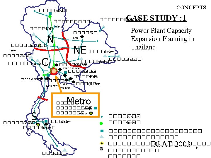
CONCEPTS Transmission System 115 k. V 230 k. V 500 k. V EGAT 2003 4
CONCEPTS Normal Operating Conditions for Power Systems • • Bus Voltage Magnitude ≈ 1. 0 p. u. Not Exceed Rated Capacities Economic Operations Compensate Reactive Power for Feasible Power Losses 5
CASE STUDY : 2 CONCEPTS The largest Power Blackout in the history of North America Blackout Area 1. Ohio 2. Michigan 3. Pennsylvania 4. New York 5. Vermont 6. Massachusetts 7. Connecticut 8. New Jersey 9. Canadian Province of Ontario 14 August 2003 : 16. 06 – 16. 12 8
CONCEPTS 9
CONCEPTS Costs of this blackout !!! Power Generation = (61, 800 MW) America : $ 4 – 10 billion (U. S. dollars) 40 million people (1/7 of U. S. ) Canada : $ 2. 3 billion (CAN. dollars) 10 million people (1/3 of CAN) 4 days for restoring the entire system 10
CONCEPTS U. S. -Canada Power System Outage Task Force The system modeling and simulation team (SMST) created steady-state power flow cases for observed August 14 system conditions starting at 15. 00– 16. 05 To be continue…. . 11
CONCEPTS Advantages of Power Flow Studies 12
CONCEPTS PROBLEM If the power of the load connected at bus 2 is known, Find the power generation and power losses. 13
CONCEPTS 0 14
CONCEPTS Prerequisite Knowledge • • • Per Unit System Bus Admittance Matrix Formulation (Ybus) Nodal Equations of Power Network Power Balance Equations Numerical Method for solving linear & nonlinear systems 15
Power Flow Formulations 16
FORMULATIONS Power-In Power-Out Bus Voltage Power Flow 17
Input Data for Power Flow FORMULATIONS • BRANCH DATA - Transmission Line : R, X, Ysh - Transformer : R, X, tap - Series Equipment’s Parameter : Capacitor, etc. • BUS DATA - Generation Schedule : P, Q, |V| - Load Schedule : P, Q - Shunt Equipment’s Parameter : C-Bank, Reactor 18
Outputs/Results of Power Flow FORMULATIONS The Steady State Operating Condition Bus Voltage i = 1, 2, …. , N Injection Flow Losses Currents 19
Definitions of Variables bus i bus j Power Flow : Power Injection : 20
DEFINITIONS Power Injection Generation bus i bus j Load Power Injection bus k 21
DEFINITIONS Current Injection : Injected Current at bus i 22
DEFINITIONS Power Injection Equation For bus i : 23
DEFINITIONS Power Injection Equations Rectangular Form : 24
DEFINITIONS Power Injection Equations Polar Form 25
DEFINITIONS Power Balance Equation IN OUT LOSSES 26
DEFINITIONS Bus Type Classification 1. Slack Bus (Reference bus / Swing bus) - Known : |V|, δ=0 Unknown : Pi, Qi 2. Voltage Controlled Bus (Generator bus/PV bus) Known : Pi, |V| Unknown : δ, Qi 3. Load Bus (PQ bus) Known : Pi, Qi Unknown : |V|, δ 27
28
29
DEFINITIONS Bus Type Classification Slack Bus Load Bus V-Controlled Bus 30
DEFINITIONS Number of Equations and Variables For 1 bus: 4 variables : 2 equations For N bus: 4 N variables : 2 N equations Bus Type Known Unknown Slack P-V P-Q V, P, V P, Q Q, V, NPV = Number of P-V bus NPQ = Number of P-Q bus 2 N variables Unknown (V, ) = 2 N - NPV - 2 31
DEFINITIONS Power Mismatch Specified Mismatch Calculation 32
Steps of Power Flow Calculations STEP 0 STEP 1 STEP 2 STEP 3 STEP 4 STEP 5 Calculate Per Unit Values on the same base Find Bus Admittance Matrix (Ybus) Classify Bus Type Formulate Power Injection Equations Solve Power Injection Equations Calculate Power Flows in the System 33
CALCULATION STEPS STEP 0 Calculate branch data and bus data in Per Unit on the same base STEP 1 Find Bus Admittance Matrix (Ybus) 34
CALCULATION STEPS STEP 2 Classify Bus Type Load Bus Slack Bus V-Controlled Bus 35
CALCULATION STEPS STEP 3 Formulate Power Injection Equations Slack Bus No Equations P-V Bus P-Q Bus 36
CALCULATION STEPS STEP 4 Solve Power Injection Equations Numerical Method : Iterative Computation 1. Gauss-Seidel Method - Accelerated Gauss-Seidel 2. Newton-Raphson Method - Decouple Power Flow - Fast Decouple Power Flow 37
CALCULATION STEPS STEP 5 Calculate Power Flows in the system bus i bus j Flow bus i j : Flow bus j i : Line Power Losses = 38
� � � ! � � � n � o o � S � ng i m Co The Gauss-Seidel Power Flow 39