
Contemporary Logic Design Prog Steering Logic Chapter 4
- Slides: 75
Contemporary Logic Design Prog. & Steering Logic Chapter # 4: Programmable and Steering Logic Contemporary Logic Design Randy H. Katz University of California, Berkeley June 1993 © R. H. Katz Transparency No. 4 -1
Chapter Overview Contemporary Logic Design Prog. & Steering Logic • PALs and PLAs • Non-Gate Logic Switch Logic Multiplexers/Selecters and Decoders Tri-State Gates/Open Collector Gates ROM • Combinational Logic Design Problems Seven Segment Display Decoder Process Line Controller Logical Function Unit Barrel Shifter © R. H. Katz Transparency No. 4 -2
PALs and PLAs Contemporary Logic Design Prog. & Steering Logic Pre-fabricated building block of many AND/OR gates (or NOR, NAND) "Personalized" by making or breaking connections among the gates Programmable Array Block Diagram for Sum of Products Form © R. H. Katz Transparency No. 4 -3
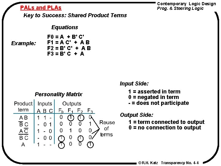
PALs and PLAs Key to Success: Shared Product Terms Contemporary Logic Design Prog. & Steering Logic Equations Example: F 0 = A + B' C' F 1 = A C' + A B F 2 = B' C' + A B F 3 = B' C + A Personality Matrix Input Side: 1 = asserted in term 0 = negated in term - = does not participate Output Side: 1 = term connected to output 0 = no connection to output © R. H. Katz Transparency No. 4 -4
PALs and PLAs Contemporary Logic Design Prog. & Steering Logic Example Continued All possible connections are available before programming © R. H. Katz Transparency No. 4 -5
PALs and PLAs Contemporary Logic Design Prog. & Steering Logic Example Continued Unwanted connections are "blown" Note: some array structures work by making connections rather than breaking them © R. H. Katz Transparency No. 4 -6
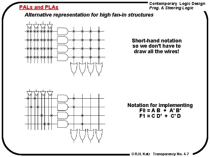
Contemporary Logic Design PALs and PLAs Prog. & Steering Logic Alternative representation for high fan-in structures Short-hand notation so we don't have to draw all the wires! Notation for implementing F 0 = A B + A' B' F 1 = C D' + C' D © R. H. Katz Transparency No. 4 -7
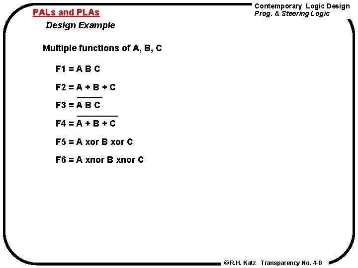
PALs and PLAs Design Example Contemporary Logic Design Prog. & Steering Logic Multiple functions of A, B, C F 1 = A B C F 2 = A + B + C F 3 = A B C F 4 = A + B + C F 5 = A xor B xor C F 6 = A xnor B xnor C © R. H. Katz Transparency No. 4 -8
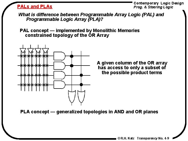
PALs and PLAs Contemporary Logic Design Prog. & Steering Logic What is difference between Programmable Array Logic (PAL) and Programmable Logic Array (PLA)? PAL concept — implemented by Monolithic Memories constrained topology of the OR Array A given column of the OR array has access to only a subset of the possible product terms PLA concept — generalized topologies in AND and OR planes © R. H. Katz Transparency No. 4 -9
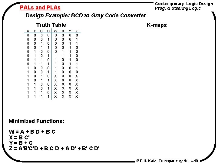
PALs and PLAs Design Example: BCD to Gray Code Converter Truth Table Contemporary Logic Design Prog. & Steering Logic K-maps Minimized Functions: W = A + B D + B C X = B C' Y = B + C Z = A'B'C'D + B C D + A D' + B' C D' © R. H. Katz Transparency No. 4 -10
PALs and PLAs Contemporary Logic Design Prog. & Steering Logic Programmed PAL: 4 product terms per each OR gate © R. H. Katz Transparency No. 4 -11
Contemporary Logic Design Prog. & Steering Logic PALs and PLAs Code Converter Discrete Gate Implementation 4 SSI Packages vs. 1 PLA/PAL Package! © R. H. Katz Transparency No. 4 -12
PALs and PLAs Another Example: Magnitude Comparator Contemporary Logic Design Prog. & Steering Logic © R. H. Katz Transparency No. 4 -13
Contemporary Logic Design Prog. & Steering Logic Non-Gate Logic Introduction AND-OR-Invert PAL/PLA Generalized Building Blocks Beyond Simple Gates Kinds of "Non-gate logic": • switching circuits built from CMOS transmission gates • multiplexer/selecter functions • decoders • tri-state and open collector gates • read-only memories © R. H. Katz Transparency No. 4 -14
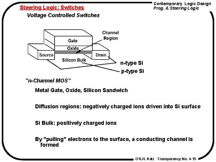
Contemporary Logic Design Prog. & Steering Logic: Switches Voltage Controlled Switches n-type Si p-type Si "n-Channel MOS" Metal Gate, Oxide, Silicon Sandwich Diffusion regions: negatively charged ions driven into Si surface Si Bulk: positively charged ions By "pulling" electrons to the surface, a conducting channel is formed © R. H. Katz Transparency No. 4 -15
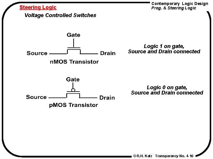
Steering Logic Voltage Controlled Switches Contemporary Logic Design Prog. & Steering Logic 1 on gate, Source and Drain connected Logic 0 on gate, Source and Drain connected © R. H. Katz Transparency No. 4 -16
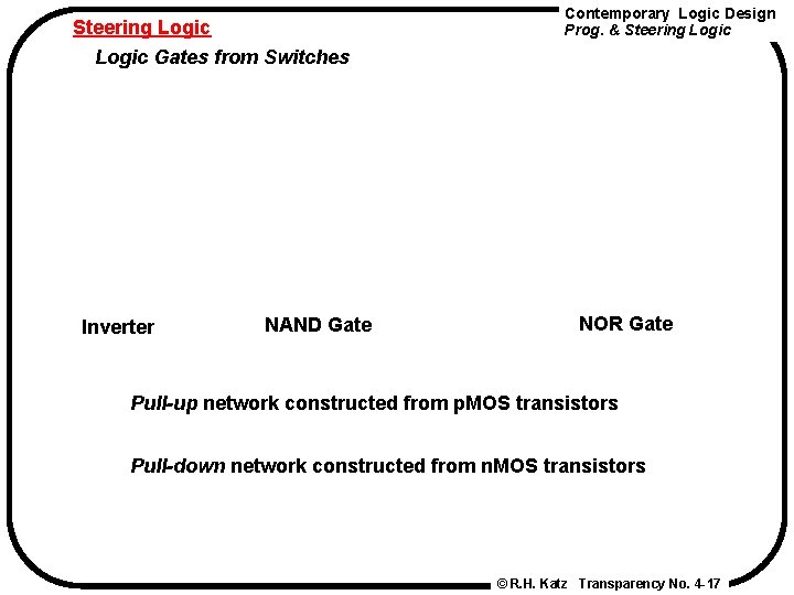
Steering Logic Gates from Switches Inverter NAND Gate Contemporary Logic Design Prog. & Steering Logic NOR Gate Pull-up network constructed from p. MOS transistors Pull-down network constructed from n. MOS transistors © R. H. Katz Transparency No. 4 -17
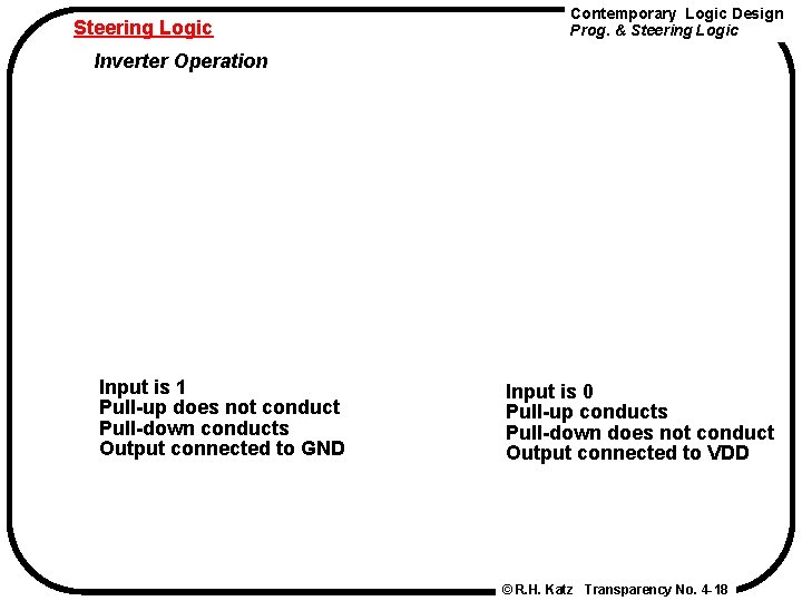
Steering Logic Contemporary Logic Design Prog. & Steering Logic Inverter Operation Input is 1 Pull-up does not conduct Pull-down conducts Output connected to GND Input is 0 Pull-up conducts Pull-down does not conduct Output connected to VDD © R. H. Katz Transparency No. 4 -18
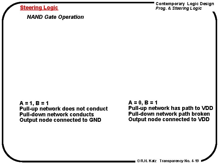
Steering Logic Contemporary Logic Design Prog. & Steering Logic NAND Gate Operation A = 1, B = 1 Pull-up network does not conduct Pull-down network conducts Output node connected to GND A = 0, B = 1 Pull-up network has path to VDD Pull-down network path broken Output node connected to VDD © R. H. Katz Transparency No. 4 -19
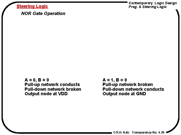
Steering Logic Contemporary Logic Design Prog. & Steering Logic NOR Gate Operation A = 0, B = 0 Pull-up network conducts Pull-down network broken Output node at VDD A = 1, B = 0 Pull-up network broken Pull-down network conducts Output node at GND © R. H. Katz Transparency No. 4 -20
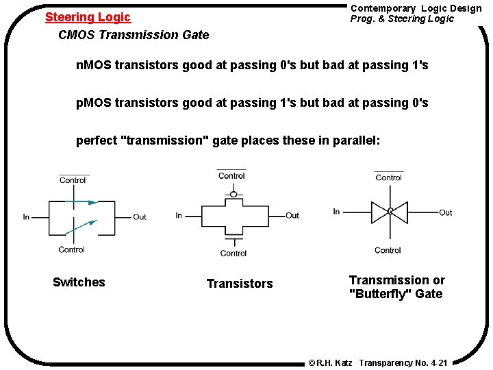
Steering Logic CMOS Transmission Gate Contemporary Logic Design Prog. & Steering Logic n. MOS transistors good at passing 0's but bad at passing 1's p. MOS transistors good at passing 1's but bad at passing 0's perfect "transmission" gate places these in parallel: Switches Transistors Transmission or "Butterfly" Gate © R. H. Katz Transparency No. 4 -21
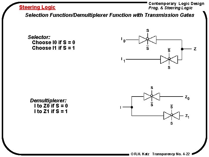
Contemporary Logic Design Steering Logic Prog. & Steering Logic Selection Function/Demultiplexer Function with Transmission Gates Selector: Choose I 0 if S = 0 Choose I 1 if S = 1 Demultiplexer: I to Z 0 if S = 0 I to Z 1 if S = 1 © R. H. Katz Transparency No. 4 -22
Steering Logic Contemporary Logic Design Prog. & Steering Logic Use of Multiplexer/Demultiplexer in Digital Systems So far, we've only seen point-to-point connections among gates Mux/Demux used to implement multiple source/multiple destination interconnect © R. H. Katz Transparency No. 4 -23
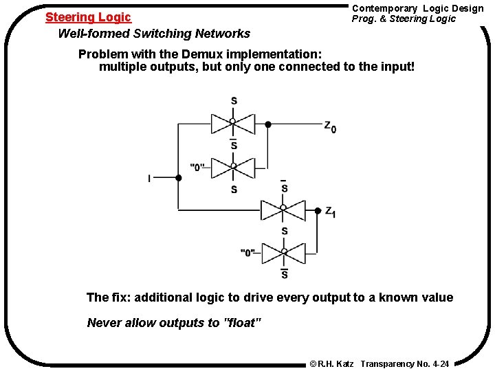
Steering Logic Well-formed Switching Networks Contemporary Logic Design Prog. & Steering Logic Problem with the Demux implementation: multiple outputs, but only one connected to the input! The fix: additional logic to drive every output to a known value Never allow outputs to "float" © R. H. Katz Transparency No. 4 -24
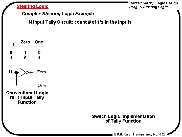
Contemporary Logic Design Prog. & Steering Logic Complex Steering Logic Example N Input Tally Circuit: count # of 1's in the inputs Conventional Logic for 1 Input Tally Function Switch Logic Implementation of Tally Function © R. H. Katz Transparency No. 4 -25
Contemporary Logic Design Prog. & Steering Logic Complex Steering Logic Example Operation of the 1 Input Tally Circuit Input is 0, straight through switches enabled © R. H. Katz Transparency No. 4 -26
Steering Logic Contemporary Logic Design Prog. & Steering Logic Complex Steering Logic Example Operation of 1 input Tally Circuit Input = 1, diagonal switches enabled © R. H. Katz Transparency No. 4 -27
Contemporary Logic Design Prog. & Steering Logic Complex Steering Logic Example Extension to the 2 -input case Conventional logic implementation © R. H. Katz Transparency No. 4 -28
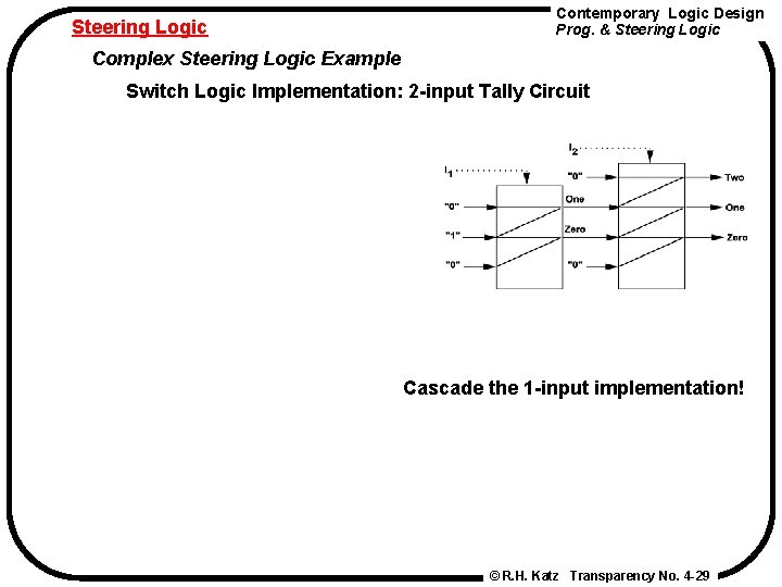
Steering Logic Contemporary Logic Design Prog. & Steering Logic Complex Steering Logic Example Switch Logic Implementation: 2 -input Tally Circuit Cascade the 1 -input implementation! © R. H. Katz Transparency No. 4 -29
Steering Logic Complex Steering Logic Example Contemporary Logic Design Prog. & Steering Logic Operation of 2 -input implementation © R. H. Katz Transparency No. 4 -30
Multiplexers/Selectors Contemporary Logic Design Prog. & Steering Logic Use of Multiplexers/Selectors Multi-point connections Multiple input sources Multiple output destinations © R. H. Katz Transparency No. 4 -31
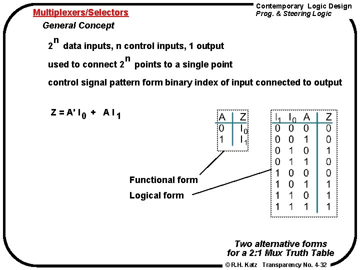
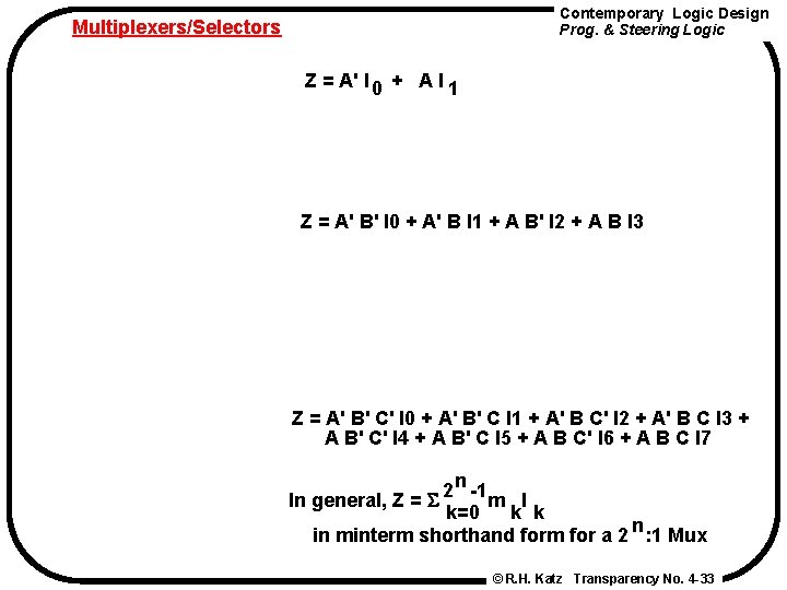
Contemporary Logic Design Prog. & Steering Logic Multiplexers/Selectors General Concept n 2 data inputs, n control inputs, 1 output n used to connect 2 points to a single point control signal pattern form binary index of input connected to output Z = A' I + A I 0 1 Functional form Logical form Two alternative forms for a 2: 1 Mux Truth Table © R. H. Katz Transparency No. 4 -32
Contemporary Logic Design Prog. & Steering Logic Multiplexers/Selectors Z = A' I + A I 0 1 Z = A' B' I 0 + A' B I 1 + A B' I 2 + A B I 3 Z = A' B' C' I 0 + A' B' C I 1 + A' B C' I 2 + A' B C I 3 + A B' C' I 4 + A B' C I 5 + A B C' I 6 + A B C I 7 n 2 -1 In general, Z = m I k=0 k k n in minterm shorthand form for a 2 : 1 Mux © R. H. Katz Transparency No. 4 -33
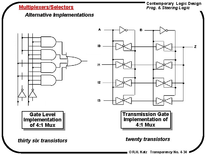
Multiplexers/Selectors Alternative Implementations Gate Level Implementation of 4: 1 Mux thirty six transistors Contemporary Logic Design Prog. & Steering Logic Transmission Gate Implementation of 4: 1 Mux twenty transistors © R. H. Katz Transparency No. 4 -34
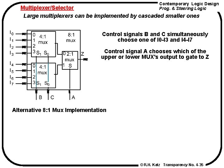
Contemporary Logic Design Multiplexer/Selector Prog. & Steering Logic Large multiplexers can be implemented by cascaded smaller ones Control signals B and C simultaneously choose one of I 0 -I 3 and I 4 -I 7 Control signal A chooses which of the upper or lower MUX's output to gate to Z Alternative 8: 1 Mux Implementation © R. H. Katz Transparency No. 4 -35
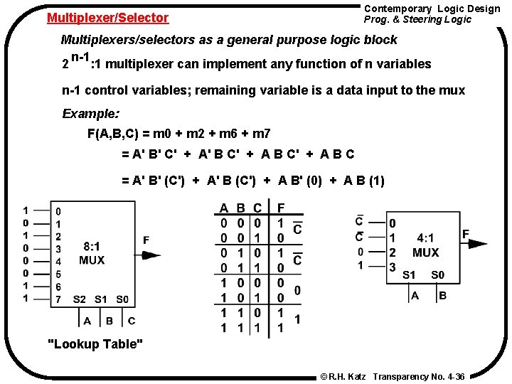
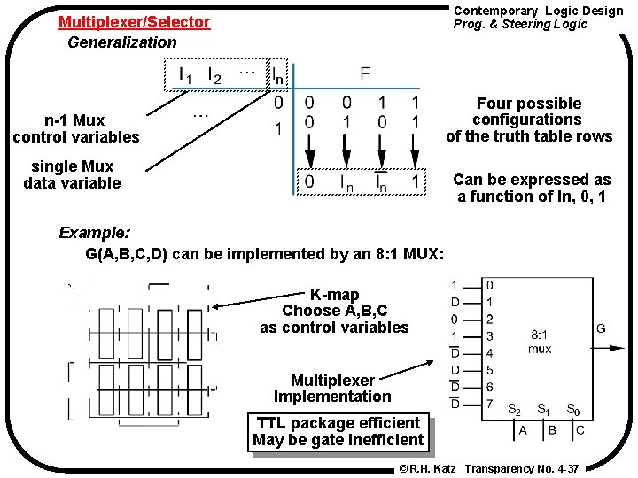
Contemporary Logic Design Prog. & Steering Logic Multiplexer/Selector Multiplexers/selectors as a general purpose logic block n-1 2 : 1 multiplexer can implement any function of n variables n-1 control variables; remaining variable is a data input to the mux Example: F(A, B, C) = m 0 + m 2 + m 6 + m 7 = A' B' C' + A' B C' + A B C = A' B' (C') + A' B (C') + A B' (0) + A B (1) "Lookup Table" © R. H. Katz Transparency No. 4 -36
Contemporary Logic Design Prog. & Steering Logic Multiplexer/Selector Generalization Four possible configurations of the truth table rows n-1 Mux control variables single Mux data variable Can be expressed as a function of In, 0, 1 Example: G(A, B, C, D) can be implemented by an 8: 1 MUX: K-map Choose A, B, C as control variables Multiplexer Implementation TTL package efficient May be gate inefficient © R. H. Katz Transparency No. 4 -37
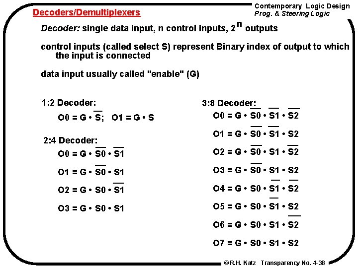
Decoders/Demultiplexers Contemporary Logic Design Prog. & Steering Logic n Decoder: single data input, n control inputs, 2 outputs control inputs (called select S) represent Binary index of output to which the input is connected data input usually called "enable" (G) 1: 2 Decoder: O 0 = G • S; O 1 = G • S 2: 4 Decoder: O 0 = G • S 0 • S 1 3: 8 Decoder: O 0 = G • S 0 • S 1 • S 2 O 1 = G • S 0 • S 1 • S 2 O 2 = G • S 0 • S 1 • S 2 O 1 = G • S 0 • S 1 O 3 = G • S 0 • S 1 • S 2 O 2 = G • S 0 • S 1 O 4 = G • S 0 • S 1 • S 2 O 3 = G • S 0 • S 1 O 5 = G • S 0 • S 1 • S 2 O 6 = G • S 0 • S 1 • S 2 O 7 = G • S 0 • S 1 • S 2 © R. H. Katz Transparency No. 4 -38
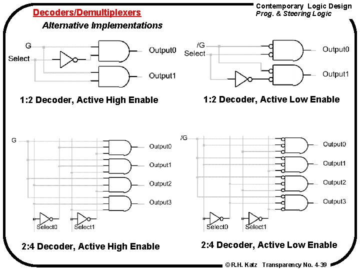
Decoders/Demultiplexers Alternative Implementations Contemporary Logic Design Prog. & Steering Logic 1: 2 Decoder, Active High Enable 1: 2 Decoder, Active Low Enable 2: 4 Decoder, Active High Enable 2: 4 Decoder, Active Low Enable © R. H. Katz Transparency No. 4 -39
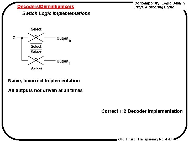
Decoders/Demultiplexers Switch Logic Implementations Contemporary Logic Design Prog. & Steering Logic Naive, Incorrect Implementation All outputs not driven at all times Correct 1: 2 Decoder Implementation © R. H. Katz Transparency No. 4 -40
Decoders/Demultiplexers Switch Implementation of 2: 4 Decoder Contemporary Logic Design Prog. & Steering Logic Operation of 2: 4 Decoder S 0 = 0, S 1 = 0 one straight thru path three diagonal paths © R. H. Katz Transparency No. 4 -41
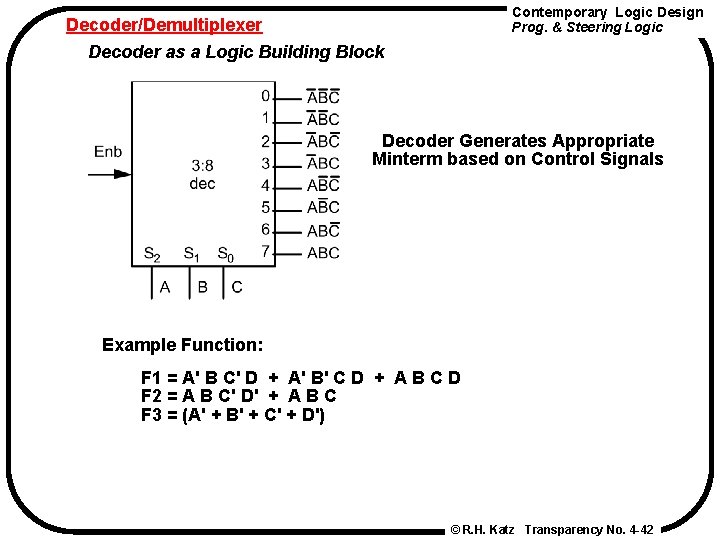
Contemporary Logic Design Prog. & Steering Logic Decoder/Demultiplexer Decoder as a Logic Building Block Decoder Generates Appropriate Minterm based on Control Signals Example Function: F 1 = A' B C' D + A' B' C D + A B C D F 2 = A B C' D' + A B C F 3 = (A' + B' + C' + D') © R. H. Katz Transparency No. 4 -42
Decoder/Demultiplexer Contemporary Logic Design Prog. & Steering Logic Decoder as a Logic Building Block If active low enable, then use NAND gates! © R. H. Katz Transparency No. 4 -43
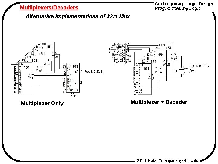
Multiplexers/Decoders Contemporary Logic Design Prog. & Steering Logic Alternative Implementations of 32: 1 Mux Multiplexer Only Multiplexer + Decoder © R. H. Katz Transparency No. 4 -44
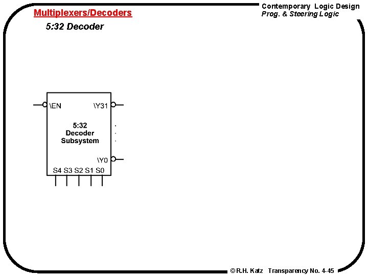
Multiplexers/Decoders 5: 32 Decoder Contemporary Logic Design Prog. & Steering Logic © R. H. Katz Transparency No. 4 -45
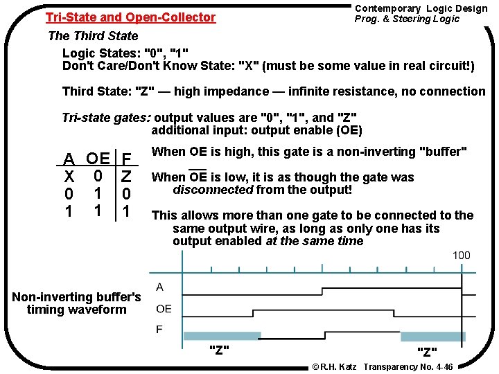
Contemporary Logic Design Tri-State and Open-Collector Prog. & Steering Logic The Third State Logic States: "0", "1" Don't Care/Don't Know State: "X" (must be some value in real circuit!) Third State: "Z" — high impedance — infinite resistance, no connection Tri-state gates: output values are "0", "1", and "Z" additional input: output enable (OE) A OE F X 0 Z 0 1 1 1 When OE is high, this gate is a non-inverting "buffer" When OE is low, it is as though the gate was disconnected from the output! This allows more than one gate to be connected to the same output wire, as long as only one has its output enabled at the same time Non-inverting buffer's timing waveform "Z" © R. H. Katz Transparency No. 4 -46
Tri-state and Open Collector Contemporary Logic Design Prog. & Steering Logic Using tri-state gates to implement an economical multiplexer: When Select. Input is asserted high Input 1 is connected to F When Select. Input is driven low Input 0 is connected to F This is essentially a 2: 1 Mux © R. H. Katz Transparency No. 4 -47
Contemporary Logic Design Prog. & Steering Logic Tri-state and Open Collector Alternative Tri-state Fragment Active low tri-state enables plus inverting tri-state buffers Switch Level Implementation of tri-state gate © R. H. Katz Transparency No. 4 -48
Tri-State and Open Collector 4: 1 Multiplexer, Revisited Contemporary Logic Design Prog. & Steering Logic Decoder + 4 tri-state Gates © R. H. Katz Transparency No. 4 -49
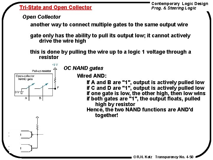
Tri-State and Open Collector Contemporary Logic Design Prog. & Steering Logic Open Collector another way to connect multiple gates to the same output wire gate only has the ability to pull its output low; it cannot actively drive the wire high this is done by pulling the wire up to a logic 1 voltage through a resistor OC NAND gates Wired AND: If A and B are "1", output is actively pulled low if C and D are "1", output is actively pulled low if one gate is low, the other high, then low wins if both gates are "1", the output floats, pulled high by resistor Hence, the two NAND functions are AND'd together! © R. H. Katz Transparency No. 4 -50
Contemporary Logic Design Prog. & Steering Logic Tri-State and Open Collector 4: 1 Multiplexer Decoder + 4 Open Collector Gates © R. H. Katz Transparency No. 4 -51
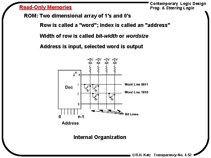
Contemporary Logic Design Prog. & Steering Logic Read-Only Memories ROM: Two dimensional array of 1's and 0's Row is called a "word"; index is called an "address" Width of row is called bit-width or wordsize Address is input, selected word is output Internal Organization © R. H. Katz Transparency No. 4 -52
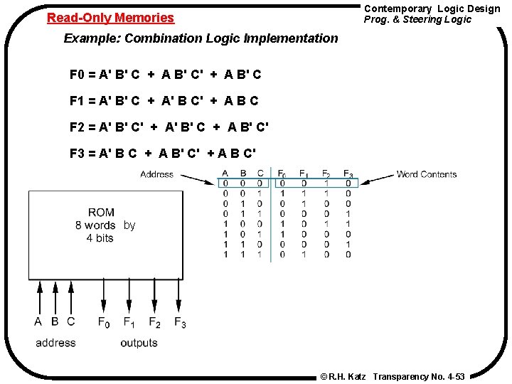
Contemporary Logic Design Prog. & Steering Logic Read-Only Memories Example: Combination Logic Implementation F 0 = A' B' C + A B' C' + A B' C F 1 = A' B' C + A' B C' + A B C F 2 = A' B' C' + A' B' C + A B' C' F 3 = A' B C + A B' C' + A B C' by © R. H. Katz Transparency No. 4 -53
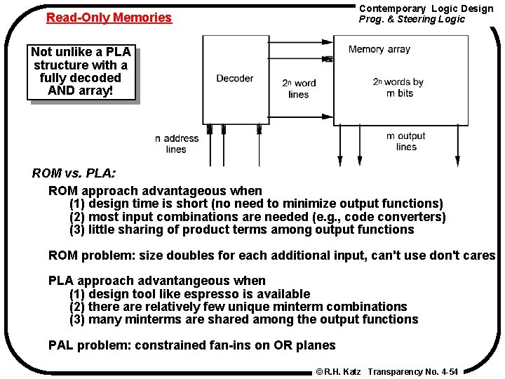
Contemporary Logic Design Prog. & Steering Logic Read-Only Memories Not unlike a PLA structure with a fully decoded AND array! ROM vs. PLA: ROM approach advantageous when (1) design time is short (no need to minimize output functions) (2) most input combinations are needed (e. g. , code converters) (3) little sharing of product terms among output functions ROM problem: size doubles for each additional input, can't use don't cares PLA approach advantangeous when (1) design tool like espresso is available (2) there are relatively few unique minterm combinations (3) many minterms are shared among the output functions PAL problem: constrained fan-ins on OR planes © R. H. Katz Transparency No. 4 -54
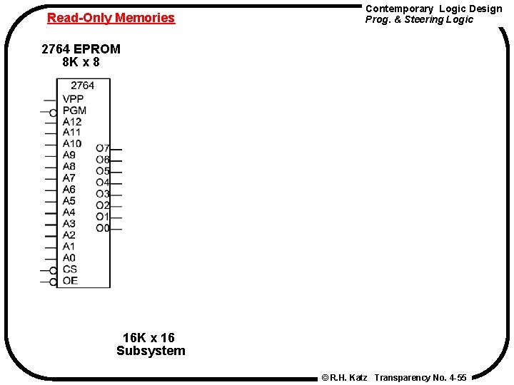
Read-Only Memories Contemporary Logic Design Prog. & Steering Logic 2764 EPROM 8 K x 8 16 K x 16 Subsystem © R. H. Katz Transparency No. 4 -55
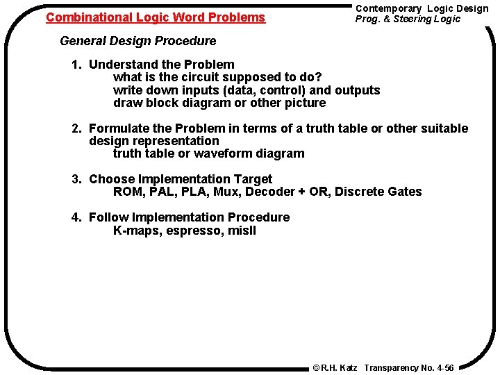
Combinational Logic Word Problems Contemporary Logic Design Prog. & Steering Logic General Design Procedure 1. Understand the Problem what is the circuit supposed to do? write down inputs (data, control) and outputs draw block diagram or other picture 2. Formulate the Problem in terms of a truth table or other suitable design representation truth table or waveform diagram 3. Choose Implementation Target ROM, PAL, PLA, Mux, Decoder + OR, Discrete Gates 4. Follow Implementation Procedure K-maps, espresso, mis. II © R. H. Katz Transparency No. 4 -56
Combinational Logic Word Problems Process Line Control Problem Contemporary Logic Design Prog. & Steering Logic Statement of the Problem Rods of varying length (+/-10%) travel on conveyor belt Mechanical arm pushes rods within spec (+/-5%) to one side Second arm pushes rods too long to other side Rods too short stay on belt 3 light barriers (light source + photocell) as sensors Design combinational logic to activate the arms Understanding the Problem Inputs are three sensors, outputs are two arm control signals Assume sensor reads "1" when tripped, "0" otherwise Call sensors A, B, C Draw a picture! © R. H. Katz Transparency No. 4 -57
Combinational Logic Word Problems Process Control Problem Contemporary Logic Design Prog. & Steering Logic Where to place the light sensors A, B, and C to distinguish among the three cases? Assume that A detects the leading edge of the rod on the conveyor © R. H. Katz Transparency No. 4 -58
Combinational Logic Word Problems Process Control Problem Contemporary Logic Design Prog. & Steering Logic A to B distance place apart at specification - 5% A to C distance placed apart at specification +5% © R. H. Katz Transparency No. 4 -59
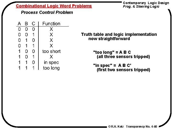
Combinational Logic Word Problems Process Control Problem Contemporary Logic Design Prog. & Steering Logic Truth table and logic implementation now straightforward "too long" = A B C (all three sensors tripped) "in spec" = A B C' (first two sensors tripped) © R. H. Katz Transparency No. 4 -60
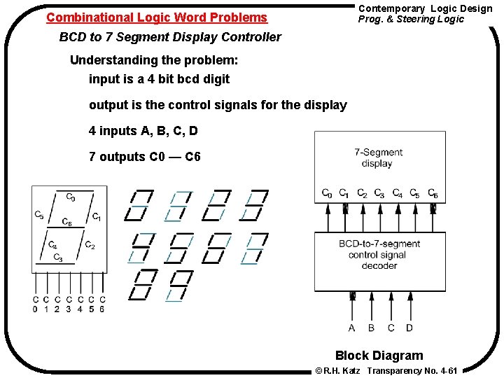
Contemporary Logic Design Prog. & Steering Logic Combinational Logic Word Problems BCD to 7 Segment Display Controller Understanding the problem: input is a 4 bit bcd digit output is the control signals for the display 4 inputs A, B, C, D 7 outputs C 0 — C 6 Block Diagram © R. H. Katz Transparency No. 4 -61
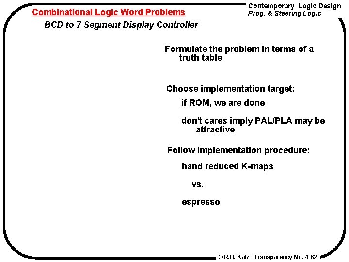
Contemporary Logic Design Prog. & Steering Logic Combinational Logic Word Problems BCD to 7 Segment Display Controller Formulate the problem in terms of a truth table Choose implementation target: if ROM, we are don't cares imply PAL/PLA may be attractive Follow implementation procedure: hand reduced K-maps vs. espresso © R. H. Katz Transparency No. 4 -62
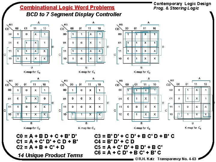
Combinational Logic Word Problems BCD to 7 Segment Display Controller C 0 = A + B D + C + B' D' C 1 = A + C' D' + C D + B' C 2 = A + B + C' + D 14 Unique Product Terms Contemporary Logic Design Prog. & Steering Logic C 3 = B' D' + C D' + B C' D + B' C C 4 = B' D' + C D C 5 = A + C' D' + B C' C 6 = A + C D' + B C' + B' C © R. H. Katz Transparency No. 4 -63
Combinational Logic Word Problems BCD to 7 Segment Display Controller Contemporary Logic Design Prog. & Steering Logic 16 H 8 PAL Can Implement the function © R. H. Katz Transparency No. 4 -64
Combinational Logic Word Problems BCD to 7 Segment Display Controller Contemporary Logic Design Prog. & Steering Logic 14 H 8 PAL Cannot Implement the function © R. H. Katz Transparency No. 4 -65
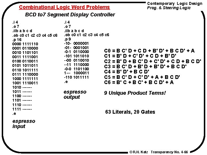
Combinational Logic Word Problems BCD to 7 Segment Display Controller. i 4. o 7. ilb a b c d. ob c 0 c 1 c 2 c 3 c 4 c 5 c 6. p 16 0000 1111110 0001 0110000 0010 1101101 0011 1111001 0100 0110011 0101 1011011 0110 1011111 0111 1110000 1111111 1001 1110011 1010 ------1011 ------1100 ------1101 ------1110 ------1111 ------. e Contemporary Logic Design Prog. & Steering Logic . i 4. o 7. ilb a b c d. ob c 0 c 1 c 2 c 3 c 4 c 5 c 6. p 9 -10 - 0000001 -01 - 0001001 C 0 = B C' D + C D + B' D' + B C D' + A -0 -1 0110000 -101 1011010 C 1 = B' D + C' D' + C D + B' D' --00 0110010 C 2 = B' D + B C' D + C' D' + C D + B C D' --11 1110000 C 3 = B C' D + B' D' + B C D' -0 -0 1101100 C 4 = B' D' + B C D' 1 --- 1000011 -110 1011111 C 5 = B C' D + C' D' + A + B C D'. e C 6 = B' C + B C' + B C D' + A espresso output 9 Unique Product Terms! 63 Literals, 20 Gates espresso input © R. H. Katz Transparency No. 4 -66
Combinational Logic Word Problems BCD to 7 Segment Display Controller Contemporary Logic Design Prog. & Steering Logic PLA Implementation © R. H. Katz Transparency No. 4 -67
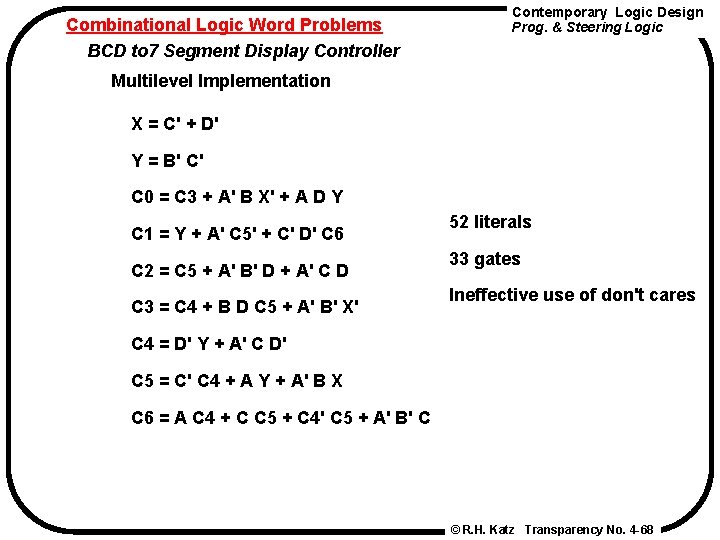
Combinational Logic Word Problems BCD to 7 Segment Display Controller Contemporary Logic Design Prog. & Steering Logic Multilevel Implementation X = C' + D' Y = B' C' C 0 = C 3 + A' B X' + A D Y C 1 = Y + A' C 5' + C' D' C 6 C 2 = C 5 + A' B' D + A' C D C 3 = C 4 + B D C 5 + A' B' X' 52 literals 33 gates Ineffective use of don't cares C 4 = D' Y + A' C D' C 5 = C' C 4 + A Y + A' B X C 6 = A C 4 + C C 5 + C 4' C 5 + A' B' C © R. H. Katz Transparency No. 4 -68
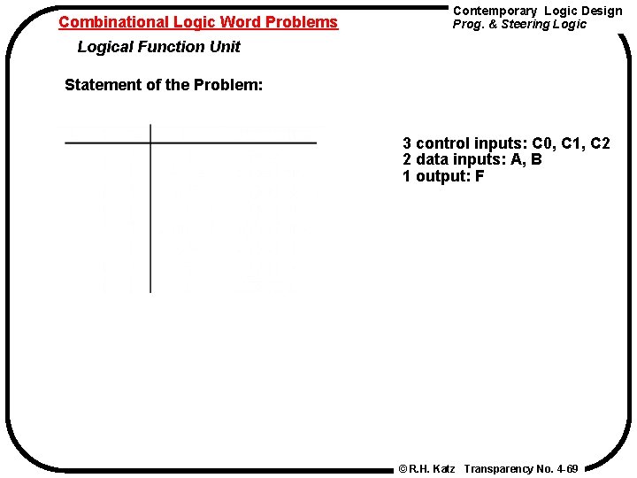
Combinational Logic Word Problems Contemporary Logic Design Prog. & Steering Logical Function Unit Statement of the Problem: 3 control inputs: C 0, C 1, C 2 2 data inputs: A, B 1 output: F © R. H. Katz Transparency No. 4 -69
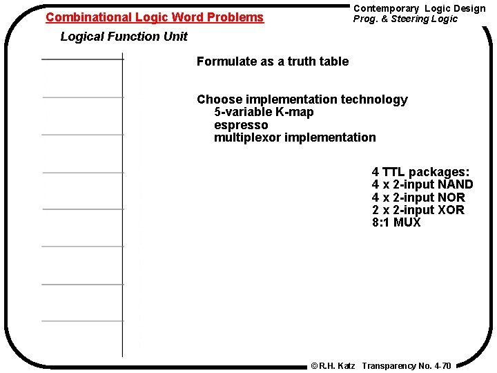
Contemporary Logic Design Prog. & Steering Logic Combinational Logic Word Problems Logical Function Unit Formulate as a truth table Choose implementation technology 5 -variable K-map espresso multiplexor implementation 4 TTL packages: 4 x 2 -input NAND 4 x 2 -input NOR 2 x 2 -input XOR 8: 1 MUX © R. H. Katz Transparency No. 4 -70
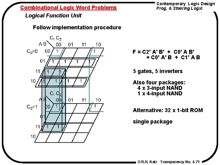
Combinational Logic Word Problems Logical Function Unit Contemporary Logic Design Prog. & Steering Logic Follow implementation procedure F = C 2' A' B' + C 0' A B' + C 0' A' B + C 1' A B 5 gates, 5 inverters Also four packages: 4 x 3 -input NAND 1 x 4 -input NAND Alternative: 32 x 1 -bit ROM single package © R. H. Katz Transparency No. 4 -71
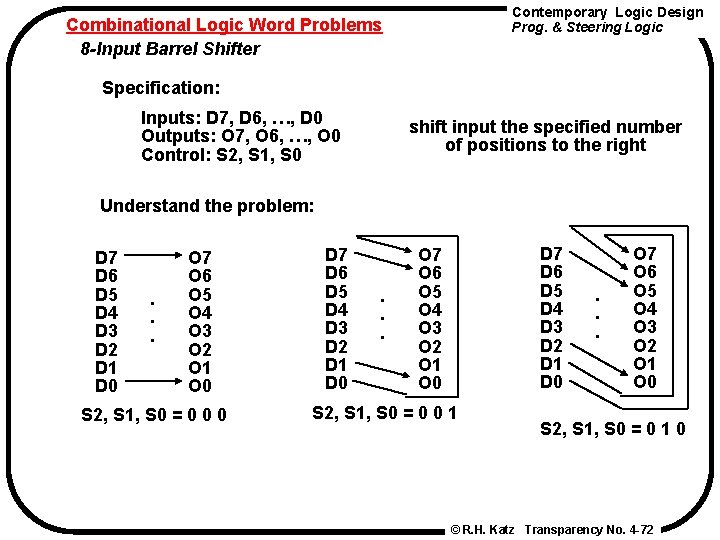
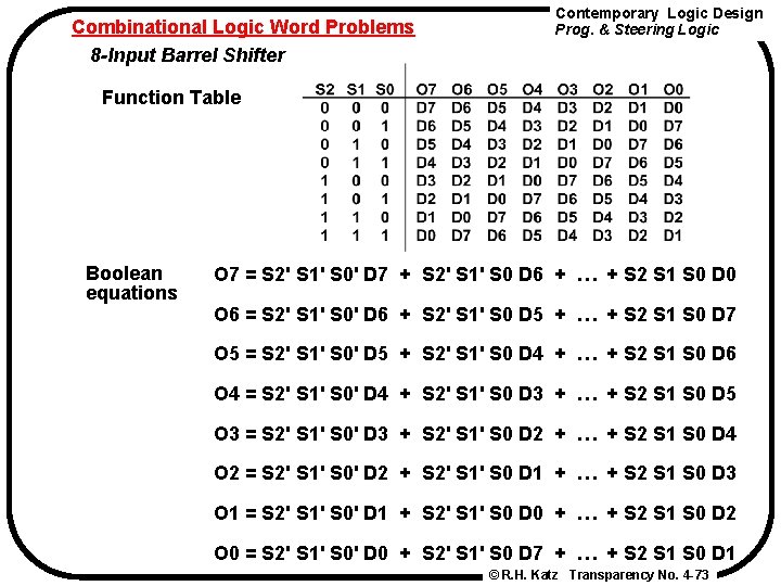
Contemporary Logic Design Prog. & Steering Logic Combinational Logic Word Problems 8 -Input Barrel Shifter Specification: Inputs: D 7, D 6, …, D 0 Outputs: O 7, O 6, …, O 0 Control: S 2, S 1, S 0 shift input the specified number of positions to the right Understand the problem: D 7 D 6 D 5 D 4 D 3 D 2 D 1 D 0 . . . O 7 O 6 O 5 O 4 O 3 O 2 O 1 O 0 S 2, S 1, S 0 = 0 0 0 D 7 D 6 D 5 D 4 D 3 D 2 D 1 D 0 . . . D 7 D 6 D 5 D 4 D 3 D 2 D 1 D 0 O 7 O 6 O 5 O 4 O 3 O 2 O 1 O 0 S 2, S 1, S 0 = 0 0 1 . . . O 7 O 6 O 5 O 4 O 3 O 2 O 1 O 0 S 2, S 1, S 0 = 0 1 0 © R. H. Katz Transparency No. 4 -72
Combinational Logic Word Problems 8 -Input Barrel Shifter Contemporary Logic Design Prog. & Steering Logic Function Table Boolean equations O 7 = S 2' S 1' S 0' D 7 + S 2' S 1' S 0 D 6 + … + S 2 S 1 S 0 D 0 O 6 = S 2' S 1' S 0' D 6 + S 2' S 1' S 0 D 5 + … + S 2 S 1 S 0 D 7 O 5 = S 2' S 1' S 0' D 5 + S 2' S 1' S 0 D 4 + … + S 2 S 1 S 0 D 6 O 4 = S 2' S 1' S 0' D 4 + S 2' S 1' S 0 D 3 + … + S 2 S 1 S 0 D 5 O 3 = S 2' S 1' S 0' D 3 + S 2' S 1' S 0 D 2 + … + S 2 S 1 S 0 D 4 O 2 = S 2' S 1' S 0' D 2 + S 2' S 1' S 0 D 1 + … + S 2 S 1 S 0 D 3 O 1 = S 2' S 1' S 0' D 1 + S 2' S 1' S 0 D 0 + … + S 2 S 1 S 0 D 2 O 0 = S 2' S 1' S 0' D 0 + S 2' S 1' S 0 D 7 + … + S 2 S 1 S 0 D 1 © R. H. Katz Transparency No. 4 -73
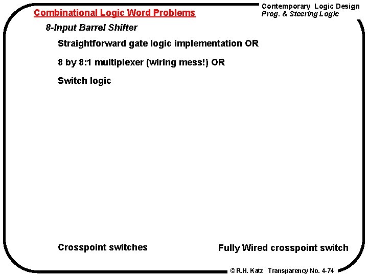
Contemporary Logic Design Prog. & Steering Logic Combinational Logic Word Problems 8 -Input Barrel Shifter Straightforward gate logic implementation OR 8 by 8: 1 multiplexer (wiring mess!) OR Switch logic Crosspoint switches Fully Wired crosspoint switch © R. H. Katz Transparency No. 4 -74
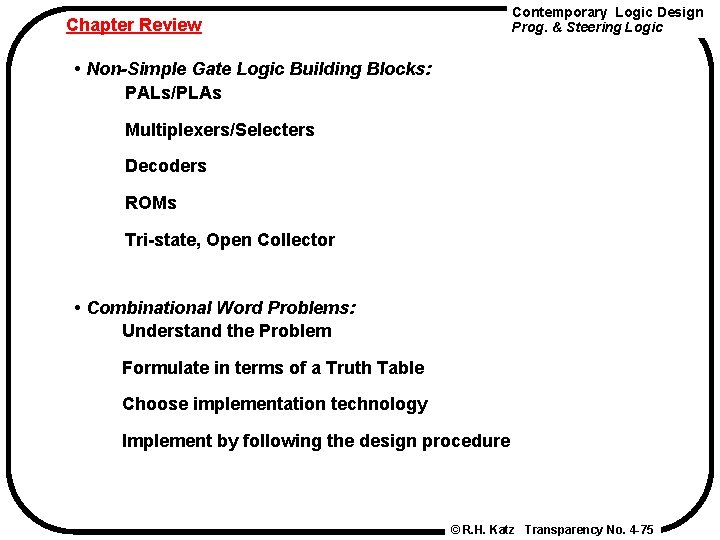
Contemporary Logic Design Prog. & Steering Logic Chapter Review • Non-Simple Gate Logic Building Blocks: PALs/PLAs Multiplexers/Selecters Decoders ROMs Tri-state, Open Collector • Combinational Word Problems: Understand the Problem Formulate in terms of a Truth Table Choose implementation technology Implement by following the design procedure © R. H. Katz Transparency No. 4 -75