CONSTRUCTION OF BULDINGS Dr Odey Alshboul Buildings Is

CONSTRUCTION OF BULDINGS Dr. Odey Alshboul

Buildings : Is a set of mainly gravity loads of different components of the • structure with out neglecting other types of force. *types of buildings : 1. Bearing walls 2. Beam – column 3. Combination

1. Bearing wall : Properties : • 1. load mode : slab>wall>foundation • 2. high cost. • 3. high durability • 4. high dead load. • 5. high cost • 6. a lot time and work • 7. Limited for small number of stories • building.

Some illustrations for bearing wall : Before concrete molding After

2. Beam – column : Properties: 1. Load mode : slab>beam>column>foundation 2. Low cost. 3. Low dead load. 4. Low durability. Note : the column and the beam are preferred to be constructed at the same time.

Beam – columns types : Skelton: small distance with low loads Fixed: big distance with high loads

3. Combination : *Combines bearing wall + column beam system. *commonly used in the stair.

Factor of safety : There are many equations , the use of each equations varies • according to the location of the building and the natural conditions in the surrounding area. Factor of safety equation in Jordan : • Wu=1. 2 x(Dead load) + 1. 6 x (live load ) •

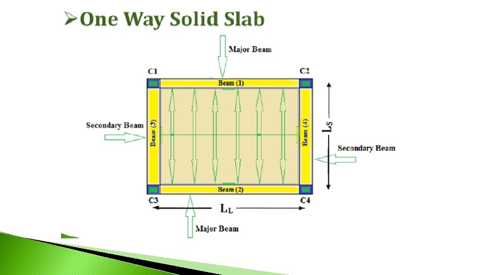
Definition of slab �Slab: is a structural member whose thickness is small compared to its length and width. �Slab could be: reinforced concrete slab, timber slab or steel slab. �Slabs are usually used in floors and roofs construction.

Classification of slabs �According to transferred loads form slab to supporting beams and columns, slabs are classified to two types: 1. One way slab. 2. Two way slab.

Classification of slabs �According to the shape, slabs are classified to: 1. Flat slab 2. Inclined (Roof) 3. Dome

Classification of slabs �Reinforced concrete slabs are classified to main two types: 1. Solid Slab 2. Hollow Slab

Solid Slab �Solid slab contains totally concrete and steel. �Thickness of solid slab is a bout 12 -15 cm. �Solid slab could be: one way slab or two way slab.

Solid Slab

Solid Slab �Disadvantages of solid slab: 1. High deflection and moment. 2. High own weight of slab with increasing the thickness of slab which cause heavy load from slab. 3. Heat and sound isolation are almost zero. 4. Not good for high rise building because of high dead load according to high own weight.

Hollow Slab 1. Ribbed Slab 2. Waffle Slab

Hollow Slab : Ribbed Slab One way Ribbed Slab Two way Space is filled with hollow block made from: concrete, clay or P. V. C. Top matt and rib are reinforced concrete members. Thickness of top matt is not standard or designed, it is within range (5 -9 cm). Thickness of rib equals thickness of hollow block. Main reinforcement is placed in rib, and the steel in top matt is shrinkage and temp. reinforcement.

Hollow Slab : Ribbed Slab �Hollow Block in Jordan: Length = 40 cm. Width = 20 cm. Thickness = 18, 24, … cm

Hollow Slab : Ribbed Slab �One way ribbed slab: Ribs are constructed in one direction (short direction).

Hollow Slab : Ribbed Slab �One Way Ribbed Slab:

Hollow Slab : Ribbed Slab �One Way Ribbed Slab:

Hollow Slab : Ribbed Slab �One Way Ribbed Slab:

Hollow Slab : Ribbed Slab �Two Way Ribbed Slab:

Hollow Slab : Ribbed Slab �Two Way Ribbed Slab:

Hollow Slab : Ribbed Slab �Two Way Ribbed Slab:

Hollow Slab : Waffle Slab �This type of slabs is two way hollow slab and used for big places for spans (9 – 30 m). � For space, using special molds from metal or polystyrene.

Hollow Slab : Waffle Slab �Waffle slab is suitable for airports, library and any other bid place because of high absorption of sound.

Hollow Slab : Waffle Slab

Flat Slab �Flat slab is a slab with constant thickness and it supports on columns directly. �This type of slabs are used for industrial places or large stories. �Advantages: 1. 2. 3. Simplified formwork. Better lighting Saving in clear light of the story and uniform surface for suspended sprinkles and head crane rails.

Flat Slab Solid slab Ribbed slab

Flat Slab

Flat Slab

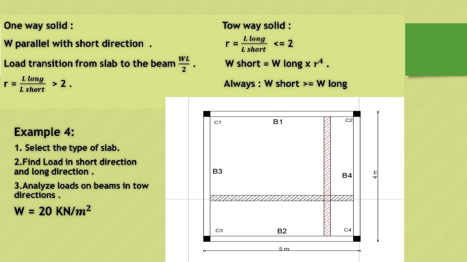
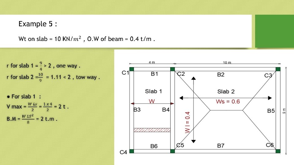
Solid slab : *Consisting of reinforced concrete. *of their disadvantages it possesses a high dead load. *tow way or one way depend on this equations : R= Ll/Ls. If (R>2) , so its one way. If (R<=2) , so its tow way.

Example 1 : Select the types of slabs in this plane.
 = 1 <=2 • Slab")
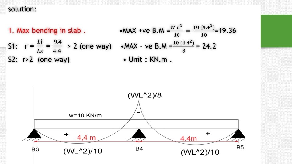
Solution : Slab 1 : r= LL/LS = (3/3) = 1 <=2 • Slab 1 > two way. • Slab 2 : r=(6/3)=2<=2 : two way • Slab 3 : r=3/2 =1. 5 <=2 : two way • Slab 4 : r=6/2=3>2 : one way • Note : steel bars diameters Ø 8, Ø 10, Ø 12, Ø 14 , 16 , 18 , 20.

For one way solid slab: r LL Ls 2 Max deflection for simply supported 5 w. L span with uniform load: max 384 EI If we take strip in short direction and another strip in long direction. m a x( s h o r t ) m a x( lo n g ) 5 ws Ls 4 384 EI 5 w L L 4 L 384 EI w s L 4 L w 4 w. L Ls s w. L L 4 s

For one way solid slab the total load transfer from slab to beams in one direction which is short direction. Example: for solid slab 15 m*5 m, determine the load in short direction: 4 L 4 s 4 L 15 w. L 4 w s w. L L 5 ws 81 w. L In one way solid slab the load transfer always in short direction : w ws

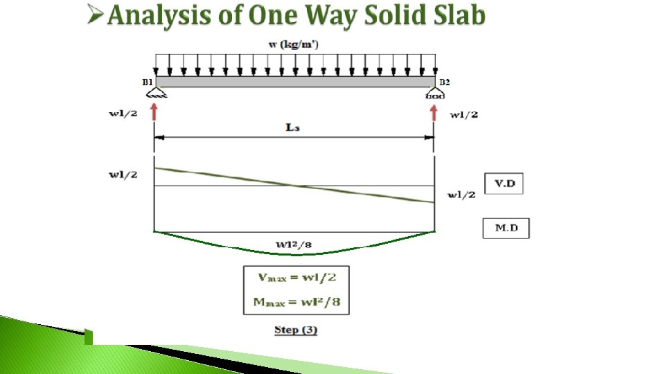
r LL Ls 1. 2. 3. 2 one way solid slab w ws Slab’s Analysis procedure: Take a strip with (1 m) width parallel to short direction. Confirm total load on slab (w) (load/area) to distributed load (load/m’): Load/m’= (load/m²) * (1 m) Determine the max. shear and max. moment for simply supported span with distributed.

Beam’s Analysis procedure: ** Analysis of major beams: w. Ls. LL 2 LL 1. Load /m’ from slab on beam 1, beam 2 = 2. Total load on beam 1, beam 2 = own weight of beam+ load from slab. 3. Determine max. shear and max moment: w. L 2 2 w. L M max 8 where : w total load L length of beam Vmax

Beam’s Analysis procedure: ** Analysis of secondary beams: 1. Total load on beam 3, beam 4 = own weight of beam 2. Determine max. shear and max moment: w. L 2 2 w. L M max 8 where : w total load L length of beam Vmax

1. 2. 3. 4. Example: For shown solid slab, load on floor w = 20 (k. N/m²), own weight for each beam = 5 (k. N/m’), determine: Max. shear and max. moment in the slab. Max. shear and max. moment in B 1. Max. shear and max. moment in B 4. Total axial load on C 2

Solution: r= 10/4 = 2. 5 >2 → one way solid slab w s w 2 0 k N / m 2 : load transfer parallel to short direction. 1. Max. shear and max. moment in the slab. Vmax M max w. L 20 * 4 40 k. N 2 2 w. L 20* 4 40 k. N. m 8 8

Solution: 2. Max. shear and max. moment in B 1. w. L s L L Load from slab on Beam (1)= 2 L L 20 * 4 *10 40 k. N / m 2 *10 Total load on Beam (1) = 40 + 5 = 45 k. N/m’. w. L 45 *10 225 k. N 2 2 w. L 45*10 562. 5 k. N. m 8 8 Vmax M max

Solution: 3. Max. shear and max. moment in B 4. Total load on Beam (4) = 5 k. N/m’. w. L 5 * 4 10 k. N 2 2 w. L 5* 4 10 k. N. m 8 8 Vmax M max 4. Total axial load on C 2 = load from B 1 + load from B 4 Total axial load on C 2 = 225 + 10 = 235 k. N.

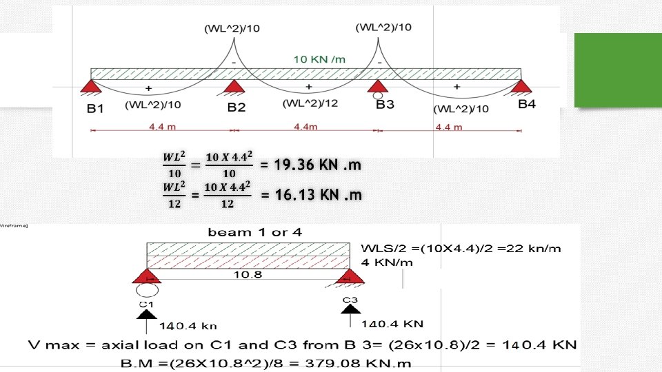
Continuous beam :

Equations to help you to solve problems without structure analysis.

Equations :

For two way solid slab: r LL 2 Ls For two-way solid slab: load transfer from slab to beams in two directions. All beams in two way solid slab are major beams.

Rankine – Grashoff theory *we often use in two way case. We take a point in the center to make it easier. At the center of the slab : SL = S S

Rankine – Grashoff theory :
 • Load on short")
Rankine – Grashoff theory : • Load in long (Wl) • Load on short (Ws) •

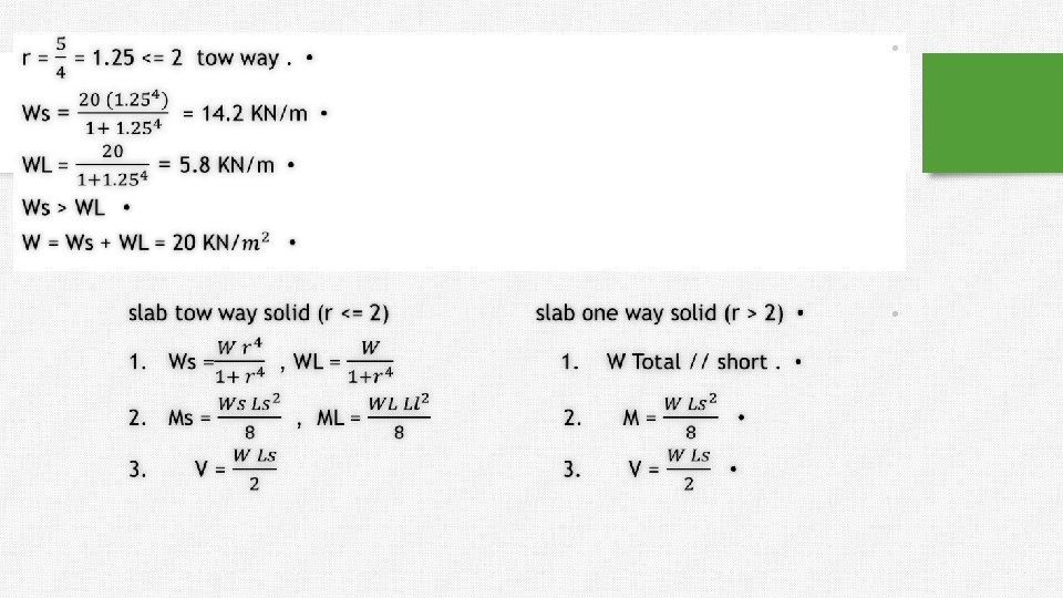
4 ws L L r 4 w. L L 4 s w s w L r 4. . (1) w w s w L. . . . (2) substitute eqn(1) in eqn(2) w w r 4 w w w (1 r 4 ) L L L w w. L 1 r 4 ws 1 r 4
 width")
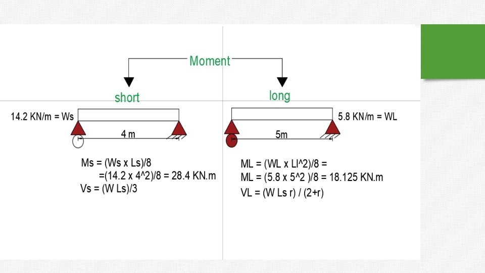
1. 2. 3. Slab’s Analysis procedure: Take a strip with (1 m) width parallel to short direction or parallel to long direction. Confirm total load on slab (w) (load/area) to distributed load (load/m’): Load/m’= (load/m²) * (1 m). Determine the max. shear and max. moment for simply supported span with distributed. **Short direction : Vmax w. L s s , M max s s 2 8 2 **Long direction : Vmax w L L L , M max L L 2 8 2
 = 20 k.")
Example: For shown solid slab with load on floor (w) = 20 k. N/m². Determine max. shear and max. moment in slab. 10 1. 25 2 Two waysoildslab 8 wr 4 20 *1. 25 4 2 14. 2(k. N / m ) w. S 1 r 4 1 1. 254 w 20 5. 8(k. N / m 2 ) w. L 4 4 1 r 1 1. 25 r Short Direction : w. L 14. 2* 8 Vmax 56. 8 k. N 2 2 2 M max 2 w. L 14. 2 *8 113. 6 k. N. m 8 8 Long Direction : Vmax w. L 5. 8 *10 29 k. N 2 2 w. L 2 5. 8 *10 2 72. 5 k. N. m M max 8 8

• • Beam’s Analysis procedure: All beams are major beams with different load. Loads transfer from slab to beams as two triangles and two trapezoids.
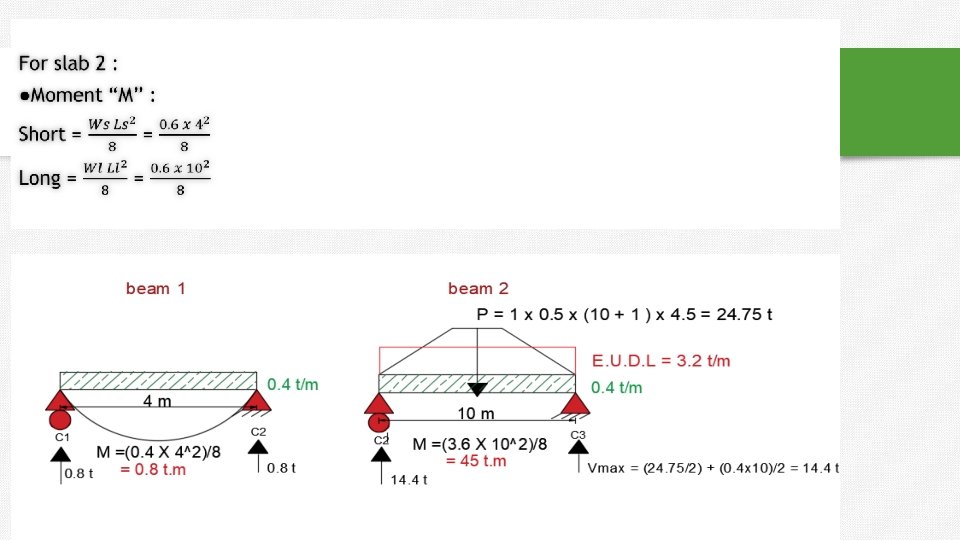
 + Beam (2): (o. w)LL w *")
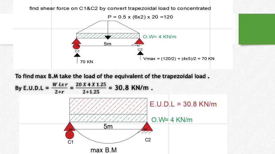
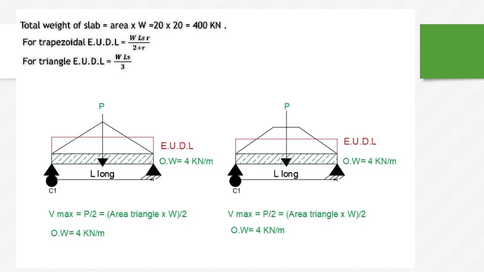
Beam’s Analysis procedure: ** Beam (1) + Beam (2): (o. w)LL w * Area of Trapezoid 2 2 2 L this formula is applicable just for uniform distributed load (o. w + E. U. D. L )* 8 Vmax Mmax For bending moment calculations only : **For Trapezoid Equivalent Uniform Distributed load (E. U. D. L) w. LS r 2 r
 + Beam (4): Vmax (o. w)Ls w")
Beam’s Analysis procedure: ** Beam (3) + Beam (4): Vmax (o. w)Ls w * Area of Triangle 2 2 For bending moment calculations only : **For Triangle Equivalent Uniform Distributed load (E. U. D. L) w. LS 3

Example 2 : One way solid slab. 1. Max bending moment in the slabs 2. (B 4 , B 1 ) , calculate shear and moment. O. W = 4 KN/m
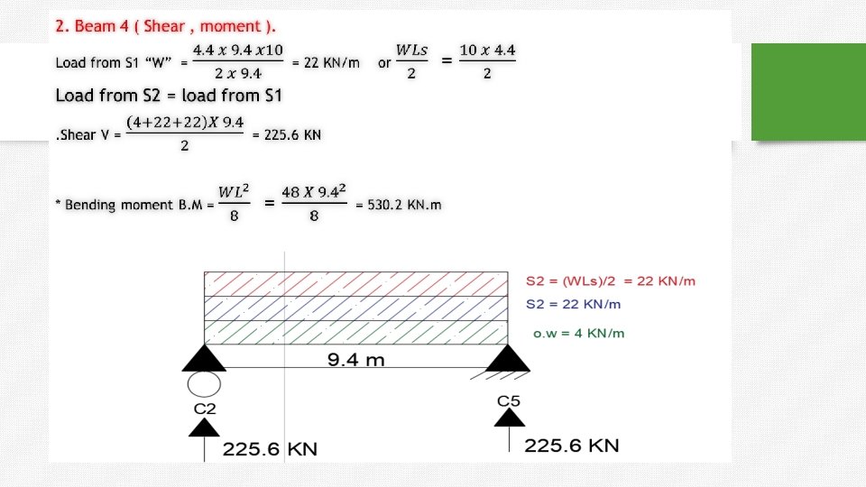
. =225. 5 +")
shear in column 2 from three beams (B 1+B 2+B 3). =225. 5 + 8. 8 = 243 KN.

Girder : What is Girder? Girder is basically a beam which supports other smaller beams and acts as the main horizontal support of a structure. Unlike beams, girders are designed to support major concentrated loads such as columns or beam reactions and their load bearing capacity is much greater than beams. It can be made from a variety of construction materials such as concrete, stainless steel, or a combination of both. It supports vertical loads and may consist of a single piece or more than one piece bound together.

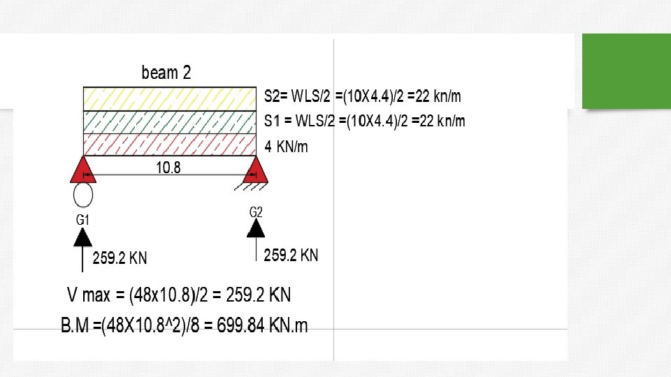
Example 3 :
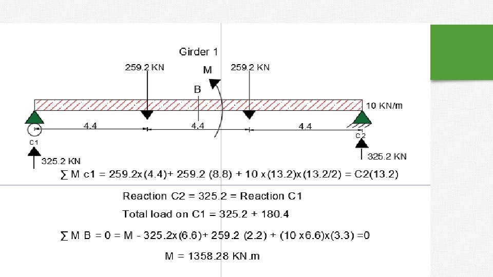

Continue to Example 4 :
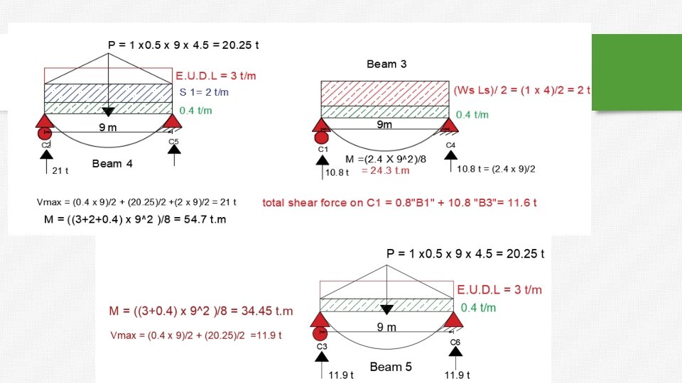
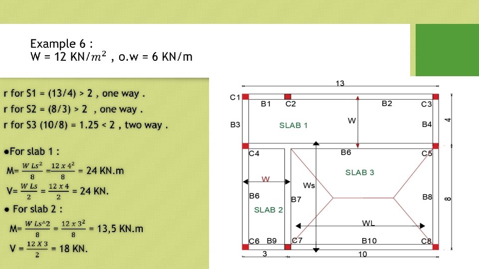
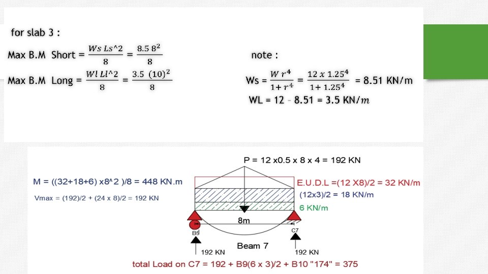
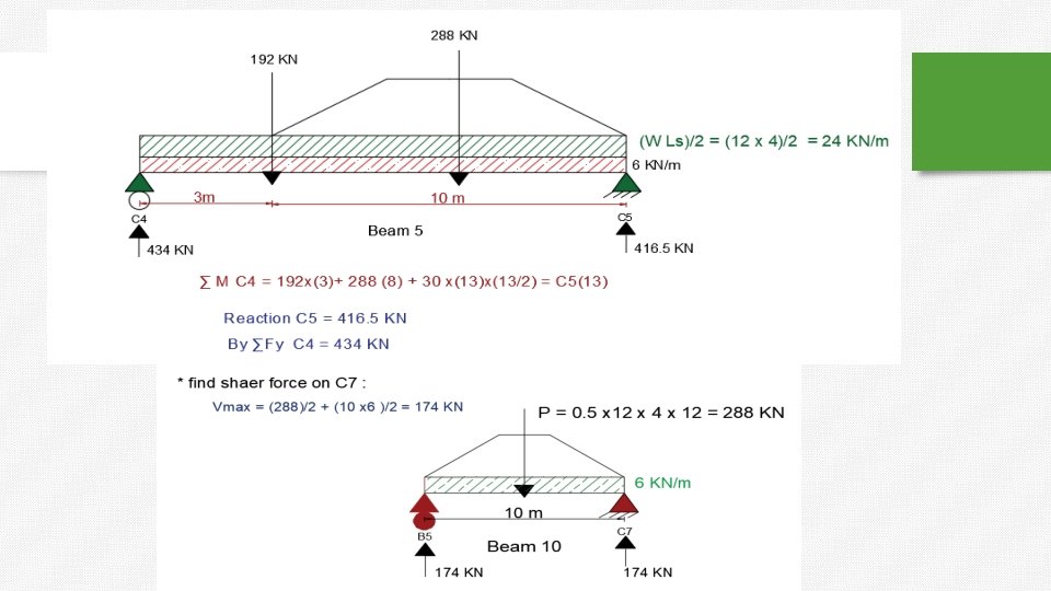

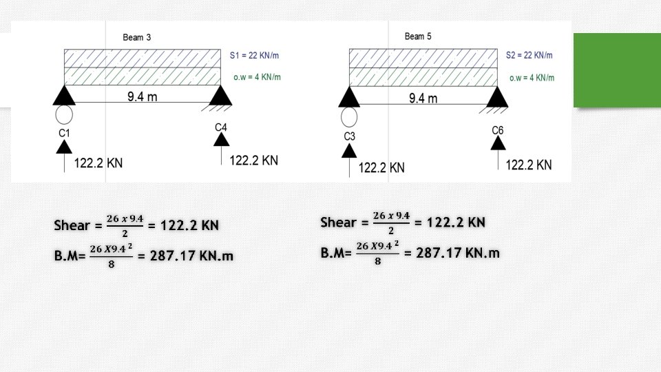
How to find max moment in beam 5:
:")
Hollow slab (one way ):

Dimensions vary depending on the code that we use. Hollow block dimension = Width (40 , 36 , …) x 20 x thickness (18 , 25 , …. . )

One Way Ribbed Slab

Analysis of One Way Ribbed Slab • • • Area supported by one rib = (Ls) (s) Load for each rib = (Ls) (w) Load / m. R for each rib = Ls * w Ls = ws

Analysis of One Way Ribbed Slab �Example: For shown ribbed slab, if load on floor on slab = 18 (k. N/m²). Determine max shear and max moment in each rib. Soln: - s = 40+12= 52 cm = 0. 52 m - Load/m. R for each rib = w*s = 18*0. 52 = 9. 36 (k. N/m) w. L 9. 36 * 5 23. 4 k. N 2 2 w. L 9. 36 * 5 29. 25 k. N. m 8 8 Vmax M max

Analysis of One Way Ribbed Slab �In one way ribbed slab, the load transfer from slab to beams with same procedure in one way solid slab.

Analysis of One Way Ribbed Slab �Example: For shown ribbed slab, if load on floor on slab = 18 (k. N/m²) , own weight for each beam = 4 (k. N/m). Determine: 1. Max shear and max moment in B(1). 2. Max shear and max moment in B(3). 3. Total axial load on C 1

Analysis of One Way Ribbed Slab � Solution: 1. Max shear and max moment in B(1). Load from slab on Beam (1)= w. Ls LL 18 * 5 * 8 45 k. N / m 2*8 2 LL Total load on Beam (1) = 45 + 4 = 49 k. N/m’. w. L 49 * 8 196 k. N 2 2 w. L 49 *8 392 k. N. m 8 8 V max M max

Analysis of One Way Ribbed Slab � Solution: 2. Max shear and max moment in B(3). Total load on Beam (3) = 4 k. N/m’. w. L 4 * 5 10 k. N 2 2 w. L 4*5 12. 5 k. N. m 8 8 Vmax M max 3. Total axial load on C 1. - Total axial load on C 1 = 10 + 196 = 206 k. N. - Total axial load on C 1 = (1/4) load of slab + (1/2) load of beam = 0. 25*(18*5*8) + 0. 5*(4*5) = 206 k. N.

Solution :

Example • • C 5 C 6 2 W slab = 20 KN/m. O. Wt of beams = 5 KN/m. Width of rib = 12 cm. Length of block = 40 cm. 10 m C 1 For panel 1 r = 5 = 1. 25<2 4 Two way. Ls/2 4 m Ls/2 P C 3 5 m C 4 4 m

1. Find the axial load on C 6. (

Solution •

2. Max moment in S 1 : 4 Short direction : ws = w r 0= 14. 2 KN/m. 4 1+r 2 BM max = 14. 2 *4 = 28. 4 KN. m 8 Long direction : wl = w – ws = 20 -14. 2 = 5. 8 KN/m 2 BM max = 5. 8 *5 = 18. 125 KN. m 8 3. Max shear in S 2 : load on each rib = 20 *0. 52 =10. 4 KN/m. V max = 10. 4 *4 = 20. 8 KN 2

Two Way Ribbed Slab �For two way solid slab: load transfer from slab to beams in two directions. �All beams in two way solid slab are major beams

Two Way Ribbed Slab w w. L 1 r 4 ws 1 r 4 * * Load / m. R of short rib w s * B *1 * * Load / m. R of long rib w L * B *1
")
Two Way Ribbed Slab �Example: For shown ribbed slab with load on floor (w) = 20 k. N/m², O. W for each beam = 5 k. N/m. Mold = 65⨯ 65 cm. Rib width = 10 cm. Determine: 1. Max. shear and max. moment in slab. 2. Max moment in Beam (1). 3. Total axial load on C 2. 15 1. 25 12 4 4 wr 20 *1. 25 2 14. 2(k. N / m ) w. S 4 4 1 r 1 1. 25 w 20 2 5. 8(k. N / m ) w. L 4 4 1 r 1 1. 25 r * * Load / m. R of short rib 14. 2 * 0. 75 *1 10. 65 k. N/m * * Load / m. R of long rib 5. 8 * 0. 75 *1 4. 35 k. N/m
: 1. Max. shear and max. moment in slab.")
Two Way Ribbed Slab �Example (continue): 1. Max. shear and max. moment in slab. * *Short Direction : V max w. L 10. 65 *12 63. 9 k. N 2 2 w. L 10. 65 *12 191. 7 k. N. m M max 8 8 **Long Direction : Vmax M max w. L 4. 35 *15 32. 625 k. N 2 2 w. L 4. 35 *15 122. 34 k. N. m 8 8
: 2. Max moment in Beam (1). w. L")
Two Way Ribbed Slab �Example (continue): 2. Max moment in Beam (1). w. L S r 20 *12 *1. 25 92. 3 k. N / m 2 1. 25 * Total Load 5 92. 3 97. 3 k. N/m w. L 2 * Mmax 97. 3 *15 2 2736. 56 k. N m 8 8 * E. U. D. L 3. Total axial load on C 2. Total load on C 2 = ¼ load of slab + ½ load of beam = ¼ *(20*12*15) + ½ *(5*12) = 967. 5 k. N.

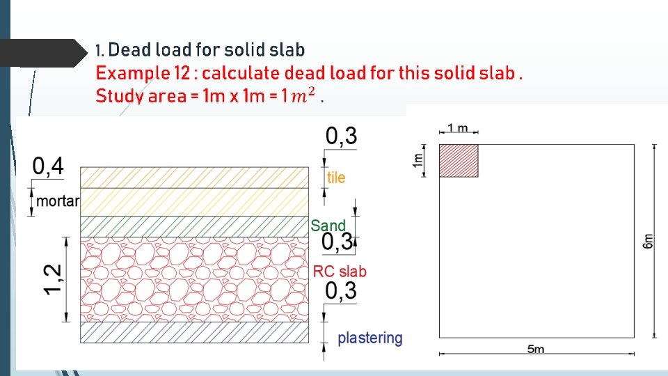
Calculation of Dead load

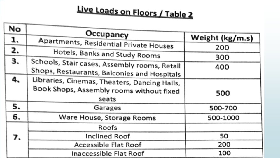
Ldesign = wu = 1. 2 D +1. 6 L + 0. 5 (Lroof or S) Dead load: Live load: depends on type of structure. own weight of slab + weight of finishing + weight of partitions + another sustained load. **Example: live load for private house = 200 kg/m 2 live load for school = 400 kg/m 2 Intensity of load for slab = force/area = kg/m 2 = k. N/m 2 =lb/ft 2.

Solution :

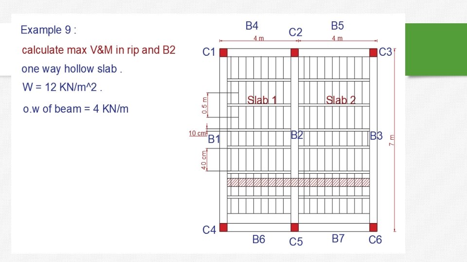
2. Hollow slab one way. Example 13 :
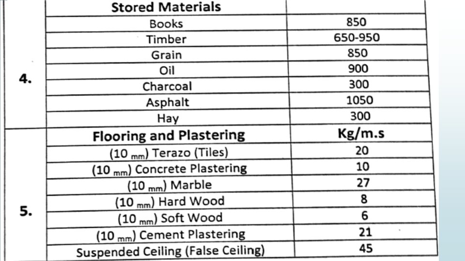
 : 1. Plastering : 1 cm 21 kg/m 3")
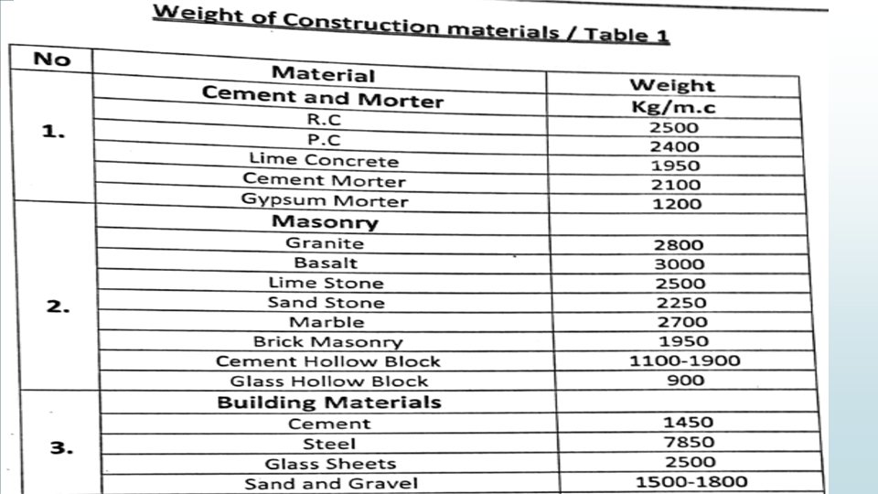
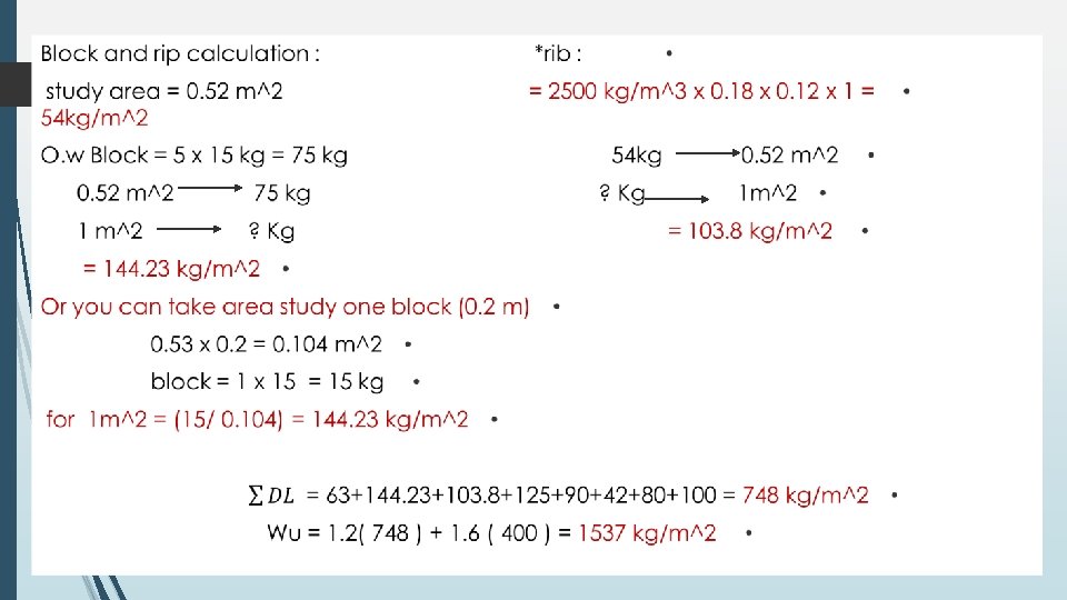
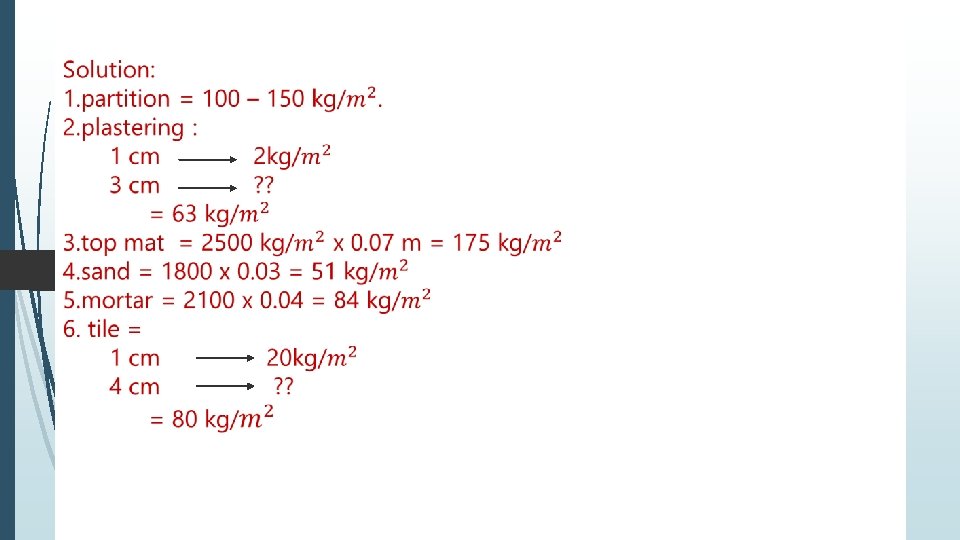
Dead Load ( 1 m^2) : 1. Plastering : 1 cm 21 kg/m 3 cm ? 2. Top mat : 2500 kg/m^3 x 0. 05 m = 125 kg/m^2. 3. Sand : 1800 x 0. 05 =90 kg/m^2. 4. Mortar : 2100 x 0. 02 = 42 kg/m^2. 5. Tile : 1 cm 20 kg/m^2 4 cm ? 6. Partition : =100 kg/m^2

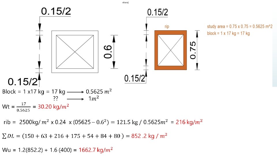
3. Dead load for hollow tow way slab. Example 15 : H. B = 60 X 24 cm.

Good luck " The end "
- Slides: 116