Construct a controller of the process shown in
")

 All outputs off 0 1 S, TM, H start 0")


:")


- Slides: 10
Construct a controller of the process shown in figure below. The timer output (TU) is initially low when its input (TM) is low. When TM is taken high the output stays low for five minutes and then goes high. It resets to low when TM is taken low. All level sensors become true when the level is reached. The process sequence is: 1. Fill the tank to level A (LA) from valve A (VA) 2. Fill the tank to level B (LB) from valve B (VB) 3. Start the timer (TM), stir (S), and heater (H) 4. When five minutes are up take stir (S) and heater (H) off 5. Open output valve (VC) until the tank is empty (LE) 6. Take the timer low (TM) and go to step 1.
Solution; To provide the solution, we first form the state variable representation of the system by assignment of binary states. There are four input variables (LA, LB, LE, TU) and six output variables (VA, VB, VC, TM, S, H). A discrete state of the system is defined by specifying these variables. Because each variable is a two-state variable, we use a binary representation: true=1 and false=0. Thus, for input, if level A has not been reached, then , LA=0 and if it has been reached, then LA=1. Also, for output, if valve C is to be closed, then we take VC=0, and if it is commanded to be open, then VC=1. Let us take the binary “word” describing the state of the system to be defined by bits in the order Process outputs (Controller inputs): (LA)(LB)(LE) (TU) Process inputs (Controller outputs): (VA)(VB)(VC)(TM)(S)(H)
Initial Condition (Stand By) All outputs off 0 1 S, TM, H start 0 1 LU VA 1 VC 0 LA 1 LE 1 VB 0 0 LB 1
6 0 1 Start 0 1 2 3 6 X 1 4 MUX 5 6 S 0 S 1 3 2 x 1 MUX 1 S C A R 3 Control Memory (ROM) 8 X 15 3 NXTADD 1 3 NXTADD 0 3 Control Outputs SEL
Control Signals • Six control signals needed. • We can use these signals as is or encode them to reduce the number of bits needed in the control word. • If we do not encode these: 6 bits needed 5 4 3 2 1 0 (VA)(VB)(VC)(TM)(S)(H) VA: 100000 VB: 010000 VC: 001000 TM: 000100 S : 000010 H : 000001
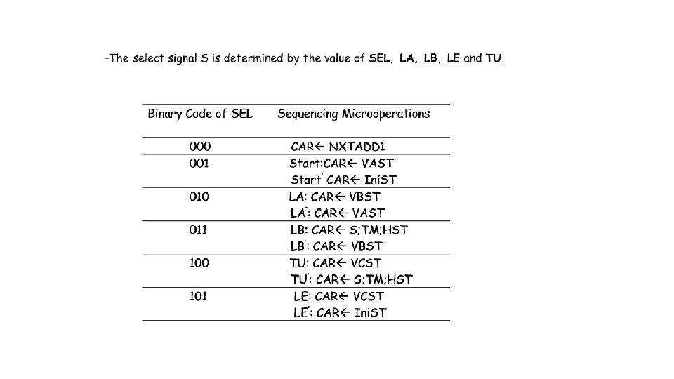
-Register Transfer Description of the Microprogram Each memory location contains a microinstruction, to be executed in the corresponding state. The register transfer statements are:
The above Register Transfer Operation can be translated into a symbolic microprogram (control words): Example: Address Ini. ST: can be written as: Address Ini. ST: Start: CAR VAST, Start’ CAR Ini. ST
Symbolic Microprogram: Address NXTADD 1 NXTADD 0 SEL CONTROL Ini. ST VAST Ini. ST Start none VAST VBST VAST LA VA VBST S; TM; HST VBST LB VB S; TM; HST VCST S; TM; HST TU S, TM, H VCST Ini. ST LE VC
Binary Microprogram