
Consolidation of ISOLDE Scanners Redesign for HRS GPS

- Slides: 39
Consolidation of ISOLDE Scanners Redesign for HRS & GPS Ana Mi arna u Ma rin William Andrea zza Gerrit Jan Fo cker BE-BI Technical Boa rd 3 r d May 2018
Outline • Overview: current situation • Motivation for consolidation • Proposed designs • Specific components • Advantages, Summary and Outlook 2
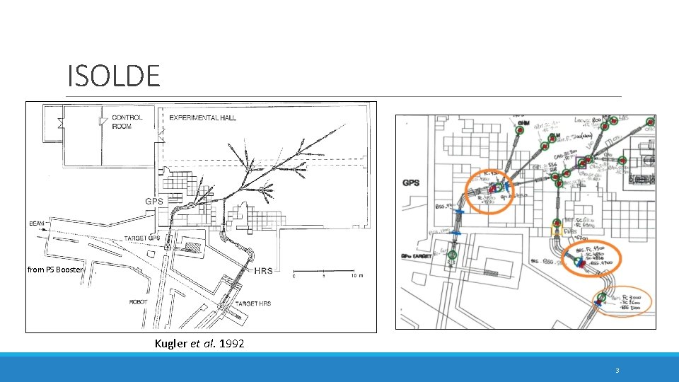
ISOLDE from PS Booster Kugler et al. 1992 3
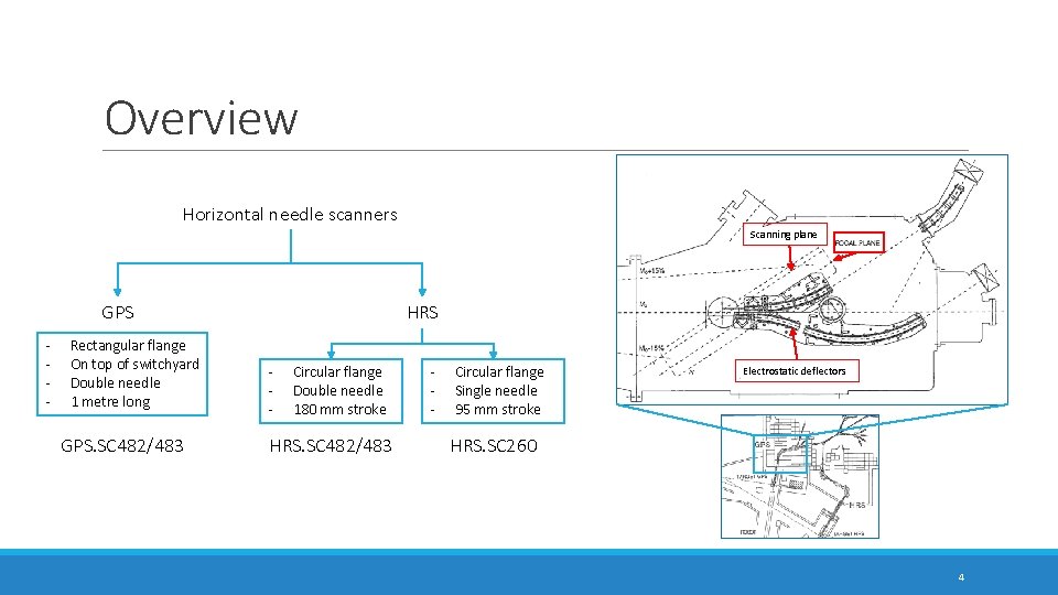
Overview Horizontal needle scanners Scanning plane GPS - Rectangular flange On top of switchyard Double needle 1 metre long GPS. SC 482/483 HRS - Circular flange Double needle 180 mm stroke HRS. SC 482/483 - Circular flange Single needle 95 mm stroke Electrostatic deflectors HRS. SC 260 4
Needle scanners • Beam profile measurements • Signal is proportional to number of particles in beam • Needle • Ø 0. 5 mm tube • Phynox: flexible stainless steel, Co-Cr-Ni alloy 5
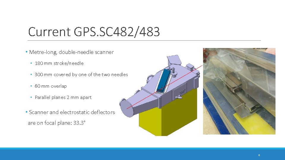
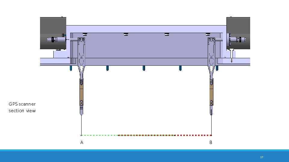
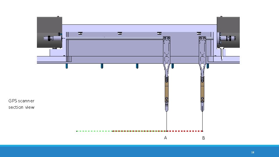
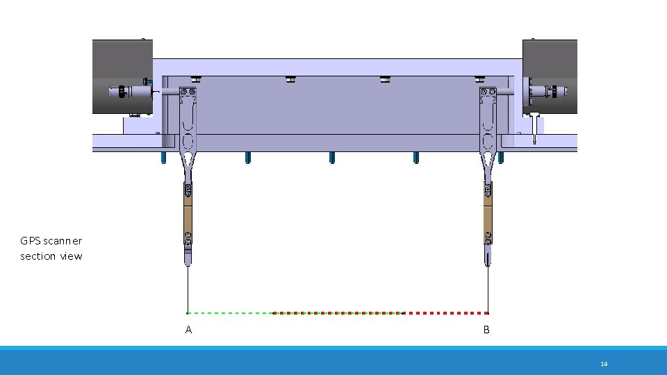
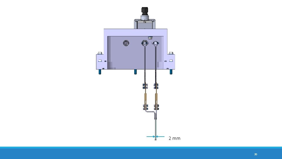
Current GPS. SC 482/483 • Metre-long, double-needle scanner • 180 mm stroke/needle • 300 mm covered by one of the two needles • 60 mm overlap • Parallel planes 2 mm apart • Scanner and electrostatic deflectors are on focal plane: 33. 3° 6
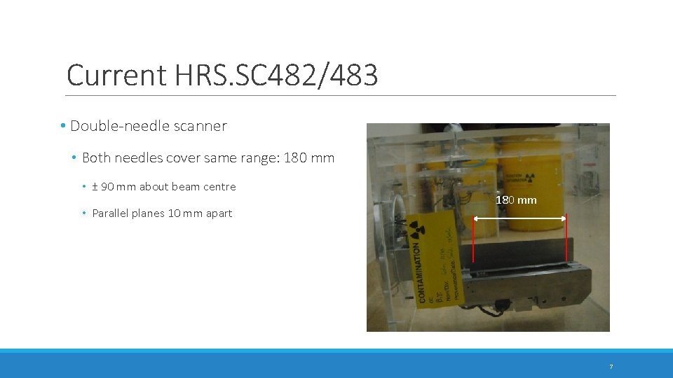
Current HRS. SC 482/483 • Double-needle scanner • Both needles cover same range: 180 mm • ± 90 mm about beam centre • Parallel planes 10 mm apart 180 mm 7
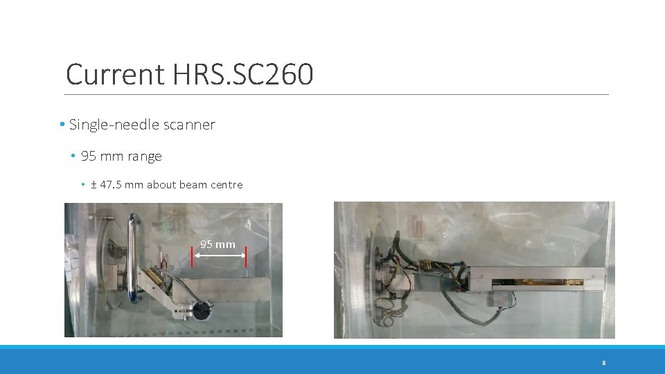
Current HRS. SC 260 • Single-needle scanner • 95 mm range • ± 47. 5 mm about beam centre 95 mm 8
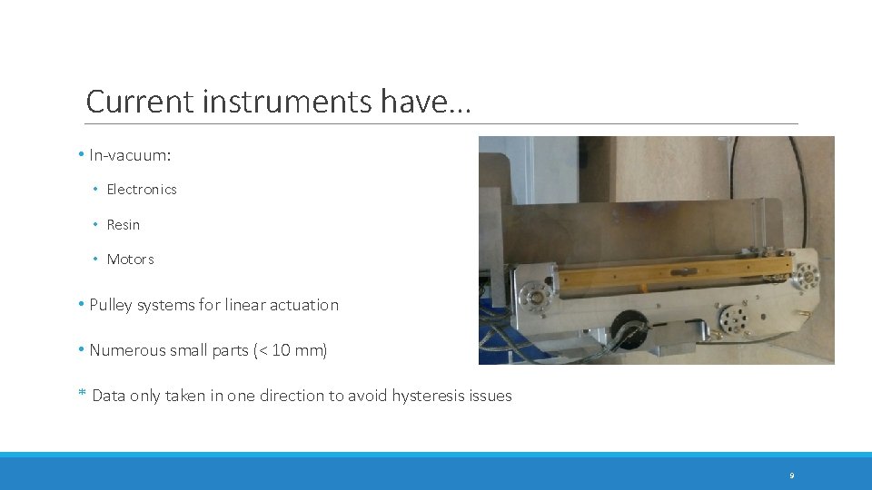
Current instruments have… • In-vacuum: • Electronics • Resin • Motors • Pulley systems for linear actuation • Numerous small parts (< 10 mm) * Data only taken in one direction to avoid hysteresis issues 9
Motivation for Consolidation • All of this makes for frequent and costly maintenance • Exposure to radioactivity: irradiation and contamination • Instruments have been running for +20 years • Were designed for few thousand scans Aim: • Simplify mechanisms in use • Improve reliability • Minimise required maintenance 10
Requirements and Constraints • Keep needles in the current position * Kick-off meeting Nov. 2017: * Extension of GPS Scanner range would be welcome * If possible, bring needles in HRS double scanner closer together • Keep or minimise footprint • Vacuum level -> 10 -6 mbar • Radiation -> Irradiation and contamination hazard 11
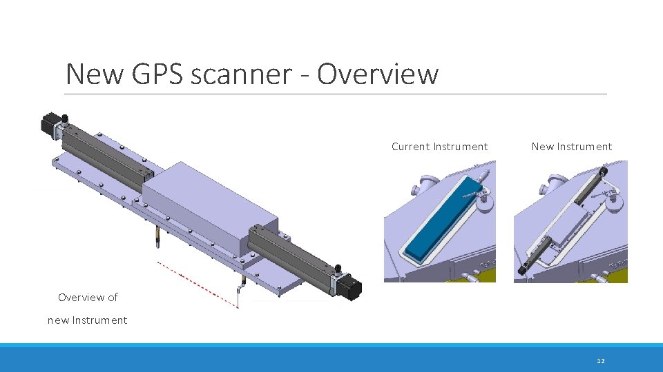
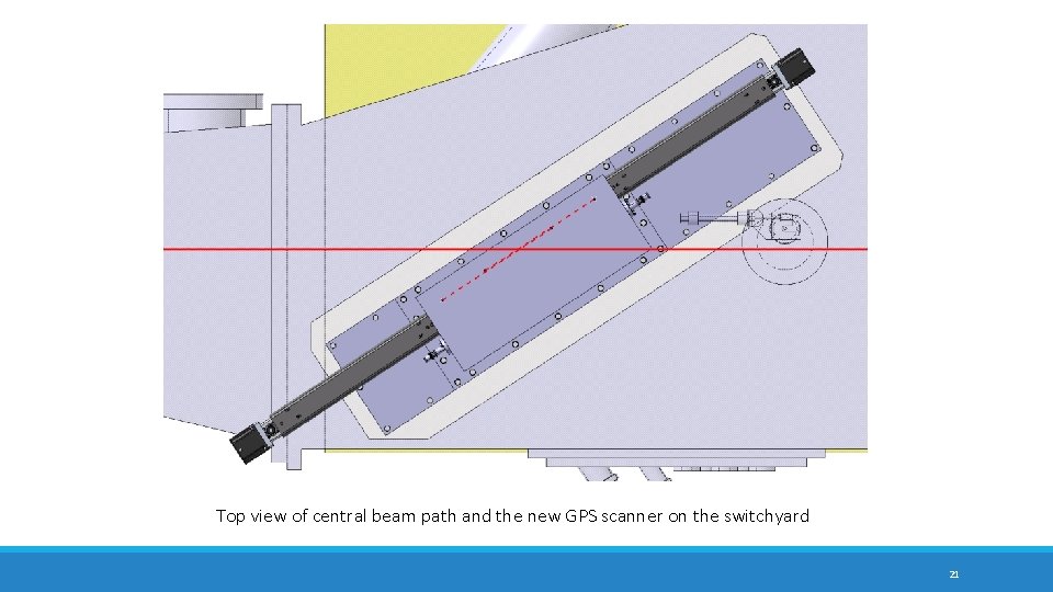
New GPS scanner - Overview Current Instrument New Instrument Overview of new Instrument 12
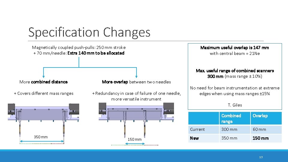
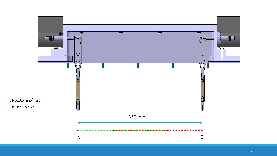
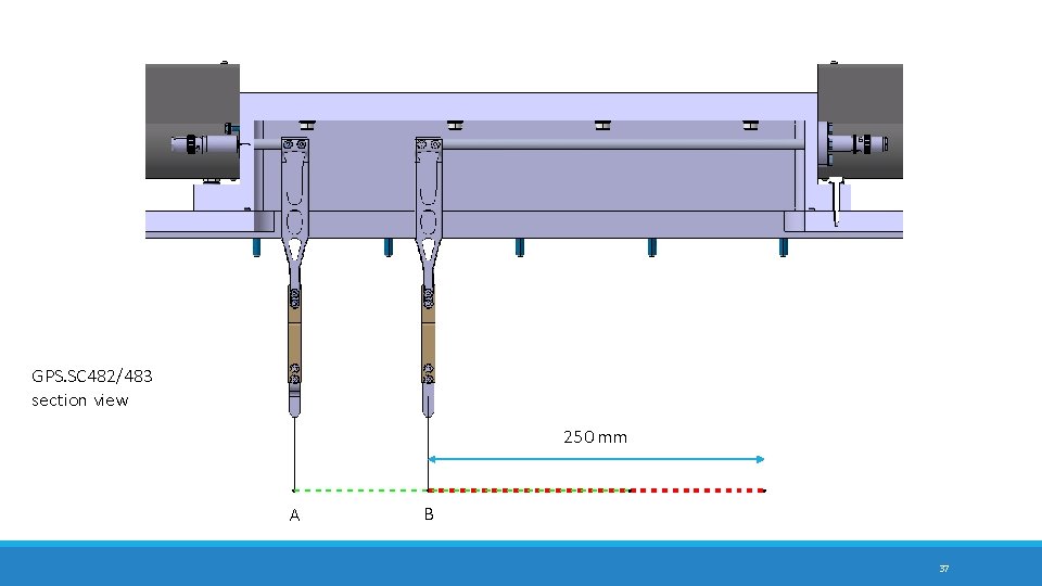
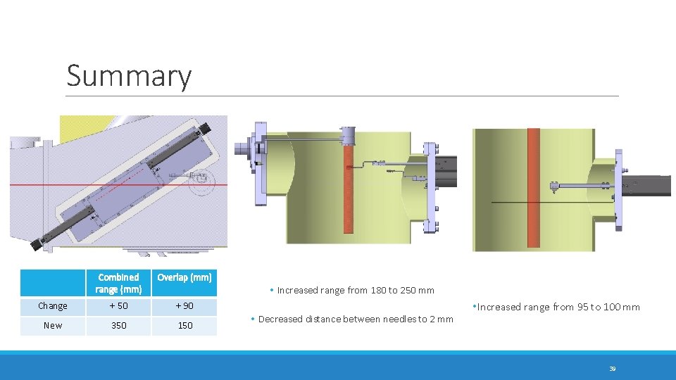
Specification Changes Magnetically coupled push-pulls: 250 mm stroke + 70 mm/needle: Extra 140 mm to be allocated More combined distance + Covers different mass ranges Maximum useful overlap is 147 mm with central beam = 21 Ne More overlap between two needles + Redundancy in case of failure of one needle, more versatile instrument Max. useful range of combined scanners 300 mm (mass range ± 10%) No need for beam instrumentation at extreme edges when using mass ranges ± 15% T. Giles 350 mm 150 mm Combined range Overlap Current 300 mm 60 mm New 350 mm 13
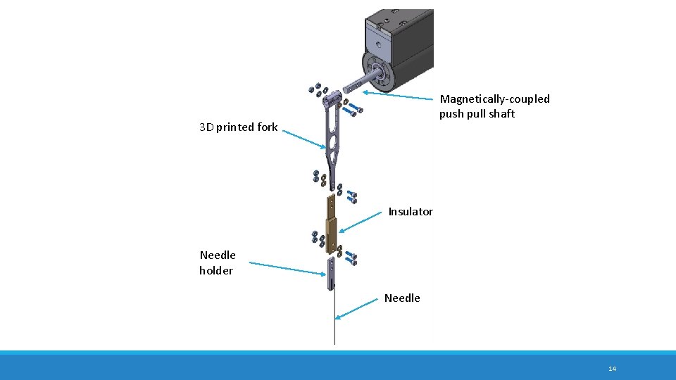
Magnetically-coupled push pull shaft 3 D printed fork Insulator Needle holder Needle 14
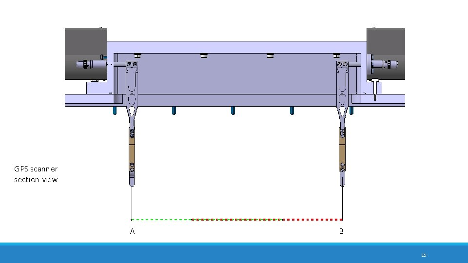
GPS scanner section view A B 15
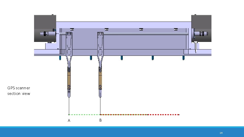
GPS scanner section view A B 16
GPS scanner section view A B 17
GPS scanner section view A B 18
GPS scanner section view A B 19
2 mm 20
Top view of central beam path and the new GPS scanner on the switchyard 21
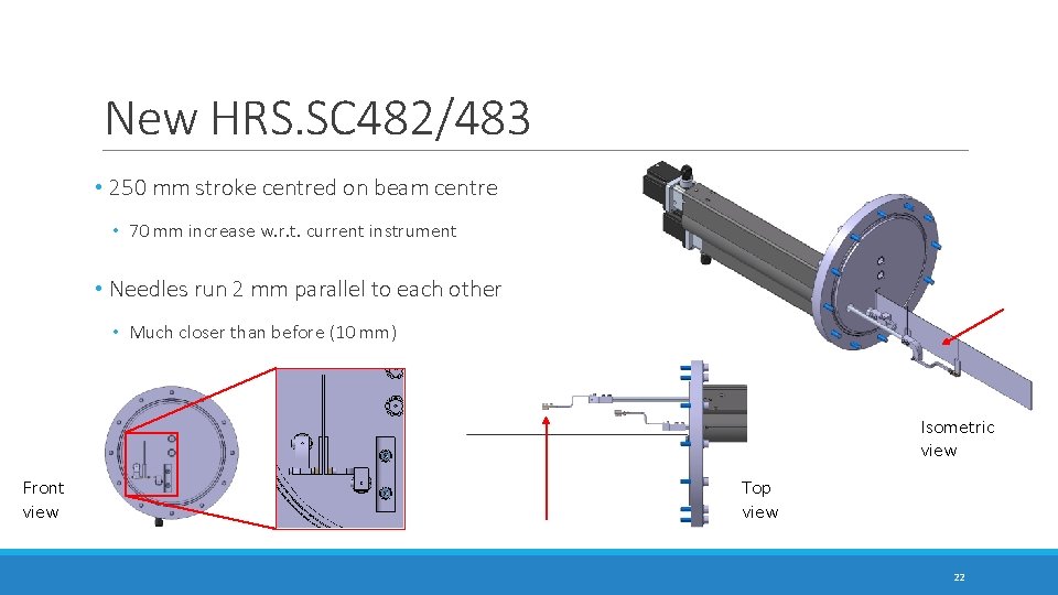
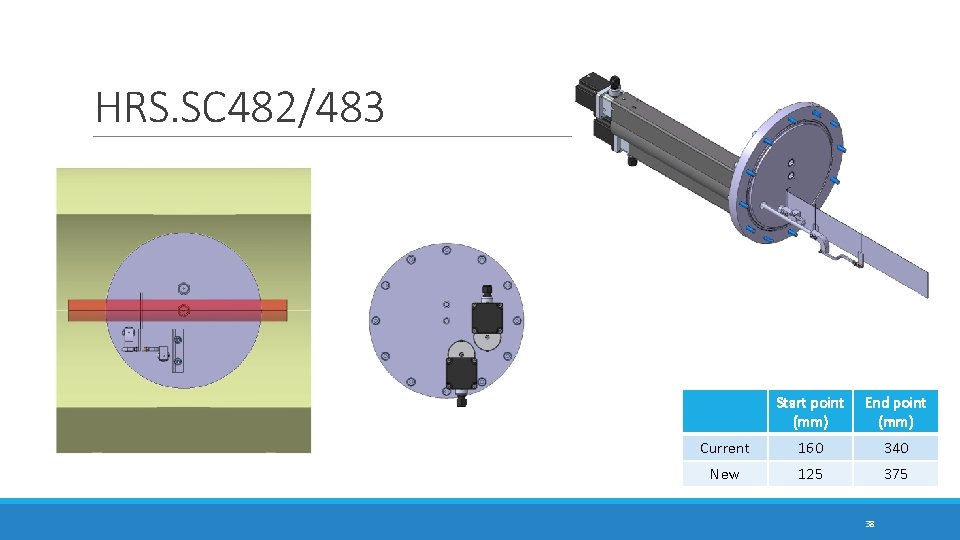
New HRS. SC 482/483 • 250 mm stroke centred on beam centre • 70 mm increase w. r. t. current instrument • Needles run 2 mm parallel to each other • Much closer than before (10 mm) Isometric view Front view Top view 22
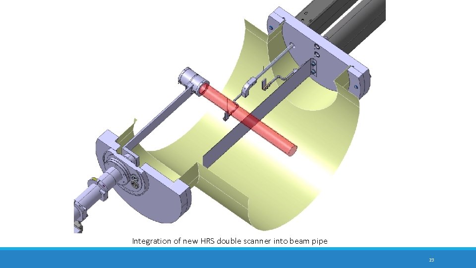
Integration of new HRS double scanner into beam pipe 23
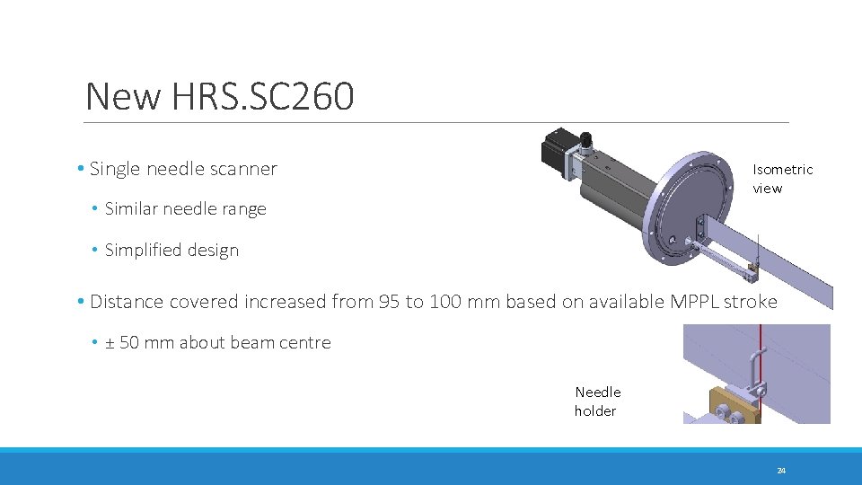
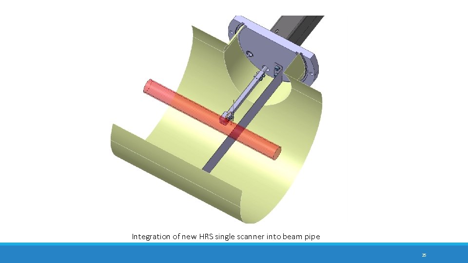
New HRS. SC 260 • Single needle scanner Isometric view • Similar needle range • Simplified design • Distance covered increased from 95 to 100 mm based on available MPPL stroke • ± 50 mm about beam centre Needle holder 24
Integration of new HRS single scanner into beam pipe 25
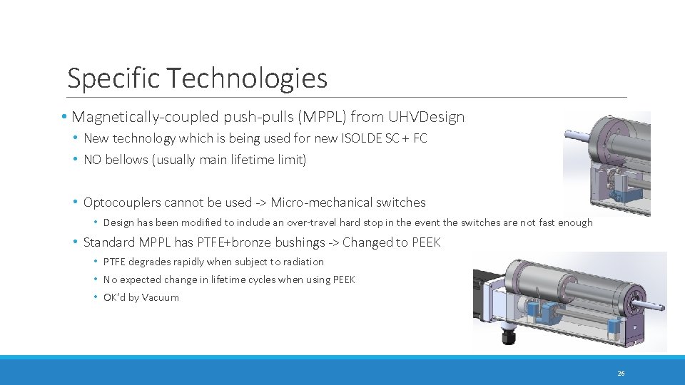
Specific Technologies • Magnetically-coupled push-pulls (MPPL) from UHVDesign • New technology which is being used for new ISOLDE SC + FC • NO bellows (usually main lifetime limit) • Optocouplers cannot be used -> Micro-mechanical switches • Design has been modified to include an over-travel hard stop in the event the switches are not fast enough • Standard MPPL has PTFE+bronze bushings -> Changed to PEEK • PTFE degrades rapidly when subject to radiation • No expected change in lifetime cycles when using PEEK • OK’d by Vacuum 26
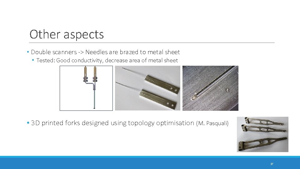
Other aspects • Double scanners -> Needles are brazed to metal sheet • Tested: Good conductivity, decrease area of metal sheet • 3 D printed forks designed using topology optimisation (M. Pasquali) 27
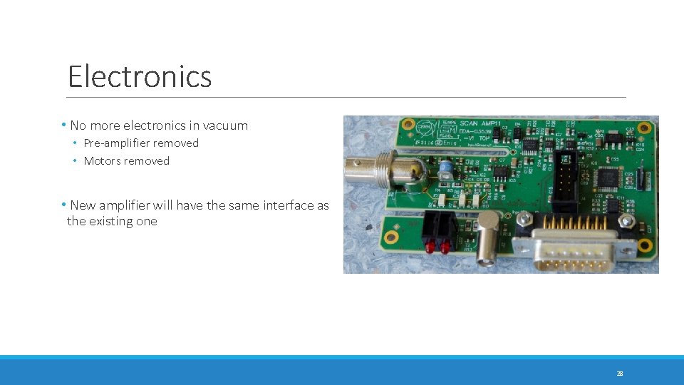
Electronics • No more electronics in vacuum • Pre-amplifier removed • Motors removed • New amplifier will have the same interface as the existing one 28
Advantages • Improved reliability and maintenance • Simplified design • Fewer and newer parts • No pulleys nor bellows • Improved vacuum quality • Elimination of electronics, resin, motors, pre-amplifier in vacuum • Use of magnetically-coupled push-pulls with CF flanges • Instrument improvement means we could change software to take data in both directions 29
Summary • Consolidation project in which specification is kept or improved as requested • Improvement in reliability • Decrease and simplification of maintenance required • ALARA: reduced work time in very harsh environment • Spare parts and manpower reduced • Improved operation: instrument availability 30
Outlook • Design approval • Manufacturing June-September 2018 • Assembly – Late 2018 • Installation – LS 2 31
Special thanks to Tim Giles, Ray Veness, Paulo Martins, Federico Roncarolo, Michel Duraffourg, Matthieu Deschamps, Alexandre Dorsival, Michele Pasquali, Romain Gerard Questions? 32
Back-up slides 33
Phynox tube needles • Austenitic Cobalt-based alloy • 40% Co, 20% Cr, 16% Ni • High strength and high ductility • Age-hardenable • Excellent corrosion resistance, non-magnetic, used over wide range of temps. • Elastic modulus: 200 GPa 34
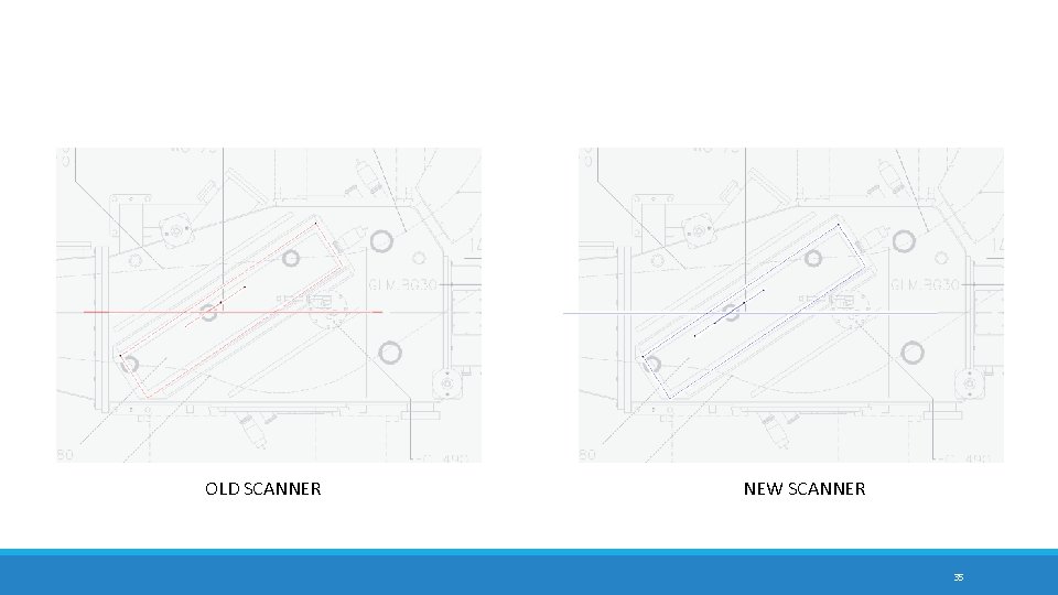
OLD SCANNER NEW SCANNER 35
GPS. SC 482/483 section view 350 mm A B 36
GPS. SC 482/483 section view 250 mm A B 37
HRS. SC 482/483 Start point (mm) End point (mm) Current 160 340 New 125 375 38
Summary Combined range (mm) Overlap (mm) Change + 50 + 90 New 350 150 • Increased range from 180 to 250 mm • Decreased distance between needles to 2 mm • Increased range from 95 to 100 mm 39