Connections SERIAL DATA Serial Terminals Serial connections n


 ¨ Send n n")


 side “opposite” definitions than the switch")


- Slides: 19
Connections
SERIAL DATA
Serial Terminals
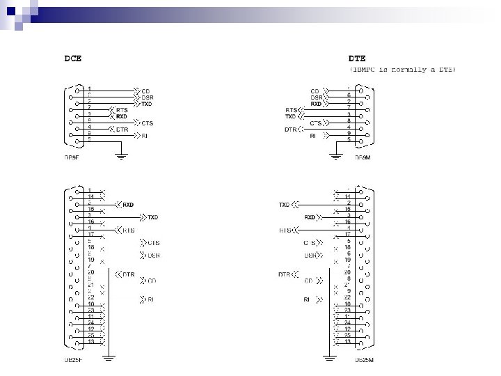
Serial connections n Telecommunication History 101 ¨ RS-232 n DTE – Data Terminal Equipment ¨ ¨ n DCE – Data Communications Equipment ¨ n n Teletype Computer Modems Send Receive
Computer to Computer? n What if equipment close by? ¨ Direct n DTE-DTE Conflict of signals! ¨ Receive to receive ¨ Send to send - !!!! n Solution: ¨ Use a “null” modem
Configuration n Must configure to connect: ¨ Correct Speed n 110, 300, 1200, 2400, 4800, 9600, etc. ¨ Number of bits n 7 or 8 ¨ Parity n None, even, odd, mark, space ¨ Stop bits n 1 or 2 n Most modern devices default: ¨ 9600 -8 -n-1
ETHERNET
Ethernet
Ethernet n n Standard cable and jack RJ-45 (8 pins) ¨ Send n n on 1 -2 + P 1 - P 2 ¨ Receive n n + P 3 - P 6 on 3 -6
Ethernet + Power n Power over Ethernet ¨ Add power to the spare wires
EIA/TIA 568 A and B n 568 A WIRING STANDARD n 568 B WIRING STANDARD PIN WIRE COLOR 1 White w/Green Stripe 1 White w/Orange Stripe 2 Green w/White Stripe 2 Orange w/White Stripe 3 White w/Orange Stripe 3 White w/Green Stripe 4 Blue w/White Stripe 5 White w/Blue Stripe 6 Orange w/White Stripe 6 Green w/White Stripe 7 White w/Brown Stripe 8 Brown w/White Stripe Note: Only pairs 2 and 3 are used for Standard Ethernet wiring. Pairs 1 and 4 can be used for other purposes such as telephones or even a second separate, complete Ethernet connection.
EIA/TIA Cable pairings
Two Ethernets over one cable Pin No. conductor color Name 1 white and orange TX_D 1+ 2 orange TX_D 1 - 3 white and green RX_D 2+ 4 blue BI_D 3+ ** 5 white and blue BI_D 3 - ** 6 green RX_D 2 - 7 white and brown BI_D 4+ ** 8 brown BI_D 4 - ** Use pairs 1 and 4 for the second Ethernet connection
Ethernet Wiring Conventions n Note: ¨ PC (NIC) side “opposite” definitions than the switch or router side ¨ Colors may change
“typical” connection Networking Device No problem! PC PC
PC to PC? n Big problem! PC 1 ¨ PC 1 Receive connected to PC 2 Receive n Bigger problem! ¨ PC 1 Transmit connected to PC 2 Transmit! PC 2
PC to PC Solution n Crossover cable
Auto Sense n Some devices “auto sense” and set up the proper connections