Cone Beam Computed Tomography CBCT Dr Hussein Ahmed
 Dr. Hussein Ahmed Hassan")
Cone Beam Computed Tomography (CBCT) Dr. Hussein Ahmed Hassan

Conventional Dental X-Rays Imaging

Extra oral Anatomical landmarks on a non-collimated cephalometric radiograph of an 11 -year-old boy

Cephalometric • Cephalometric analysis depends on cephalometric radiography to study relationships between bony and soft tissue landmarks and can be used to diagnose facial growth abnormalities prior to treatment, in the middle of treatment to evaluate progress or at the conclusion of treatment to ascertain that the goals of treatment have been met. • A Cephalometric radiograph is a radiograph of the head taken in a Cephalometer (Cephalostat) that is a head-holding device.

Oblique Lateral Radiograph

The Direct System • The direct system works with a solid state sensor. • The word direct refers to the digital image that is produced directly, without extra work. • There exist two types of sensors used in a solid state or direct system. • The most widely used is the charge coupled device (CCD). • A second system recently developed is called the complmentry metal- oxide semiconductor (CMOS) sensor system • The primary difference with the CMOS sensor is that the electronic components are integrated inside the electronic chip instead of having a scintillation layer like the CCD sensor.

Panoramic X-Rays-Tomography

Panoramic x-rays are examples of tomography. • X-rays are the simplest form of tomogram in medicine, because they do not include volumetric or 3 -D information. • X-rays produce a two dimensional image of a single slice along the mandibular arch. • The x-ray beam is fan shaped, with the fan unfolded in the vertical dimension. • The beam projects through a vertical slit close to the patient as the machine slowly revolves around his or head. • The beam and the x- ray revolve around the patient's head in the same direction (clockwise when viewed from the top), • While the cassette moves in the opposite direction. • The images produced show the bony structures closest to the film cassette.

Positioning for orthopantomography

So, the reasons the contralateral structures show faintly or not at all on film are: 1. They appear very enlarged, blurry and dim. 2. They are made dimmer, because shadows these objects cast spend less time falling on the receptor. 3. Shadows of the contralateral objects are blurred by their greater velocity.

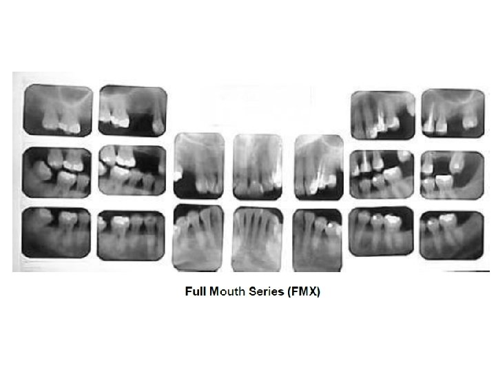
Intraoral Film Placement Techniques 1. Periapical radiographs help diagnose issues with teeth, bone, the lamina dura, and periodontal ligament. 2. Bitewing radiographs diagnose problems with crowns and interproximal areas. Decay, calculus, overhanging margins 3. Occlusal films are used to diagnose disorders of the jaw or palate.

Intraoral Radiography

The standard occlusal technique illustrated (yellow line represents the occlusal plane, the red arrow the Xray beam aimed through the bridge of the nose at a 65° angle with the occlusal plane).

Dental Radiography Digital Radiology Systems

Indirect systems • Indirect digital radiology uses a traditionally exposed film a flat bed or slide scanner to copy images into a JPG or TIFF file that is stored in the computer. • Clinicians can take pictures of traditional films with a digital camera and transfer images into digital format. • Software from copies images using a scanner and automatically arranges them in proper orientation and order. • These images can be manipulated, rotated, and enhanced. Zoom, contrast, and brightness

The semi direct system • The semi direct system is similar to the indirect system in that stored images are scanned into the computer. • The semi direct method uses a photo stimulable phosphor (PSP) • Phosphor plates temporarily store images until they are transferred into a computer. • Special packets are used to hold phosphor plates. These look similar to traditional films. • Semi direct systems are more comfortable for patients than digital sensors used in the direct technique, because they are thinner. • The scanner transfers images into patients’ computerized charts
 radiographic")
Limitations of the conventional radiographic images • In dentistry, conventional two-dimensional (2 -D) radiographic imaging has been widely used. • However, the conventional radiographic images have limitations like 1. inherent magnification, 2. distortion, 3. superimposition of structures, and 4. lack of depth for three-dimensional anatomical objects.

CT How CT Scanners See a Slice The x-ray source projects a thin, fan shaped beam through the slice the clinician wants to image. The line detector is situated opposite the detector on the other side of the subject. The x-ray source and the detector are mounted on the gantry opposite one another as they both revolve around the subject

limitations of CTs in Dental imaging • They are expensive and require a lot of space. • The 3 D reconstruction is time consuming and so less cost efficient. • Furthermore the radiation exposure to the patient has limited their usage to complex craniofacial problems and for specialized diagnostic information only.
 • CBCT is specifically designed to produce 3 D")
Cone Beam Computed Tomography (CBCT) • CBCT is specifically designed to produce 3 D images of the maxillofacial region. • Produces images with isotropic submillimeter spatial resolution, has the potential to reduce the size and cost of CT scanners. • When combined with application-specific software tools, CBCT can provide dentomaxillofacial practitioners with a complete solution for performing specific diagnostic and surgical tasks, such as dental implant planning. • The other terms used: 1. Cone beam volumetric imaging (CBVI) 2. Cone beam volumetric tomography (CBVT).

Picture of currently available CBCT scanner
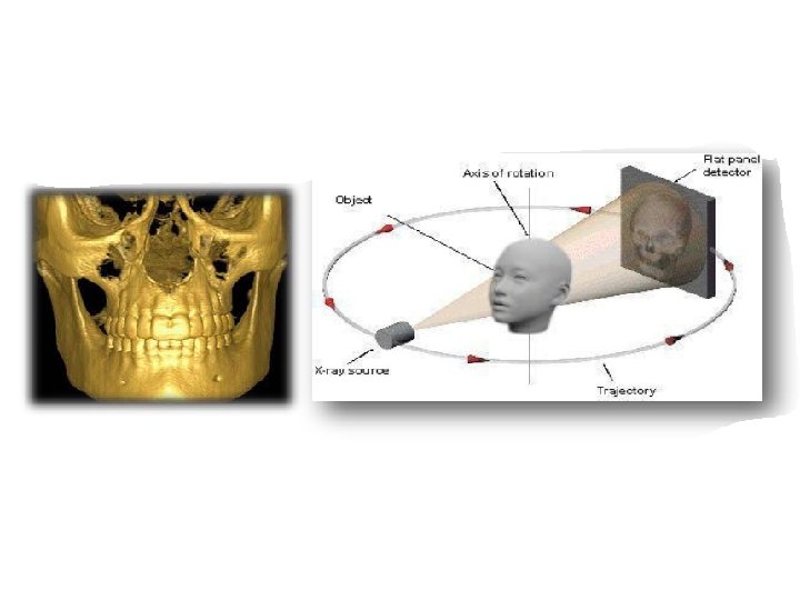
 is a diagrammatic representation of a typical construct in a CBCT system. (B)")
(A) is a diagrammatic representation of a typical construct in a CBCT system. (B) is a diagram showing the difference in X-ray geometry of CBCT and conventional CT.

Acquisition of CBCT Volume • CBCT devices consist of X-ray source (cone shaped divergent beam) and a 2 -D image detector. • The X-ray source and the image detector are connected by an arm that rotates around the patient’s head during the scan. • Rotation varies from 180° to 360°. • Typically, the volumetric data is captured with single rotation around the patient’s head as the transmitted beam of radiation is aimed at the image detector. • Beam collimators either match the size of the detector and the beam size or can be used to further reduce or collimate the field of view.

the volumetric data is captured with single rotation around the patient’s head as the transmitted beam of radiation is aimed at the image detector.

Acquisition of CBCT Volume –con-- • With most CBCT units, a series of 2 -D raw base images or projections are captured. • The number of raw images varies from 180 to 600 or up to 1000 in some machines. • Exposure times vary from 6 s to 40 s. Many machines have pulsating radiation, which helps reduce the patient dose. • The ranges for tube current (m. A) and peak voltage (k. Vp) are 1– 15 m. A and 85– 120 Kv, respectively. • After processing axial, coronal, and sagittal planes, images appear on the computer monitor as an Explore screen

Explore screen from a CBCT machine with large field of view is shown. This is a typical image display in coronal, sagittal, and axial planes

Detectors Used in CBCT Units • The detector converts the incoming remnant X-ray photons from the patient into electrical signals. • Later computer processing converts these signals into visible images. • CBCT machines are equipped with either 1. Image intensifier tubes/charge-coupled device (II-CCD) or 2. A flat-panel detector (FPD). • II-CCD units are usually bulkier as compared to the FPD. • FPD is made up of scintillation crystal screen on a matrix of photodiodes embedded in a solid-state amorphous silicon layer with thin-film transistors. • The advantages of FPD include higher radiosensitivity, lesser radiation exposure, and better image quality.
 • FOV is the anatomical volume that can be captured")
Field of View (FOV) • FOV is the anatomical volume that can be captured by the detector. FOV varies in size. • Machines with larger detectors offer larger FOV, with ability to collimate the X-ray beam to a small area or FOV. • With collimation of the X-ray beam, the FOV can be reduced to suit the needs, and this reduces the amount of exposure to the patient and improves image quality. • Multiple FOV options, ranging from few centimeters to full head size, are available for various clinical scenarios.

Reconstruction Process of CBCT Images • A volumetric data set is created with the individual basic frames by a series of algorithms or reconstruction process at the processing computer or the workstation. • Both computers are connected via an Ethernet connection for transfer of the acquired individual frames from acquisition computer to the workstation for processing. • For image display, the CBCT units also use HU units. However, in CBCT, the measured density numbers correspond to the grayscale values and do not directly represent HU units
 Hard tissue renderings from CBCT data are shown. (b) Example of another type")
(a) Hard tissue renderings from CBCT data are shown. (b) Example of another type of rendering with soft tissue is shown

Display of CBCT Images • The operator can change slice thickness. generate, lateral cephalometric images. • The CBCT data can be displayed in various formats such as volume rendering and maximum intensity projection (MIP). • In a MIP, only the highest voxel value is displayed within the selected thickness in area of interest. • The contrast and brightness can be easily adjusted to improve the display. • Segmentation of an area of interest is a very useful tool when separation of certain structures is desired from the volume for in-depth analysis.
 Enhanced depth 3 -D model. (b) Enhanced depth with soft tissue")
(a) Enhanced depth 3 -D model. (b) Enhanced depth with soft tissue

Virtual cephalometric image from a CBCT unit
 and cross sectional images (b) from CBCT data showing the")
Reconstructed panoramic image (a) and cross sectional images (b) from CBCT data showing the relationships of the forming tooth with the surrounding structures

CBCT maxillary images produced for dental implant treatment planning with an opaque radiographic marker in the left posterior maxilla. (a) Reconstructed panoramic image. (b) Cross-sectional images. Pneumatization of the maxillary sinus is also visible in the region of interest.

Factors Influencing Image Quality in CBCT • CBCT machines use a single 2 -D image detector with a cone-shaped beam, scatter is more seen with CBCT as compared to medical CT scanners • Good spatial resolution attains by smaller voxel size. However, this requires higher exposure • The contrast resolution decrease by image noise, scatter, larger fields of view, reduced milliamperes, and kilovoltage settings of the X-ray generator.

Picture of currently available Pro. Max 3 D CBCT scanner

Import DICOM file and Crop image

Note histogram at right side outlined in red

- Slides: 43