Concrete Inspection Construction Inspection for Field Office Activities


 • Temperature changes can cause –")
 • Steel bars used for contraction reinforcement are usually")


")


 • Rolls – Difficult to flatten and position correctly –")


 • Minimum cover shown on drawings: ± 3/8” • Location in")
 • Minimum spacing shown on drawings: ± 1/4” • Uniform spacing")


 1. 2. 3.")
- Slides: 47
Concrete Inspection Construction Inspection for Field Office Activities
Objectives • Review and define terms related to quality concrete • Review typical specification requirements • Discuss testing procedures and results based on specification
Terms Related to Quality Concrete • Durability – Long lasting • Permeability – Ability to hold fluids • Water to cement ratio (w: c) – Affects durability and permeability – Low w: c results in higher durability and lower permeability (Good) – Determined from weight of total water in the mix (includes water in aggregates) divided by total weight of cement-like material (cement and fly ash)
Terms Related to Quality Concrete • Slump – Measure of workability • Air – Amount of entrained air in mix • Compressive Strength – Strength of design mix or actual specimens after 28 -day curing period • Curing – Time period when exposed concrete surfaces are not allowed to be dry
Concrete Specifications and Testing Review the concrete specification in the Mortality Facility Example Plans • Compressive Strength – 4000 psi at 28 days • Water to cement ratio – 0. 50 • Air Content – 5 -8 percent • Slump – 3 -5 inches • Curing – 7 days without drying • Temperature – 40 -90 degrees F What testing is required?
Concrete Class Problem Found in Class Problems Section. Refer to Happy Hogmeister Mortality Facility Design packet to answer questions 1 -4 at your tables. The specification in the mortality facility example requires a w: c of 0. 50 or less. 1. Does the design mix meet the specification?
Concrete Class Problem 2. What is w: c of batch? Weight of water = 242 gal x 8. 33 lb/gal = 2024 lbs Weight of cement = 5076 w: c = 2024/5076 = 0. 399 3. Can water be added? 4. If water is added how many revs required?
Concrete Class Problem 3. How many gallons of water can be added? Max water weight = 0. 45 x 5076 = 2284 lbs Max water gallons = 2284/8. 33 = 274 gallons Additional gallons = 274 -242 = 32 gallons
Steel Reinforcement for Concrete Construction Inspection for Field Office Activities
Objectives - Develop an Understanding Of: • • The purpose and use of steel reinforcement The materials used for steel reinforcement The placing of steel reinforcement The tolerances for placement of steel reinf
Basic Principals • Concrete is strong in compression and shear strength • Concrete is weak in tensile strength Compressive strength 4000 psi Shear strength @ 80% ~ 3200 psi Tensile strength @ 10% ~ 400 psi
• Steel is strong in compressive, tensile and shear strength • Structural grade steel: – Tensile strength ~ 18, 000 psi – Compressive strength ~ 90, 000 psi • Steel bars in compression tend to buckle • Will not support substantial compressive loads alone
• Concrete bonds well with steel • Both have nearly the same coefficient of expansion – 1 inch per 100 feet between winter and summer • Concrete and steel stick together and act, together, to make reinforced concrete • R/C is strong in both: – Compression, and – Tension
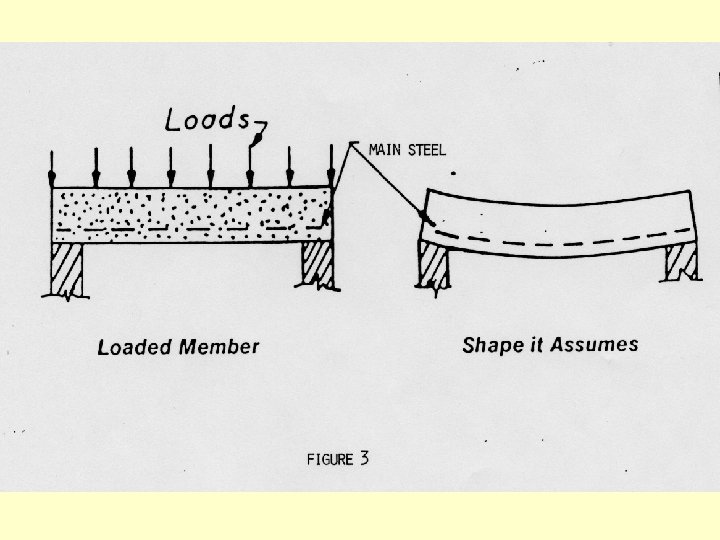
Main Tensile Reinforcement • Loaded beam supported at each end tends to sag
• Convex bottom of beam is in tension • Concave top is in compression • Without steel reinforcement near the bottom of the beam the concrete cannot withstand the tension Wooden Craft Sticks Demonstration!!
Temperature and Shrinkage Reinforcement ( T & S) • Temperature changes can cause – Expansion, or – Contraction • Shrinkage causes contraction • Expansion induces compressive forces in concrete & is not normally a problem • Contraction induces tension which must be counteracted
T & S Reinforcement (cont) • Steel bars used for contraction reinforcement are usually #3 or #4 bars spaced 12” to 18” apart with cross bars as needed for tying • Some concrete is reinforced (for T&S) with steel or plastic fibers added to the concrete during mixing
Reinforcement Location in Typical Sections • Location of structural steel reinforcement is crucial to the construction of any concrete structure • Steel placed near the center of a wall is usually T & S reinforcement unless it goes into a foundation, wall base, or floor
Reinforcement Location in Typical Sections • Tension is greater on the surface opposite of the forces (earth or stored material) • Steel reinforcement for tension needs to be placed as close to the tension surface as possible • There is a minimum cover to maintain to protect steel from corrosion & to insure adequate bond of concrete to steel
Materials • Bar Reinforcing Steel – Smooth - used for dowels – Deformed – the standard type of reinforcement • Protrusions or deformation conform to ASTM A 615 • Concrete bond with the steel is dependent on deformation
• Three grades of steel – Stuctural 40, 000 psi Grade 40 – Intermediate 60, 000 psi Grade 60 – Hard 75, 000 psi Grade 75 • Bar sizes from #2 (smooth) to #18 • Nominal diameter of bar = bar size/8 – #4 bar = 4/8 or ½ inch diameter
(From ASTM A 615)
How to Read Bar Markings
How to Read Bar Markings
How to Read Bar Markings
Example Rebar 1 extra rib = Grade 60 Producing Mill # 4 bar = ½” S = Billet (ASTM A 615)
Example Rebar Grade 60 Producing Mill # 5 bar =5/8” S = Billet (ASTM A 615)
Welded Wire Reinforcement (WWR) • Rolls – Difficult to flatten and position correctly – May be used for slabs on grade • Sheets – Delivered in flat sheets – Easier to position correctly – Heavier gauges available
WWR Example of poor positioning in slab
WWR continued • WWR generally comes in 6, 8 or 10 gage wire • Rectangular grid pattern - 6” by 6” is most common
Typical Bar Types
Placing • Surface condition of steel – no loose, flaky, scaly rust – Light covering of tight, yellow brown rust is beneficial in increasing the adhesion of concrete to steel – Remove oil from re-bars if excessive – Remove any mud from bars • Reinforcement - accurately positioned and secured as shown on the drawings
Placing - continued • Supports should hold bars firmly – Sufficient strength to carry the loads – Not displace too much concrete – Eliminate any opportunity for leakage or rusting – Close enough together that bars will not sag appreciably
Placing – Examples of supports
Placing – Examples of supports
Placing – Examples of supports
Placing – Examples of supports
Placing - continued • Splices – dependent upon – Bar diameter – Location in structural member – Location to other laps • Splice location typically not shown on the drawings • No lap length less than 12 inches – Typical lap = 30 D (D = bar diameter)
Cover • Construction Plans will show min cover • Cover = distance between concrete edge and reinforcing edge or between rebar edges • Typical cover distances – #4 bars in footings, ends exposed to earth = 3” – #4 bars, slab, exposed to earth or weather = 2”
Example Tolerances (Location) • Minimum cover shown on drawings: ± 3/8” • Location in wall or floor section: ± 3/8” of position shown on drawings • Lap or splice location: ± 1”, minimum splice length of 12” From NEH 645, Appendix E
Example Tolerances (Spacing) • Minimum spacing shown on drawings: ± 1/4” • Uniform spacing shown: ± 2” from theoretical location From NEH 645, Appendix E
Tolerances for Placement
Interpreting Steel Drawings Refer to composter drawings sheet 4
Interpreting Steel Drawings
Interpreting Steel Drawings
Review Questions (Use sheet 4 of the Composter drawings to answer) 1. 2. 3. 4. 5. What shape is a type 21 bar? What shape is a Mark W 2 bar? What is the spacing for the Mark W 4 bars? What is the tolerance for that spacing? What is the nominal diameter for the Mark W 4 bars?