Conceptual specifications Conceptual sketches Technical specifications DFHXKey basic

Conceptual specifications Conceptual sketches Technical specifications DFHX-Key basic concepts DFH concept DFH design - 1 unit Vs 2 units - Concept overview & pending inputs - DFHx installation problematics Specification drawings Manufacture Assembly & QA test Installation Operation Maintenance 1

DFHx: 1 unit Vs 2 units DFHx 2 DFHx 1 Power co DFHM Each IP 1 and IP 5 sides equipped with 2 cold powering chains of cryostats § Triplet insertion : DFHx – SC Link (DSH) – DFX § Matching sections : DFHm – SC Link - DFM el Service tunn nnel tu e Transvers DFX/DFM basic functions: § Electrical interface between SC Link and superconducting magnets § Supply cryogenics to the SCLink DS ≈5 0 m Hx DS Hm ≈8 m DFX ≈45 m nnel LHC tu nverters CP D 1 Q 2 b Q 3 Q 1 Q 2 a IP ≈80 m DFM D 2 DFHx : 1 unit Vs 2 units 2 x 13 k. A 8 x 0. 6 k. A HTS Superfluid @ 1. 9 K Liquid He @ 4. 5 K Gaseous He Heater Vacuum barrier HTS Mg. B 2 Nb. Ti Warm cable Splice 2 x 18 k. A 2 x 13 k. A DFHm DFHx 1 PT 3 x 7 k. A 12 x 2 k. A DFHx 2 PT PT Ghe <17 K Mg. B 2 UR: Service tunnel UL: Transverse tunnel SFHe @1. 9 K PT PT Mg. B 2 LHC tunnel PT Ghe @4. 5 K DSHx PT Splice DFX Ghe @4. 5 K Lhe @4. 5 K MBRD D 2 MBCRD Nb. Ti Beam SFHe @1. 9 K D 1 MBXF DFM DSHm

DFHx: 1 Unit Vs 2 Units § Specifications: § Proximity Current leads / Power supply § Mg. B 2 cable minimum bending radius : up to 1. 25 m § Current leads and HTS assembled and tested on surface § Advantages & Drawbacks at DFHx level 19 leads (<0. 2 k. A local powering) 1 cryostat per 18 k. A PC PC R>1. 5 m DFH : 1 unit DFH design - PC R>1. 5 m DFHx 1: High Current Integration UR (for information) Disconnector box – Current leads 18 k. A power supply requirements Volume tunnel Position interfaces (cryo/vacuum) 1 cryostat per 4 x 2 k. A R>1 m DFHx 2: Low current DFH : 2 units - Distance mini CL-DB up to 8 m Proximity PC-18 k. A leads > 4 m Very long DFHx (routing Mg. B 2 R=1. 5 m) e 1 packed zone (hydraulic + instru acquisition) - Distance CL-CDB < 1 m 18 k. A current leads – Power supply < 1 m Smaller boxes but 2 + interlink and spread over longer length 2 uncongested zones (hydraulic + instru acquisition) General dimensions Access to Mg. B 2 -HTS splices - Routing 19 leads Mg. B 2 radially long + wide Side access from flange - Split into 2 boxes spread radial opening of cable to 1. 5 m Rmin Allow sleeve sliding system 360 deg access to splices 3

DFHx sketch concept § DFH objectives : § § Connect the 19 electrical leads from the SCLink side to the current leads interfaces Monitor the electrical connection performance Ensure the cooling of electrical connections and cables Overview of the DFH: § § § 19 leads from 2 k. A to 18 k. A in a flow of gaseous helium below 20 K. T operation = 5 to 20 K Design pressure : PS≈4 bara Cryogenic lines 300 K Courtesy A. Ballarino Curren Leads Current Leads 20 K DFH envelope PT TT TT T< 20 K VT T< 20 K SCLink Layout of DFH electrical boxes 4

Overview DFHx life sequence and illustrative design Technical discussion open to comments, discussions 5

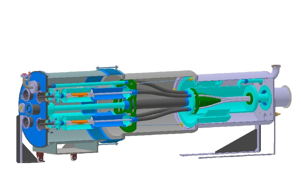
DFHx 1: Today status Safety relief devices +18 k. A Illustrative concept for discussion Port for pumping interfaces He. Vessel instrum. T-sensors V-taps VV instrum. TS instrum. +13 k. A Proposal In progress Need inputs DN 100 relief plate on vacuum volume -18 k. A -13 k. A ≈4 m Helium vessel fixed point Vacuum vessels config. Helium vessel <Ø 250 mm R=1. 5 m Possibility for spare Mg. B 2 -HTS splice Splices with Peek bilateral fixation to pipe Flexible routing Mg. B 2 cables. R=1. 5 m Splices individually routed: ≈Ø 1. 5 m Safety relief device covering DFHx + SCLink helium volumes Mass flow indiv. controlled PT Current leads flexible Mg. B 2 To DFHx 2 Current leads flexible Bellows He vessels DFHx 1 -SCLink Bellows VV vessels DFHx 1 -SCLink Note: thermal shield not shown G 10 guiding supports Sleeve principle for access CF flanges Connection to ground to design

Sequence proposal 3. Environment : no racks installed The Mg. B 2 cables are internally routed and fixed in radial position in the DFHx 1 to match the current leads interfaces. (+ installation instrumentation) 1. SCLink cables ends on supports Matching lead with Current lead radial positions (opening of cables bundle) SCLink is pre-assembled before all other components. Fixed in position on DFX side. Interface with DFHx 1 located within cm. The cable bundle is reduced to minimum diameter for transport purposes. UR Interface flange with DFHx 1 MGB 2 cable protected DFHx 2 UL 4. SCLink final cryostat DFHx 1 Mg. B 2 cables with extra length 2. Insertion module 1: VV 1+He. V 1 The DFHx 1 module is “rolled” around the SCLink cable all the way from DFHx 2. Few cm positioning flexibility Insertion module 2 (sleeves opened) Once cables are radially positioned, the internal helium vessel is closed with Mg. B 2 extra length going out in individual tubes (to ease access to individual splice, ease welding, perform clean splice, increase & individualise turbulent flow locally at splice level). 5. Installation interfaces with current leads Installation of interface with DFHx 2 and interface flange with current leads.

Sequence proposal 6. Assembly current leads Racks and current leads are installed around the DFHx 1. flexible ends of current leads are connected to DFHx 1 interface flange. 9. Close sleeves It is suggested to use standard interconnection sleeves with standard tooling for cutting and welding. 10. Close vacuum vessel The vacuum vessel is a sleeve itself closed with standard elastomer Orings (LHC type connection). ← to DFHx 2 7. Adjust Mg. B 2 leads to length HTS end lengths of current leads are fixed, in order to face few cm positioning of the SCLink in the tunnel + solder on “fresh unsoldered Mg. B 2 + to optimise the splice performance, it is suggested to cut the extra length of Mg. B 2 at this stage. 8. Splices are independent (for DFHx 1 18 k. A and 13 k. A leads). Other splices can be independently protected when working around. Installation of V-taps 11. Transient phase The insulation vacuum is common with current leads and SCLink. Pumps and relief plates are assembled on module 1. During cool down, the internal helium vessel is fixed in the middle, splices are longitudinally fixed relatively to the helium vessels. Thermal contraction of the cable is covered form the entry in the DFHx 1. The helium vessels contractions is covered on SCLink side by bellows, on current leads side by current leads internal bellows. The geometry allow to individually control each mass flow around splices.

Next meetings 10

§ Handling Mg. B 2 cable at installation : 2 proposals Transport configurations Assumptions: § § § DFHx=DFHx 1 & DFHx 2 SCLink rolled on a max Ø 4 mx 2. 5 m turret DFH assembled after SCLink, before CL & PC Option#1: Sclink transported with compact Mg. B 2 cable configuration: opened at installation DFHx 2 DFHx 1 Mg. B 2 cable packed + removable protection Option#2: Sclink tested and transported with partially pre-routed cables: partially opened at installation. After installation DFHx 2 DFHx 1 Mg. B 2 cable in final configuration Option#1 Option #2 SCLink transport to UR • SCLink rolled on turret after SM 18 test (removable protection) • Simple unrolling from DFX end • Reduced SCLink vacuum jacket flange diameter • Difficulties to roll 4 m protective boxes (10 m apart) on the turret • Feasibility of unrolling the turret to be proven • Bigger SCLink vacuum jacket flange Testing phase • Mg. B 2 cable is packed after testing in SM 18 and re-opened in the tunnel • Mg. B 2 cable is never touched between testing and tunnel installation. • • • • • Installation & integration Protection of Mg. B 2 cable Match angularly SCL and HTS leads Routing of Mg. B 2 leads Vacuum vessel dimensions Pressure welding & QA Interlink dimensions HTS lengths Thermal contraction Interlink Instrumentation routing Mg. B 2 protection must be removed at some point Routing within He vessel Manual forming of Mg. B 2 leads Minimised to compact diameter of cable bundle Big PED weld to realise Minimised to compact cable bundle diameter Minimised Not solved yet Done in the tunnel Never touched after testing in SM 18 Need extra length of flexible (1 m) DFH length Only flexible part Scaled to He vessel diameter (to slide vessels). Big No big welds (max DN 100) Inner Ø > then He vessel OD (DN 350) Bigger interlink HTS + 1 m May use big interlink DN 350… TBD Done at the surface before testing 11
- Slides: 11