Concepts of RCCPCC For Integrated group Basics Loads

Concepts of RCC/PCC For Integrated group

Basics - Loads Bending T Compression Shear Tension Buckling Torsion

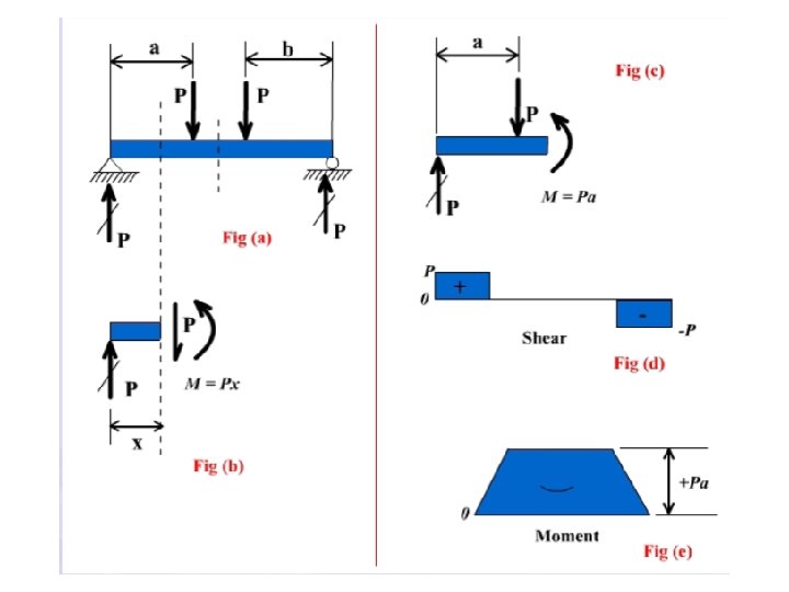
Basics – Forces on Beams • Vertical Loads • Shear Force • Bending Moment

TYPES OF SUPPORTS Simple V H Hinged V H M V Fixed

Introduction to Beams are supported in structures via different configurations

Introduction to Beams • A beam is a horizontal structural member used to support loads • Beams are used to support the roof and floors in buildings 7

Beam Theory • Consider a simply supported beam of length, L. The cross section is rectangular, with width, b, and depth, h. h b L 8

Beam Theory • An area has a centroid, which is similar to a center of gravity of a solid body. • The centroid of a symmetric cross section can be easily found by inspection. X and Y axes intersect at the centroid of a symmetric cross section, as shown on the rectangular cross section. Y - Axis h/2 X - Axis h/2 b/2 9

Beam Theory • An important variable in beam design is the moment of inertia of the cross section, denoted by I. • Inertia is a measure of a body’s ability to resist rotation. • Moment of inertia is a measure of the stiffness of the beam with respect to the cross section and the ability of the beam to resist bending. • As I increases, bending and deflection will decrease. • Units are (LENGTH)4, e. g. in 4, ft 4, cm 4 10

Beam Theory • I can be derived for any common area using calculus. However, moment of inertia equations for common cross sections (e. g. , rectangular, circular, triangular) are readily available in math and engineering textbooks. • For a rectangular cross section, X-axis (passing through centroid) h b • b is the dimension parallel to the bending axis. h is the dimension perpendicular to the bending axis. 11
 –")
Beam Formula • Shear and moment diagrams • Simple beam (uniformly distributed load) – Reaction force formula – Maximum moment formula • Simple beam (concentrated load at center) – Reaction force formula – Maximum moment formula

Beam Formulas • Similar loading conditions = similar shear and moment diagrams • Standard formula can represent the magnitude of shear and moment based on loading condition • Magnitude of shear and bending moment depend on – Span length of beam – Magnitude of applied load – Location of applied load
 Uniform load = 1000 lb/ft")
Shear and Moment Diagrams Simple Beams (Uniformly Distributed Load) Uniform load = 1000 lb/ft L = 20 ft Uniform load = 1200 lb/ft L = 35 ft

Reaction Force Formula A w L Beam Diagram B

Reaction Force Formula B A RA + L RB

Reaction Force Formula w A RA + Since L B RB

Maximum Moment Formula w A L Shear Moment B
 w A B L Beam Diagram (at")
Beam Formula Simple Beam (Uniformly Distributed Load) w A B L Beam Diagram (at center)
 Find a formula for the end reaction forces")
Simple Beam (Concentrate Load at Center) Find a formula for the end reaction forces and for the maximum moment for a simply supported beam with a single concentrated load, P, applied at center span. P L
")
Your Turn Simple Beam (Concentrate Load at Center)
")
Your Turn Simple Beam (Concentrate Load at Center)
 P (at point of load) L")
Beam Formula Simple Beam (Concentrated Load at Center) P (at point of load) L (at point of load)

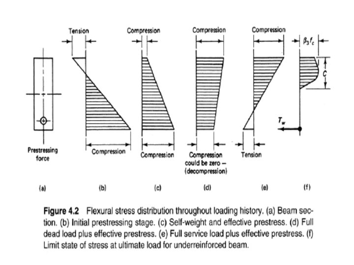
CONCRETE BEAM Loading stages fc f’c 1 2 ft f’t ft = f’t fc f’c 3 fs fy fc f’c fc = f’c 4 fs = fy 5 fs = fy 1 : Little weight 2 : Concrete stress reaches modulus of rupture 3 : Concrete cracks and steel resists tension 4 : Steel yields 5 : Collapse condition

Structural steel All dim. in mm

fy fy /1. 15 = 0. 87 fy 1. 00 fy 0. 87 fy design value stress N / sq mm 400 415 DESIGN STRENGTH OF STEEL 0 . 002. 004. 005 strain HIGH YIELD STRENGTH BARS design value strain MILD STEEL

CHARACTERISTIC STRENGTH OF STEEL Stress - N / sq mm 500 450 Fe 415 400 350 300 Fe 250 200 150 100 50 0 0. 1 0. 2 0. 3 0. 4 0. 5 0. 6 es (%)

DESIGN STRENGTH OF CONCRETE 1. 00 fck stress 0. 67 fck design value 0. 446 fck ecu = 0. 0035 0. 001 0. 002 strain 0. 003

CHARACTERISTIC STRENGTH CONCRETE 1. 00 fck stress 0. 67 fck ecu 0. 001 0. 002 strain 0. 0035

Singly reinforced beam Working Stress σcb Ast nd/3 C NA jd h d nd εc εs σst T

CONCRETE STRESS BLOCKS ecu 0. 446 fck k xu = 0. 0035 3 xu / 7 xu C 4 xu / 7 Neutral axis O ACTUAL STRESS BLOCK O STRAIN DIAGRAM O DESIGN STRESS BLOCK

Singly reinforced beam Limit State b NEUTRAL AXIS C d - kxu d xu kxu ecu T As esu


PURE BENDING RECTANGULAR SECTION k xu C 4 xu / 7 C d - kxu 3 xu / 7 k. xu 0. 446 fck T Total compression A B C = b 0. 446 fck (3 xu ) + 0. 446 fck 2 ( 4 x u ) 7 3 7 = 0. 36 fck. x u. b

Distance of center of gravity of compression force from top fiber, k. x u = b A. 3 x u. 1 + B ( 3 x u + 3 . 4 x u ) C 7 2 7 8 7 = 0. 416 x u ie k = 0. 416 Total compression = Total tension 0. 36 fck. x u b = 0. 87. f y. As from which, ku = x u / d = 2. 417 fy (p) where p = As / bd fck Ultimate Moment Mu = C (d - k x u) = 0. 36 fck. x u. b( d – 0. 416 x u) = Q. bd 2

where Q = 0. 36 k u fck ( 1 – 0. 416 k u) Solving earlier equation for x u gives , __________ k u = x u / d = 1. 2 1 - 4. 62 Mu / fck bd 2

FAILURE IN FLEXURE FAILURE IN BOND

SHEAR STRESS

SHEAR FORCE EQUILIBRIUM SHEAR FORCE Comp. force in concrete RC BEAM Aggregate interlock force Reinforcement Dowel force in steel

The shear force V is resisted by Vc , from the un-cracked concrete compression zone, Vd, from the dowel action of longitudinal reinforcement. Va, from vertical component of the force due to aggregate interlock or interface shear transfer. V = Vc + Vd + Va

SHEAR CONCEPTS Compression diagonal Compression chord Tension chord d’ = cover + / 2 Tension diagonal s d d d – d’ Shear resisted by stirrups Vu = stress (area of stirrup)(number of stirrups in length ‘d’) = 0. 87 fy x Av x d / s

SHEAR CONCEPTS 10 mm dia stirrups 1 No 20 mm dia bent bar 5 Nos 22 mm dia bars Shear resisted bent up bars 0. 87 fy As Sin 45

Location of Maximum Shear for Beam Design d Compression fan carries load directly to support

CLASSIFICATION OF LIMIT STATES 1 COLLAPSE Compression Tension Shear Bending Torsion 3 SERVICEABILITY Deflection Cracking Vibration 2 STABILITY Sliding Overturning Buckling Sinking 4 DURABILITY Fire damage Environmental attack

SHEAR FAILURE

STRONGER BEAMS d xu dc 0. 0035 esc DOUBLY REINFORCED

Df xu C T Df xu Case 1 xu< Df 3 xu/7 T Df FLANGED BEAMS Case 2 a 3 xu/ 7 < Df 3 xu/7 xu T Case 2 b 3 xu/ 7> Df

Various Possible Geometries of Flanged Beams T Double T Box L I

FLANGE WIDTH FOR T BEAMS bf bf x 1 bw x 1 x 2 bw x 2 (a) For T beams bf = lo/6 +bw + 6 Df and bf = bw + x 1 + x 2 ; whichever is less (b) For isolated T beams bf = 0. 5 lo / (lo/b +4) + bw and bf = b; whichever is less bf = effective width of flange bw = breadth of web b = actual width of flange lo = distance between points of zero moment in a beam ; (for continuous beams lo = 0. 7 Le) Df = thickness of slab / flange x 1 , x 2 are half of clear distance between adjacent beams

BAR ANCHORAGE T Ld T = 0. 87 fy. As = 0. 87 fy 2 4 R = fb. Ld. R = T fb. Ld. = 0. 87 fy 2 4 Ld = 0. 87 fy / 4 fb

BAR ANCHOR LENGTH fy N / mm 2 Anchor length for conc. grade of : M 20 M 25 M 30 250 45. 3 38. 8 36. 3 415 47. 0 40. 3 37. 6 500 56. 6 48. 6 45. 3 fy N/mm 2 Anchor length for conc. grade of : M 20 M 25 M 30 250 45 40 415 50 40 500 57 50 45

LAPPING Outer face of concrete OF Lap length Cover REBARS Slope 1 in 6

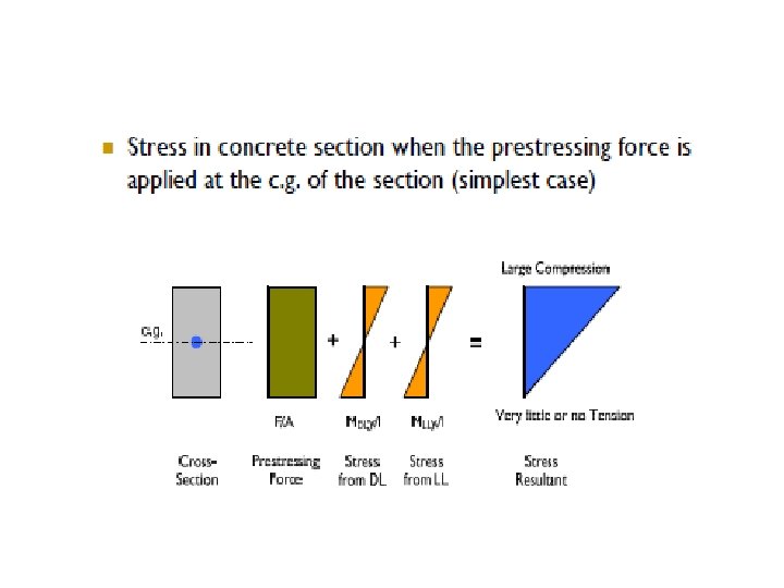
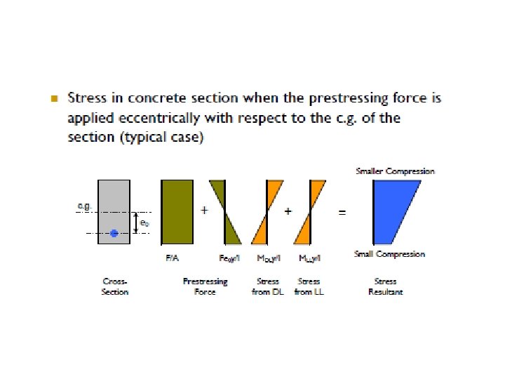
PRESTRESSED CONCRETE • WHAT IS WEAKNESS OF RCC? – IN CONCRETE, COMPRESSIVE STRENGTH IS HIGH – IN TENSION ZONE CONCRETE CRACKS AND IS INEFFECTIVE • CAN WE DO SOMETHING? – DON’T ALLOW TENSION

PRESTRESSING IS OLD CONCEPT

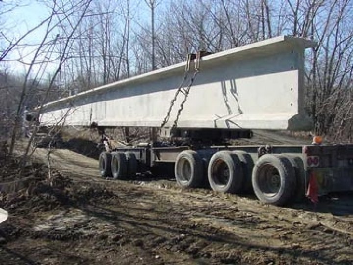
CONCRETE SLEEPER, MOST COMMON PSC ELEMENT

DESIGN OF CONCRETE BEAMS Working Stress Method
- Slides: 63