COMPUTER NETWORKS Medium Access Sub layer q q

COMPUTER NETWORKS

Medium Access Sub layer q q The channel allocation problem Multiple access protocols q q q ALOHA Carrier sense multiple access protocols Collision free protocols Wireless LANs Data link layer switching

Medium Access Sublayer The protocols used to determine who goes next on a multi-access channel belong to a sublayer of the data link layer called the MAC (Medium Access Control) sublayer. The MAC sublayer is especially important in LANs, particularly wireless ones because wireless is naturally a broadcast channel. WANs, in contrast, use point-to-point links, except for satellite networks

The Channel Allocation Problem: � How to allocate a single broadcast channel among competing users. Solution: Static allocation schemes Dynamic allocation schemes

Static Channel Allocation In static channel allocation scheme, a fixed portion of the frequency channel is allotted to each user. For N competing users, the bandwidth is divided into N channels using frequency division multiplexing (FDM), and each portion is assigned to one user. However, it is not suitable in case of a large number of users with variable bandwidth requirements. Better use Dynamic Allocation Scheme.

Dynamic Allocation Scheme Here frequency bands are not permanently assigned to the users. The mechanism is similar to Statistical TDM, but with consideration to minimizing interference among users. Instead channels are allotted to users dynamically as needed, from a central pool. This allocation scheme optimizes bandwidth usage and results is faster transmissions. Dynamic channel allocation is further divided into centralized and distributed allocation

Dynamic Allocation Schemes: Assumptions Independent Traffic. The model consists of N independent stations, i. e. Non Cooperating stations. Single Channel. A single channel is available for all communication which is shared by all. Observable Collisions. If two stations transmit frames simultaneously, it results in a collision which can be detected by stations. Continuous or Slotted Time. Frame transmission can begin at any instant in case of Continuous time. Alternatively, time may be slotted or divided into discrete intervals in case of Slotted time. Carrier Sense or No Carrier Sense. With the carrier sense assumption, stations can tell if the channel is in use before trying to use it.

Multiple Access Protocols ALOHA � Aloha, being the first multiple access protocol, proposes how multiple terminals can access the medium without interference or collision. � There are two different versions of ALOHA: 1. Pure Aloha 2. Slotted Aloha

Pure Aloha Here, a station transmits whenever it has data to transmit. It does not check whether the channel is busy or not before transmitting. Whenever a frame is transmitted, the station expects an acknowledgment from the receiver. If the acknowledgment is not received within the timeout period, then a station picks random back-off time (to avoid collision) before retransmission of frame. This scheme works very well in case of small networks where the load is not much but not for largely loaded networks. This has led to the development of Slotted Aloha.

In pure ALOHA, users transmit frames whenever they have data; users retry after a random time for collisions � Efficient User ` and low-delay under low load A B C D E Collision Time Collision

ALOHA Collisions happen when other users transmit during a vulnerable period that is twice the frame time � Synchronizing senders to slots can reduce collisions CN 5 E by Tanenbaum & Wetherall, © Pearson Education-Prentice Hall and D. Wetherall, 2011

Pure Aloha Flowchart of pure aloha

Slotted Aloha In slotted ALOHA, the time of the shared channel is divided into discrete intervals called Slots. The stations are eligible to send a frame only at the beginning of the slot and only one frame can be sent per slot. If a slot is missed, the station has to wait until the next slot to transmit a frame. When two stations try to send at the beginning of a slot, there might be a chance of collision. Here collisions still take place but gets reduced largely.

Slotted Aloha Frames in slotted aloha network

Numerical Problems on ALOHA System

Carrier Sense Multiple Access Protocols In LANs, however, it is possible for stations to detect frames from other stations. This feature can be used to improve the performance of the MAC protocols. Protocols in which stations listen for a carrier (i. e. , a transmission) and act accordingly are called carrier sense protocols. But Collisions still occur due to propagation delay.

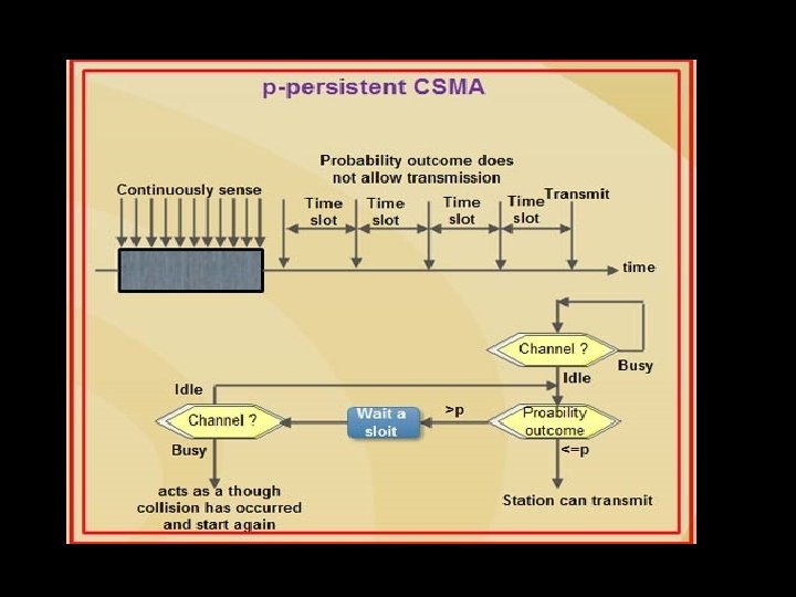
Carrier Sense Multiple Access Protocols CSMA access modes� 1 -persistent: The node senses the channel, if idle it sends the data Otherwise it keeps on checking the medium (continuously) and transmit (with 1 probability) when the channel gets idle. � Non-Persistent: The node senses the channel, if idle it sends the data Otherwise it checks the medium after a random amount of time (not continuously) and transmit (with 1 probability) as soon as the channel gets idle. This leads to better channel utilization but longer delays than 1 -persistent. � P-persistent: Here slotted channels are used. The node senses the medium, if idle it sends the data with p probability. If the data is not transmitted ((1 -p) probability) then it waits for some time and checks the medium again, now if it is found idle then it sends with p probability.

Carrier Sense Multiple Access Protocols Persistent and non-persistent CSMA protocols are definitely an improvement over ALOHA. Another improvement is for the stations to quickly detect the collision and abruptly stop transmitting, (rather than finishing them). This strategy saves time and bandwidth. This mechanism is known as CSMA/CD (CSMA with Collision Detection)

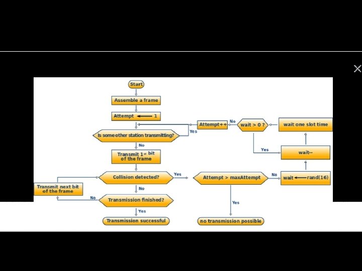
CSMA – Collision Detection

Collision Free Protocols These protocols resolve the contention for the channel (i. e. No collisions at all). Examples �A Bit-Map Protocol: Pass a bit “ 1” to reserve a time slot. � Token Passing: A stations needs to get a token, before sending a frame and then pass the token to other stations. � Binary Countdown: Stations use their addresses instead of bit “ 1” or token. Hence less bandwidth wastage to occupy channel.

Collision-Free – Bitmap Collision-free protocols avoid collisions entirely � Senders must know when it is their turn to send The basic bit-map protocol: � Sender set a bit in contention slot if they have data � Senders send in turn; everyone knows who has data

Collision-Free – Token Ring Token sent round ring defines the sending order � Station with token may send a frame before passing � Idea can be used without ring too, e. g. , token Token bus Station Direction of transmission

Collision-Free – Countdown Binary countdown improves on the bitmap protocol �Stations send their address in contention slot (log N bits instead of N bits) �Medium ORs bits; stations give up when they send a “ 0” but see a “ 1” �Station that sees its full address is next to send
 How long does a station, s, have to wait in the worst")
Q 1) How long does a station, s, have to wait in the worst case before it can start transmitting its frame over a LAN that uses the basic bit-map protocol? Q 2) In the binary countdown protocol, explain how a lower-numbered station may be starved from sending a packet.

Wireless LAN Protocols • • • Nowadays, more and more networks are operating without cables, within the wireless mode. Wireless LANs use high-frequency radio signals, infrared beams, or lasers to speak between the workstations, file servers, or hubs. Wireless LAN is formed by connecting different devices through wireless communication to form an area network. WLAN follows a typical standard named IEEE 802. 11.

Wireless LAN - WLAN • WLAN stands for Wireless Local Area Network. WLAN is a local area network that uses radio communication to provide mobility to the network users, while maintaining the connectivity to the wired network. A WLAN basically, extends wired local area network. • WLAN’s are built attaching a device called the access point(AP) to the edge of the wired network. Clients communicate with the AP using a wireless network adapter which is similar in function to a Ethernet adapter. It is also called a LAWN that is Local area wireless network. • The performance of WLAN is high compared to other wireless networks. The coverage of WLAN is within a campus or building or that tech parks. The standards of WLAN are Hiper. LAN, Wi-Fi and IEEE 802. 11. It offers service to the desktop laptop, mobile application and all the devices that works on the Internet. WLAN is an affordable method and can be set up easily. • WLAN gives users the mobility to move around within a local

Wireless LAN - WLAN Characteristics : • Seamless operation. • Low power for battery use. • Simple management, easy to use for everyone. • Protection of investment in wired networks. • Robust transmission technology Advantages : • Installation speed and simplicity. • Installation flexibility. • Reduced cost of ownership. • Reliability. • Mobility. • Robustness. Disadvantages : • Slower bandwidth. • Security for wireless LAN’s is the prime concern. • Wireless networks cost four times more than the wired network cards.

Sr. No. 1 2 Key LAN stands for Local Area Network. WLAN stands for Wireless Local Area Network. Connection Type LAN connections includes wired as well as wireless connection technologies. WLAN connections are completely wireless technology based. Coverage LAN covers a large area like WLAN slso covers a large building. regions like building, office etc. Cost LAN connections are less expensive, more secure that wireless connections of WLAN connections are more expensive and considered less secure than wired connections. Complexity Installation of LAN is relatively cheaper but complex to install. It requires Routers, switches to connect wires. Installation of WLAN is costly but simple. Routers, switches are not needed to connect wires. 4 5 7 WLAN Stands for 3 6 LAN Performance LAN provides good performance and impact of weather is limited. WLAN provides high performance but may get impacted in bad weather. Mobility WLAN is highly mobile in nature. No ethernet is required to connect devices to WLAN. LAN has limited mobility. LAN needs ethernet to connect devices.
 is unusable in wireless networks because")
Wireless LAN Protocols CSMA/CD (CSMA with Collision Detection) is unusable in wireless networks because The sender is only able to transmit and receive packets on the medium but is not able to sense data traversing that medium. � Most common problems are Hidden Node and Exposes Node Problems (Also called Hidden Terminal or Hidden Station Problem) � A and C are hidden terminals when transmitting to B B and C are exposed terminals when transmitting to A and D

Wireless LANs – Hidden terminals are senders that cannot sense each other but nonetheless collide at intended receiver �A and C are hidden terminals when sending to B
, the")
Wireless LANs – Hidden terminals In wireless LANs ( wireless local area networks), the hidden terminal problem is a transmission problem that arises when two or more stations who are out of range of each other transmit simultaneously to a common recipient. This is prevalent in decentralised systems where there aren’t any entity for controlling transmissions. This occurs when a station is visible from a wireless access point (AP), but is hidden from other stations that communicate with the AP. Problem Illustration Suppose that there are three stations labelled STA, STB, and STC, where STA and STC are transmitting while STB is receiving. The stations are in a configuration such that the two transmitters STA and STC are not in the radio range of each other. This is shown in the following figure −

Wireless LANs – Exposed terminals are senders who can sense each other but still transmit safely (to different receivers) �B A and C D are exposed terminals
, the exposed")
Wireless LANs – Exposed terminals In wireless LANs (wireless local area networks), the exposed terminal problem is a transmission problem that arises when a transmitting station is prevented from sending frames due to interference with another transmitting station. This is prevalent in decentralised systems where there aren’t any entity for controlling transmissions. This occurs when a station is visible from a wireless access point (AP), but not from other stations that communicate with the AP. Problem Illustration Suppose that there are four stations labelled STA, STB, STC, and STD, where STB and STC are transmitters while STA and STD are receivers at some slot of time. The stations are in a configuration such that the two receivers STA and STD are out of radio range of each other, but the two transmitters STB and STC are in radio range of each other. This is shown in the following figure −

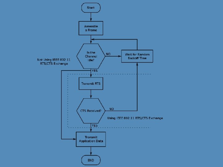
Solution to Hidden and Exposed Terminals Solution The hidden/exposed terminal problem is solved by the MAC (medium access control) layer protocol IEEE 802. 11 RTS/CTS, with the condition that the stations are synchronized and frame sizes and data speed are the same. RTS stands for Request to Send and CTS stands for Clear to Send. A transmitting station sends a RTS frame to the receiving station. The receiving station replies by sending a CTS frame. On receipt of CTS frame, the transmitting station begins transmission. Any station hearing the RTS & is close to the transmitting station should remain silent long enough for the CTS. Any station hearing the CTS & is close to the receiving station should remains silent during the data transmission. In the above example, station STC does not hear RTS from station STA, but hears CTS frame from station STB. So, it understands that STB is busy defers its transmission thus avoiding

Wireless LAN Protocols Solution to Hidden Node and Exposed Node Problem � MACA (Multiple Access with Collision Avoidance Sender uses RTS (Request To Send) frame to inform All stations before transmitting data frame. Receiver uses CTS (Clear To Send) frame to inform All stations before replying to senders. The MACA protocol. (a) A sending an RTS to B. (b) B responding with a CTS to A.
 Consider five wireless stations, A, B, C, D, and E. Station A")
Q 3) Consider five wireless stations, A, B, C, D, and E. Station A can communicate with all other stations. B can communicate with A, C and E. C can communicate with A, B and D. D can communicate with A, C and E. E can communicate A, D and B. (a) When A is sending to B, what other communications are possible? (b) When B is sending to A, what other communications are possible? (c) When B is sending to C, what other communications are possible? Q 4) Six stations, A through F, communicate using the MACA protocol. Is it possible for two transmissions to take place simultaneously? Explain your answer

Data Link Layer Switching One shared LAN can limit us in terms of: � Distance Answer: � Number (why? ) It’s a fault with the cable tech. of nodes (why? ) Answer: The maximum number of nodes on a LAN depends on the media type, network protocol, and (at least for the IPv 4 protocol) the network address class. How do we scale to a larger, more efficient networks? � We must be able to interconnect LANs.

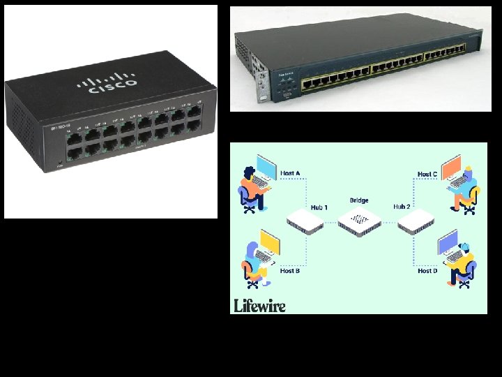
Terminology Bridge � Old fashioned name for a LAN switch, e. g. , Ethernet switch � Works at the link (Ethernet) layer Switch � Generic device Router � Switch term for a low-level interconnection that works at the network (IP) layer Gateway � Generic device term for a high-level interconnection

Bridges Connected to different LANs over ports Operate in “promiscuous mode” � receives packet on one port and forwards it to the outgoing port Example. � It From A to D is “never” a communication endpoint itself What should each bridge do with an incoming frame? � normally forwards all multicast and broadcast frames to all the receivers.
 Bridge connecting two multidrop LANs. (b) Bridges (and a hub) connecting seven point-to-point")
(a) Bridge connecting two multidrop LANs. (b) Bridges (and a hub) connecting seven point-to-point stations.

Learning Bridges extend the Link layer: � Use but don’t remove Ethernet header/addresses � Don’t inspect higher layer headers � May need to store the packet Bridges use Backward learning algorithm � At first, bridge doesn’t know where any address is. � So it sends incoming frame “everywhere” � But, the incoming frame carries a source address. So it stores it in database (memory). � If an incoming frame has a destination address it knows (from database), it sends that frame only there

Backward Learning Algorithm Backward learning algorithm � At first, bridge doesn’t know where any address is. � So it sends incoming frame “everywhere” � But, the incoming frame carries a source address. So it stores it in database (memory). � If an incoming frame has a destination address it knows (from database), it sends that frame only there

Protocol processing at a bridge.

Bridges with two parallel links.
 Goals: � To avoid loops by finding redundant links in")
Spanning Tree Protocol (STP) Goals: � To avoid loops by finding redundant links in a network and shutting them down. � To prevent bridging loops, redundant paths must be identified and blocked. � Not only does spanning-tree blocks redundant paths but also reopens them in case of a link failure. Working: � STP computes a tree that spans all switches in a network. � All switches communicate using Bridge Protocol Data Units (BPDU) with each other. � A reference point is agreed by all switches in a network and based on this reference point all redundant links are identified and blocked and only one path is allowed to forward traffic. � If a link that was previously forwarding fails STP automatically enables one of redundant blocked links as the new active path.

spanning tree connecting five bridges. The dashed lines are links that are not part of the spanning tree.
 Which device is in which layer. (b) Frames, packets, and headers.")
Network Devices (a) Which device is in which layer. (b) Frames, packets, and headers.

Bridges vs. Routers Bridge Router
")
VIRTUAL LOCAL AREA NETWORKS (VLAN)

A building with centralized wiring using hubs and a switch.
 split one physical LAN into multiple logical LANs, for")
Virtual LANs VLANs (Virtual LANs) split one physical LAN into multiple logical LANs, for management reasons � Ports are colored according to their VLAN � 802. 1 Q frames carry a color tag (VLAN identifier) Length/Type value is 0 x 8100 for VLAN protocol Ethernet Frame and Virtual LAN protocol

Two VLANs, gray and white, on a bridged LAN.
![VLANs [ Virtual Local Area Networks]](http://slidetodoc.com/presentation_image_h2/224bc32bc9d7b04c8b36ce92360726e2/image-57.jpg "VLANs [ Virtual Local Area Networks]")
VLANs [ Virtual Local Area Networks]
- Slides: 57