Computer Networks An Open Source Approach Chapter 3


![IEEE 802 MAC Address Unicast address is for single host [i. Mac] MAC address:](https://slidetodoc.com/presentation_image_h/dda47a7ce39abe269cf69fd9b4c70ed9/image-29.jpg "IEEE 802 MAC Address Unicast address is for single host [i. Mac] MAC address:")


 Operations Transmitter: generate a bit sequence by modulo 2")


![In the following example [Step 1] [frame content (F): 11010001110 (11 bits) [mbit]]](https://slidetodoc.com/presentation_image_h/dda47a7ce39abe269cf69fd9b4c70ed9/image-40.jpg "In the following example [Step 1] [frame content (F): 11010001110 (11 bits) [mbit]]")
![Cyclic Redundancy Check frame content (F): 11010001110 (11 bits) [m-bit] pattern (B): 101011 (6](https://slidetodoc.com/presentation_image_h/dda47a7ce39abe269cf69fd9b4c70ed9/image-41.jpg "Cyclic Redundancy Check frame content (F): 11010001110 (11 bits) [m-bit] pattern (B): 101011 (6")


 is needed when multiple")


 Carrier sense The node senses if")


 A 58")

")


 3. 2.")
 A widely used protocol in traditional dial-up lines or ADSL")

 Derived from an early protocol, Synchronous")


 Asynchronous Response Mode (ARM) The secondary station can")


")
 Carries control information only Both positive and negative acknowledgments are")
 Also used for the control purpose, but it does not")

 PPP is a standard protocol defined by IETF")


![Major transitions in the diagram [Up] Dead ➝ Establish [Open] Establish ➝ Authenticate](https://slidetodoc.com/presentation_image_h/dda47a7ce39abe269cf69fd9b4c70ed9/image-86.jpg "Major transitions in the diagram [Up] Dead ➝ Establish [Open] Establish ➝ Authenticate")
![[Up] Dead ➝ Establish The transition is invoked by carrier detection or network](https://slidetodoc.com/presentation_image_h/dda47a7ce39abe269cf69fd9b4c70ed9/image-87.jpg "[Up] Dead ➝ Establish The transition is invoked by carrier detection or network")
![[Open] Establish ➝ Authenticate The LCP starts to set up the connection by](https://slidetodoc.com/presentation_image_h/dda47a7ce39abe269cf69fd9b4c70ed9/image-88.jpg "[Open] Establish ➝ Authenticate The LCP starts to set up the connection by")
![[Success] Authenticate ➝ Network Authentication is optional in PPP, but if it is](https://slidetodoc.com/presentation_image_h/dda47a7ce39abe269cf69fd9b4c70ed9/image-89.jpg "[Success] Authenticate ➝ Network Authentication is optional in PPP, but if it is")
![[Close] Network ➝ Terminate The termination happens in many situations, including loss of](https://slidetodoc.com/presentation_image_h/dda47a7ce39abe269cf69fd9b4c70ed9/image-90.jpg "[Close] Network ➝ Terminate The termination happens in many situations, including loss of")


![IPCP provides the configuration option [within Header / Data field] IP-Addresses: is obsolete](https://slidetodoc.com/presentation_image_h/dda47a7ce39abe269cf69fd9b4c70ed9/image-101.jpg "IPCP provides the configuration option [within Header / Data field] IP-Addresses: is obsolete")

 The Need for PPPo. E As")


 Ethernet evolution: A big picture The Ethernet MAC")


 The DIX (DEC-Intel-Xerox) standard specified this field to be a code")


 The MAC client (IP, LLC, etc. ) asks for frame transmission (2)")
 Wait for a period of time called inter-frame gap (IFG) The time")

 Start to transmit the frame (6) In the half-duplex mode, the transmitter")
 In case no collision is detected during transmission, the frame is transmitted")

 Abort the current transmission and attempt to schedule another transmission (10) The")
 On an attempt to retransmit, a back-off time interval in units of")

 The arrival of a frame is detected by the physical layer of the")
 If the frame is too long, it is dropped and the error")


 If the switch finds it has a lower identifier than that of the")

 can provide for the logical configuration of LANs")


- Slides: 176
Computer Networks An Open Source Approach Chapter 3: Link Layer 1
Content 3. 1 General issues 3. 2 Point-to-point protocol 3. 3 Ethernet (IEEE 802. 3) 3. 4 Wireless links 3. 5 Bridging 3. 6 Device drivers of a network interface 3. 7 Summary Chapter 3: Link Layer 2
Communication at the Data-Link Layer 3
Nodes and Links 4
3. 1 General Issues 3. 1. 1 Framing 3. 1. 2 Addressing 3. 1. 3 Error Control and Reliability 3. 1. 4 Flow Control 3. 1. 5 Medium Access Control 3. 1. 6 Bridging 3. 1. 7 Link-Layer Packet Flows 5
Several issues for successful data transmission For example, crosstalk noise between adjacent link pairs can unexpectedly impair transmission signals and result in errors, so the link layer needs proper error control mechanisms for reliable data transmission The transmitter might transmit at a rate faster than what the receiver can handle, and has to slow down If multiple nodes share a LAN, an arbitration mechanism is required to determine who can transmit next For interconnected LANs, we need to bridge different LANs to extend packet forwarding beyond a single LAN 6
Link layer Manages physical links for the upper-layer functions Exempts the upper layers from the tedious work of controlling the physical link Alleviates upper-layer protocol design and makes it virtually independent of physical transmission characteristics General issues in designing link layer Framing, addressing, error control, flow control, access control, and interfaces with other layers 7
8
Given a vast variety of real-world link technologies summarized in the following table, we focus on only a few mainstream link technologies 9
10
Framing Data transmitted on a physical link are packed in units of frames A frame contains two main parts Control information in the header Data in the payload Control information Destination address, the upper-layer protocol in use, the error detection code, etc. , are critical to frame processing Data The data part handed from the upper layer is encapsulated with the control information into the frame 11
Because frames are transmitted as raw bit streams in the physical layer, the link layer service should Turn frames into bit streams upon transmission Break the bit stream into frames upon reception Most literature uses the two terms, packets and frames, interchangeably, but we specifically refer to a packet data unit in the link layer as a frame 12
Addressing A link-layer address, often presented in a numeric form of a certain length, specifies the identity of a host When host A wants to transmit a frame to host B, it includes its address and host B ’s address as the source and destination addresses in the frame’s control information 13
Error Control and Reliability Frames transmitted over physical media are subject to errors, and the receiver must be capable of detecting these errors through a certain mechanism Upon detecting an error, the receiver may simply drop the frame, or it may acknowledge the error occurrence and request that the transmitter retransmit the frame For data-link technology like Ethernet The bit error rate is extremely low, so the retransmission mechanism could be left to a high-layer protocol such as TCP for high efficiency For wireless link technology like IEEE 802. 11 The transmitter will wait for an acknowledgment from the receiver for a certain amount of time If no acknowledgment is received upon timeout, the transmitter will retransmit the last frame so as to ensure the retransmission could be in time 14
Flow Control The transmitter may send at a rate faster than what the receiver can afford In this case, the receiver has to discard the excess frames and make the transmitter retransmit the discarded frames, but doing so just wastes their capacity Flow control provides a mechanism to let the receiver slow down the transmitter in order to avoid the receiver being overloaded with the data from the transmitter side 15
Medium Access Control An arbitration mechanism which decides who to transmit next when multiple hosts want to transmit data over shared media A good arbitration mechanism must offer fair access to the shared medium while keeping the shared medium highly utilized in case many hosts have backlogs; that is, data queued to be transmitted 16
Dividing the Data-Link Layer into Two Sublayers 17
3. 1. 1 Framing Data transmitted on a physical link are packed in units of frames A frame contains two main parts Control information in the header Data in the payload Chapter 3: Link Layer 5
Framing Typical fields in the frame format Address Length Type of upper layer protocol Payload Error detection code Basic unit of a frame Byte (e. g. , Ethernet frame) byte-oriented Bit (e. g. , HDLC frame) bit-oriented Note: HDLC (High-Level Data Link Control) Chapter 3: Link Layer 6
Bit-oriented framing protocol Specify a special bit pattern, say 01111110 in HDLC, to mark the beginning and the end of the frame Byte-oriented framing protocol Specify special characters, say SOH (start of header) and STX (start of text), to mark the beginning of frame header and data Since an ambiguity may exist when normal data characters or bits exhibit the same pattern as the special ones A technique called byte- or bit-stuffing is used to resolve the ambiguity 20
Byte-Stuffing and Bit-Stuffing 21
A Frame in a Character-Oriented Protocol 22
Byte Stuffing and Unstuffing 23
A Frame in a Bit-Oriented Protocol 24
Bit Stuffing and Unstuffing 25
In a byte-oriented frame In a bit-oriented frame, e. g. HDLC A special escape character, namely DLE (data link escape), precedes a special character to indicate the next character is normal data Because DLE itself is also a special character, two consecutive DLEs represent a normal DLE character A binary 0 is inserted after every sequence of five consecutive 1’s so that the pattern 01111110 never appears in normal data Both the transmitter and the receiver follow the same rule to resolve the ambiguity 26
Byte-Stuffing and Bit-Stuffing 27
3. 1. 2 Addressing An address is an identifier for distinguishing a host from others in communications. Although a name is easier to remember, a numerical address is a more compact representation in low-layer protocols Global or Local Address Globally unique address is unique worldwide Locally unique address is only unique in a local site Address Length Long address takes more bits to be transmitted, and is harder to remember or refer to Short address may not be enough to ensure global uniqueness Chapter 3: Link Layer 9
IEEE 802 MAC Address Unicast address is for single host [i. Mac] MAC address: 5 c: f 9: 38: 92: b 2: 5 a Multicast address is for group of hosts [i. Phone] Broadcast is a special case of multicast Wi. Fi address: CC: 08: E 0: 75: D 9: 19 Bluetooth address: CC: 08: E 0: 75: D 9: 18 with all bits in the address are 1’s Chapter 3: Link Layer 10
Transmission order of bits In Ethernet, the transmission order of bits in each byte in the address is least significant bit (LSB) first in each byte, called little-endian For example, given a byte b 7 b 6…b 0, Ethernet first transmits b 0, then b 1, b 2, and so on In FDDI and Token Ring, the transmission order is most significant bit (MSB) first in each byte, which is called big-endian 30
3. 1. 3 Error Control and Reliability Error detection code is a function of the frame content The transmitter compute the function and fill in a field of frame The receiver use the same algorithm to recompute the error detection code with the received frame content to see if both code values match If not, an error must have occurred during transmission Two commonly used error detection functions Checksum Cyclic Redundancy Check (CRC) Chapter 3: Link Layer 11
Error Detection Code Checksum Transmitter: add all words and transmit the sum Receiver: add all words and check the sum Checksum used in higher-layer protocols such as IP/TCP/UDP Checksum: just a double-check against nodal errors 32
Procedure to Calculate the Traditional Checksum 33
Algorithm to Calculate a Traditional Checksum 34
Checksum 35
36
Cyclic Redundancy Check (CRC) Operations Transmitter: generate a bit sequence by modulo 2 division Receiver: divide the incoming frame and check if no remainder Used for link layer Found in Ethernet and wireless LAN Easy implementation in hardware, but not in software Mathematically proven to be robust to a number of errors in physical transmission 37
Suppose m bits are in the frame content The transmitter Generate a sequence of k bits as the frame check sequence (FCS) such that the whole frame of m+k bits can be divided by a predetermined bit pattern called generator The receiver Divide the received frame in the same way to see if the remainder is zero If the remainder is nonzero, there are errors during transmission 38
CRC Encoder and Decoder 39
In the following example [Step 1] [frame content (F): 11010001110 (11 bits) [mbit]] Shift F by 25 and append five 0's to it, which yields 1101000111000000 [Step 2] [bit pattern (generator) (B): 101011 (6 bits)] The resulting pattern in Step 1 is divided by B [Step 3] [frame check sequence (FCS) = (5 bits) [k-bit]] The remainder in this computation is appended to the original frame content, yielding 11010001 The frame is then transmitted The receiver divides the incoming frame content by the same generator to verify the frame Chapter 3: Link Layer 14
Cyclic Redundancy Check frame content (F): 11010001110 (11 bits) [m-bit] pattern (B): 101011 (6 bits) frame check sequence (FCS) = (5 bits) [k-bit] 11100000111 101011 1101000111000000 101011 111110 101011 11010001 101011 frame check sequence 111110 110000 101011 110110 101011 0 11101011 10001 correct the remainder Chapter 3: Link Layer 13
It has been proven that the CRC can detect many kinds of errors, including Single-bit error Double-bit error Any burst errors whose length is less than that of the FCS (Frame Check Sequence) 42
The CRC computation can be easily implemented in hardware with exclusive-OR gates and shift registers Suppose we represent the generator with the form anan-1 an -2. . . a 1 a 0, [101011] where bits an and a 0 must be 1 The frame content is shifted into this circuit by bit, and the final bit pattern in the shift registers is the FCS, i. e. , Cn -1 Cn-2. . . C 1 C 0 [10001] For very high-speed links, circuits of parallel CRC computation are employed to meet the high-speed requirement CRC circuit diagram 43
Data Reliable How does the receiver respond to an erroneous frame? The receiver can respond in the following ways Silently discard the incorrect incoming frame Reply with positive acknowledgment when the incoming frame is correct Reply with negative acknowledgment when the incoming frame is incorrect Chapter 3: Link Layer 15
3. 1. 4 Flow Control Flow control addresses the problem of a fast transmitter and a slow receiver Flow control provides a method that allows an overwhelmed receiver to tell the transmitter to slow down its transmission rate Solutions Stop and wait Sliding window protocol PAUSE frame Back pressure Chapter 3: Link Layer 20
Sliding Window over Transmitted Frames Sliding window over transmitted frames. Chapter 3: Link Layer 21
Suppose the window size of the transmitter is 9, meaning that the transmitter can transmit up to nine frames, say frame no. 1 to no. 9, without acknowledgments Suppose the transmitter has transmitted four frames and received an acknowledgment that the first three frames are successfully received The window will slide forward by three frames meaning that by now eight frames (i. e. , frames no. 5 to no. 12) can be transmitted without acknowledgments The window originally covering frames no. 1 to no. 9 now covers frames no. 4 to no. 12, which in some sense acts as if the window slides along the sequence of frames Chapter 3: Link Layer 22
PAUSE frame Used for full-duplex The overwhelmed network element can send a PAUSE frame, which halts the transmission of the sender for a specified period of time A PAUSE frame includes the period of pause time being requested, in the form of two byte unsigned integer (0 through 65535) Back pressure Used for half-duplex The back-pressure flow control allows loss-free transmission by having gateways verify that the next gateway has sufficient buffer space available before sending data 48
3. 1. 5 Medium Access Control Medium access control (MAC) is needed when multiple nodes share a common physical medium An arbitration mechanism is needed for media shared by multiple stations Summarize the techniques into two categories Contention-Based Approach Contention-Free Approach Chapter 3: Link Layer 23
Contention-Based Approach Multiple nodes contend for the use of the shared medium ALOHA Nodes transmit data at will If two or more nodes transmit at the same time, a collision occurs, and their frames in transmission will be garbled, [混亂] degrading the throughput performance Slotted ALOHA (a refinement of ALOHA) A node is allowed to transmit only in the beginning of its time slot 50
Frames in a Pure ALOHA Network 51
Frames in a Slotted ALOHA Network 52
Carrier sense and collision detection (further refinements) Carrier sense The node senses if there is an ongoing transmission (in a signal called a carrier) over the shared medium The transmitter will wait politely until the shared medium is free Collision detection Shortens the garbled bit stream by stopping the transmission once a collision is detected 53
Contention-Free Approach The contention-based approach becomes inefficient if a collision cannot be detected in time Two commonly contention-free approaches Round-robin A token is circulated among nodes one after another to allow fair share of the medium, and only a node in possession of the token has the right to transmit its frame Typical examples include Token Ring and FDDI Reservation-based Reserve a channel of the shared medium before the transmitter actually transmits the frame A well-known example is the RTS/CTS mechanism in IEEE 802. 11 WLAN 54
Token Ring 55
RTS/CTS for Hidden Node Problem Hidden node problem A is sending to B C is ready to transmit to B C does not detect carrier and thus begin transmission This produces a collision at B C’s carrier sense did not provide the necessary information since station A was hidden from it 56
When a node A wants to send a packet to node B, it initially sends a Request-to-Send (RTS) B 57
Upon correctly receiving the RTS, node B responds with Clear-to-Send (CTS) A 58
After receiving the CTS, node A sends the DATA packet to node B 59
If node B receives the DATA packet correctly, it sends an Acknowledgment (ACK) back to node A Any node that hears an RTS or a CTS is prohibited from transmitting any signal for a period that is encoded in the duration field of the received RTS or CTS A B 60
61
3. 1. 6 Bridging Interconnecting LANs to extend coverage An interconnection device operating in the link layer is called a MAC bridge, or simply bridge, which interconnects LANs as if their nodes are in the same LAN Whether and where to forward an incoming frame? Plug-and-play: the bridge should automatically learn which port a destination host belongs to As the topology of a bridged network gets larger, network administrators may inadvertently [不注意的] create a loop within the topology IEEE 802. 1 D, or the IEEE MAC bridges standard, stipulates [規定] a Spanning Tree Protocol (STP) to eliminate loops in a bridged network Chapter 3: Link Layer 24
3. 2 Point-to-Point Protocols 3. 2. 1 High-Level Data Link Control (HDLC) 3. 2. 2 Point-to-Point Protocol (PPP) 3. 2. 3 Internet Protocol Control Protocol (IPCP) 3. 2. 4 PPP over Ethernet (PPPo. E) 63
Point-to-Point Protocol (PPP) A widely used protocol in traditional dial-up lines or ADSL to the Internet Derived from an old but widely used protocol, High. Level Data Link Control (HDLC) Two protocols in PPP operations Link Control Protocol (LCP) Network Control Protocol (NCP) As Ethernet extends to homes and organizations with a bridge device such as an ADSL modem connected to the Internet Service Provider (ISP), there is the need for PPP over Ethernet (PPPo. E) Chapter 3: Link Layer 26
Relationship between PPPRelated Protocols Relationship between PPP-related protocols 65
3. 2. 1 High-level Data Link Control (HDLC) Derived from an early protocol, Synchronous Data Link Control (SDLC) protocol by IBM SDLC was originally designed to connect one computer with multiple peripherals The original "normal response mode" is a masterslave mode where the computer (or primary terminal) gives each peripheral (secondary terminal) permission to speak in turn 66
HDLC protocol is an ISO standard and the basis of many other link protocols PPP uses HDLC-like framing IEEE 802. 2 Logical Link Control (LLC) is a modification of HDLC CCITT (renamed ITU in 1993) modified HDLC as part of the X. 25 standard, called Link Access Procedure, Balanced (LAP-B) Among all the variants, HDLC supports Point-to-point and point-to-multipoint link Half-duplex and full-duplex link 67
68
HDLC Operation: Medium Access Control In HDLC, nodes are either primary or secondary stations Primary station Used as the controlling station on the link Responsible for controlling all other stations on the link (usually secondary stations) Responsible for the organization of data flow on the link Take care of error recovery at the data link level Secondary station Under the control of the primary station Only activated when requested by the primary station The secondary station's frames are called responses. It can only send response frames when requested by the primary station Chapter 3: Link Layer 28
HDLC supports the following three transfer modes, each of which offers a way of controlling nodes to access the medium Normal Response Mode (NRM) Asynchronous Response Mode (ARM) Asynchronous Balanced Mode (ABM) Chapter 3: Link Layer 28
NRM, ABM Normal Response Mode (NRM) Asynchronous Response Mode (ARM) The secondary station can only passively transmit data in response to the primary’s poll [輪詢] The response may consist of one or more frames In a point-to-multipoint scenario, secondary stations must communicate through the primary The secondary station can initiate the data transfer without the primary’s poll, but the primary is still responsible for controlling the connection Asynchronous Balanced Mode (ABM) Both parties in communication can play the role of the primary and the secondary, which means both stations have equal status This type of station is called a combined station 71
Data Link Functions: Framing, Addressing, and Error Control HDLC frame format: Flag, Address, Control, Information, FCS Flag The flag value is fixed at 01111110 to delimit the beginning and the end of the frame Bit stuffing is used to avoid ambiguity between actual data and the flag value HDLC frame format 72
Address The address indicates the secondary station involved in transmission, particularly in the point-tomultipoint situation A secondary station works under the control of the primary station HDLC frame format 73
Control This field indicates the frame type as well as other control information such as the frame’s sequence number HDLC has three types of frames Information Supervisory Unnumbered HDLC frame format 74
Information The information field can be of an arbitrary length in bits It carries the data payload to be transmitted HDLC frame format 75
FCS A 16 -bit CRC-CCITT code is used HDLC allows both positive and negative acknowledgments Positive acknowledgments Indicate a successful frame or all frames up to a point Negative acknowledgments Reject a received frame or a specified frame HDLC frame format 76
Data Link Functions: Flow Control and Error Control Flow control in HDLC also uses a slidingwindow mechanism Transmitter Keeps a counter to record the sequence number of the next frame to send Receiver Keeps a counter to record the expected sequence number of the next incoming frame Checks whether the sequence number of the received frame matches the expected one 77
Error control If the sequence number is correct and the frame is not garbled, the receiver increases its counter by 1 and positively acknowledges the sender by transmitting a message containing the next expected sequence number If the received frame is unexpected or an error with the frame is detected using the FCS field, the frame is dropped, and a negative acknowledgment asking for retransmission is sent back to the sender This approach is the error-control mechanism in HDLC 78
Data link functions are achieved through various kinds of frames Information frame (I-frame) Carries data from the upper layer and also carries some control information, including two three-bit fields that record its own sequence number and the acknowledged sequence number from the receiver These sequence numbers are for flow-control and errorcontrol purposes A poll / final (P/F) is also included in the control information to indicate a poll from the primary station or the last response from the secondary station 79
Supervisory frame (S-frame) Carries control information only Both positive and negative acknowledgments are supported for error control Once there is an error The transmitter can retransmit either all outstanding frames or only the erroneous frame as specified in the control information The receiver can also send the transmitter an Sframe, asking it to temporarily halt the transmit operation 80
Unnumbered frame (U-frame) Also used for the control purpose, but it does not carry any sequence number The U-frame includes miscellaneous commands for mode settings, information transfer, and recovery 81
Control Field Format for Different Frame Types 82
3. 2. 2 Point-to-Point Protocol (PPP) PPP is a standard protocol defined by IETF to carry multi-protocol datagrams over point-to-point link PPP is widely used for dial-up and leased-line access to the Internet Three main components in PPP Encapsulation Encapsulate multi-protocol datagrams Link Control Protocol (LCP) Establish, configure, and test data-link connection Network Control Protocols (NCP) Establish, configure network-layer protocols
PPP Operations In a service subscription scenario, before entering the HDLC-like MAC operation, PPP needs to complete the login and the configuration before sending any data packets The PPP operation follows the phase diagram in the following figure Phase diagram of PPP connection set up and teardown
PPP first sends LCP packets to establish and test the connection After the connection is set up, the peer that initiated the connection may authenticate itself before any network layer packets are exchanged Then PPP starts to send NCP packets to configure one or more network layer protocols for the communication Once the configuration is done, the network-layer packets can be sent over the link before the connection goes to the terminate phase Phase diagram of PPP connection set up and teardown. 85
Major transitions in the diagram [Up] Dead ➝ Establish [Open] Establish ➝ Authenticate [Success] Authenticate ➝ Network [Close] Network ➝ Terminate Phase diagram of PPP connection set up and teardown. Chapter 3: Link Layer 32
[Up] Dead ➝ Establish The transition is invoked by carrier detection or network administrator configuration when a peer starts using the physical link 87
[Open] Establish ➝ Authenticate The LCP starts to set up the connection by exchanging configuration packets between peers All options not negotiated are set to their default values Only options independent of the network layer are negotiated The options for network layer configuration are left to the NCP 88
[Success] Authenticate ➝ Network Authentication is optional in PPP, but if it is required in the link establishment phase, the operation will switch to the authentication phase. If the authentication fails, the connection will be terminated; otherwise, the proper NCP starts to negotiate each network layer protocol. 89
[Close] Network ➝ Terminate The termination happens in many situations, including loss of carrier, authentication failure, expiration of an idle connection, user termination, etc. The LCP is responsible for exchanging Terminate packets to close the connection, and later the PPP tells the network layer protocol to close 90
PPP Operations 1. 2. 3. 4. 5. Link up by carrier detection or user configuration Send LCP packets to configure and test data link Peers can authenticate each other Exchange NCP packets to configure one or more network-layer protocols Link remains operational until explicit close by LCP, NCP or the administrator Phase diagram of PPP connection set up and teardown Chapter 3: Link Layer 33
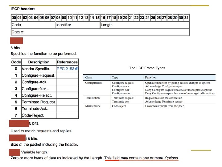
Link Control Protocol Three classes of LCP frames Configuration Termination Maintenance Configuration frame A pair of Configure-request and Configure-ack frames can open a connection The options such as the maximum receive unit or the authentication protocol are negotiable during the connection setup LCP frame is a special case of the PPP frame, we first introduce the PPP frame format before we look at the LCP frame format 92
The LCP Frame Types 93
Data Link Functions: Framing, Addressing, and Error Control The PPP frame is encapsulated in an HDLClike format The flag value is exactly the same as in HDLC It serves as the delimiter for framing PPP frame format 94
Differences between PPP and HDLC frame The address value is fixed at 1111, which is the all-stations address in the HDLC format Since only two peers are in a point-to-point link, there is no need to indicate an individual station address The control code has the fixed value 00000011, which corresponds to an unnumbered frame in the HDLC format This implies that by default, no sequence numbered and acknowledgement are used in the PPP [RFC 1663 defines an extension to make the PPP connection reliable]
A Protocol field is added to indicate which type of network layer protocol the frame is carrying, say IP or l. PX (Internetwork Packet Exchange, Novell) The default field length is 16 bits, but it can be reduced to 8 bits using the LCP negotiation The maximum length of the Information field, called the Maximum Receive Unit (MRU), is by default 1500 bytes. Other values for MRU are negotiable The default FCS is 16 bits long, but it can be extended to 32 bits through the LCP negotiation The receiver drops the received frame if an error is detected within the frame The responsibility of frame retransmission falls on the upper-layer protocols
Data Link Functions: No Flow Control and Medium Access Control Because PPP is full-duplex and only two stations are in a point-to-point link, no medium access control is needed for PPP On the other hand, PPP does not provide flow control, which is left to upper-layer protocols Chapter 3: Link Layer 39
LCP and NCP Negotiation The LCP frame is a PPP frame with the Protocol field value 0 xc 021, where 0 x stands for a hexadecimal number The negotiation information is embedded in the Information field as four main fields Code: indicate the LCP type Identifier: match requests and replies Length: indicate the total length of the four fields Data: carry the negotiation options
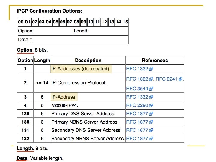
3. 2. 3 Internet Protocol Control Protocol IPCP is a member of NCP to configure IP over PPP first establishes a connection by LCP, and then uses NCP to configure the network layer protocol it carries After the configuration is done, the link is able to carry IP data as a payload of the PPP frame Chapter 3: Link Layer 41
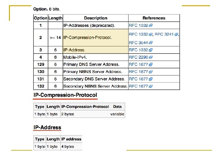
IPCP provides the configuration option [within Header / Data field] IP-Addresses: is obsolete and is replaced by “IP-Address” IP-Compression-Protocol: indicates the use of Van Jacobson's TCP/IP header compression IP-Address: allows the peer to provide an IP address to be used on the local end Chapter 3: Link Layer
After IPCP negotiation, normal IP packets can be transmitted over the PPP link by encapsulating IP packets in the PPP frame with the Protocol field value 0 x 0021 PPP frame format
3. 2. 4 PPP over Ethernet (PPPo. E) The Need for PPPo. E As Ethernet technology becomes cheap and dominant, it is common that users set up their own Ethernet LAN at home or in the office On the other hand, the broadband access technology, say ADSL, has become a common method to access the Internet from home or office Multiple users on an Ethernet LAN access the Internet through the same broadband bridging devices, so service providers desire a method to have access control and billing on a peruser basis, similar to conventional dial-up services Chapter 3: Link Layer 44
PPP is able to build the point-to-point relationship between peers, but an Ethernet network involves multiple stations PPP over Ethernet (PPPo. E) protocol Each individual station on a LAN can establish a PPP session with a remote PPPo. E server, which is located in the ISP and known as Access Concentrator (AC), through common bridging devices Each user on the LAN sees a PPP interface just like that seen in the dial-up service But the PPP frames are encapsulated in the Ethernet frames Through PPPo. E, the user’s computer obtains an IP address The ISP can easily associate the IP address with a specific user name and password 106
PPPo. E two-stage operation Discovery stage PPP session stage Discovery stage The user station discovers the MAC address of the access concentrator and establishes a PPPo. E session with the access concentrator; a unique PPPo. E session identifier is also assigned to the session Once the session is established, both peers enter the PPP session stage and do exactly what a PPP session does, say LCP negotiation 107
Discovery stage proceeds in the following four steps 1. The station to access the Internet broadcasts an Initiation frame to ask remote access concentrators to return their MAC addresses 2. The remote access concentrators reply with their MAC addresses 3. The original station selects one access concentrator and sends a Session-Request frame to the selected access concentrator 4. The access concentrator generates a PPPo. E session identifier and returns a Confirm frame with the session id 108
PPP session stage Runs in the same way as a normal PPP session does except only PPP frames are carried on Ethernet frames When the LCP terminates a PPP session, the PPPo. E session is torn down as well 109
New a PPPo. E session A new PPP session requires a new PPPo. E session starting from the Discovery stage Terminate a PPPo. E session A normal PPP termination process can terminate a PPPo. E session PPPo. E allows either the initiating station or the access concentrator to send an explicit Terminate frame to close a session Once the Terminate frame is sent or received, no further frame transmission is allowed 110
3. 3 Ethernet (IEEE 802. 3) Ethernet evolution: A big picture The Ethernet MAC 111
3. 3. 1 Ethernet Evolution: A Big Picture From low to high speed From shared to dedicated media From LAN to MAN and WAN The medium is getting richer Coaxial cables Twisted pairs Optical fibers Chapter 3: Link Layer 50
113
Milestones in Ethernet Standards 114
IEEE 802. 3 Physical Specifications 115
Summary of Standard Ethernet implementations 116
Summary of Fast Ethernet implementations 117
Summary of Gigabit Ethernet implementations 118
Summary of 10 -Gigabit Ethernet implementations 119
3. 3. 2 The Ethernet MAC Purposes Application • Data encapsulation, transmit, receive • Medium access management Presentation Higher layers Session Logical Link Control (LLC) Transport Data-link Physical LLC Network Link Aggregation (optional) MAC Control (optional) MAC sublayer Ethernet PHY OSI model Chapter 3: Link Layer 53
IEEE 802. 3 Ethernet MAC Frame Format Preamble This field synchronizes the physical signal timing on the receiver side Its value is fixed at 1010… 1010 in the transmission order, 56 bits long SFD This field indicates the start of the frame with the value 10101011 in the transmission order 121
DA This field includes the 48 -bit destination MAC address SA This field includes the 48 -bit source MAC address 122
Type/Length (T/L) The DIX (DEC-Intel-Xerox) standard specified this field to be a code of payload protocol type, say IP The IEEE 802. 3 standard specified this field to be the length of the data field 6 and left the protocol type to the LLC sublayer The 802. 3 standard later (in 1997) approved the type field, resulting in the dual interpretations of this field today 123
The way to distinguish Because the data field is never larger than 1500 bytes, a value less than or equal to 1500 means a length field and a value larger than or equal to 1536 (=0 x 600) means a type field The values in between are intentionally not defined 124
Data This field carries the data varying from 46 to 1500 bytes FCS This field carries a 32 -bit CRC code as a frame check sequence If the receiver finds an incorrect frame, it discards the frame silently The transmitter knows nothing about whether the frame is discarded 125
The responsibility of frame retransmission is left to upper-layer protocols such as TCP The error is not a big problem here because the bit error rate is assumed to be very low in the Ethernet physical layer The frame size is variable We often exclude the first two fields and say an Ethernet frame has the minimum length of 64 (=6+6+2+46+4) bytes and the maximum length of 1518 (=6+6+2+1500+4) bytes 126
Medium Access Control: Transmission and Reception Flow How a frame is transmitted and received inside the Ethernet MAC? CSMA/CD (Carrier Sense Multiple Access with Collision Detection) works in a simple way in MAC sublayer With a frame to transmit, CSMA/CD senses the cable first If a carrier signal is sensed, i. e. , the cable is busy, it continues sensing the cable until the cable becomes idle; otherwise, it waits for a small gap, and then transmits If a collision is detected during transmission, CSMA/CD jams the cable, aborts the transmission, and waits for a random back-off time interval before retrying 127
Frame Transmission and Reception 128
Frame Transmission Flow of CSMA/CD
(1) The MAC client (IP, LLC, etc. ) asks for frame transmission (2) The MAC sublayer prepends and appends MAC information (preamble, SFD, DA, SA, type, and FCS) to the data from the MAC client (3) In the half-duplex mode, the CSMA/CD method senses the carrier to determine whether the transmission channel is busy If so, the transmission is deferred until the channel is clear 130
(4) Wait for a period of time called inter-frame gap (IFG) The time length is 96 bit times for all Ethernet types The bit time is the duration of one bit transmission and thus is the reciprocal of the bit rate The IFG allows time for the receiver to do processing such as interrupts and pointer adjustment for incoming frames 131
Frame Transmission Flow of CSMA/CD
(5) Start to transmit the frame (6) In the half-duplex mode, the transmitter should keep monitoring if there is a collision during transmission The monitoring method depends on the attached medium Multiple transmissions on a coaxial cable result in higher absolute voltage levels than normal 133
(7) In case no collision is detected during transmission, the frame is transmitted until done If a collision is detected in the half-duplex mode, proceed with steps 8– 12 (8) The transmitter transmits a 32 -bit-long jam signal to ensure that the collision is long enough that all involved stations are aware of it The pattern of the jam signal is unspecified Common implementations are to keep transmitting 32 more data bits or to use the circuit that generates the preamble to transmit alternating 1’s and 0’s 134
Frame Transmission Flow of CSMA/CD
(9) Abort the current transmission and attempt to schedule another transmission (10) The maximum number of attempts to retransmit is 16 If still not able to transmit, abort the frame 136
(11) On an attempt to retransmit, a back-off time interval in units of slots is chosen randomly from the range of 0 to 2 k − 1, where k = min(n, 10) and n is the number of attempts The range grows exponentially, so the algorithm is referred to as truncated binary exponential back-off The duration of a time slot is 512 bit times for 10/100 Mbps Ethernet and 4096 bit times for 1 Gbps Ethernet (12) Wait the back-off time interval and then attempt to retransmit 137
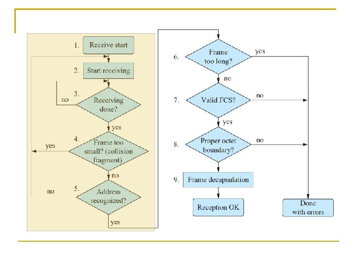
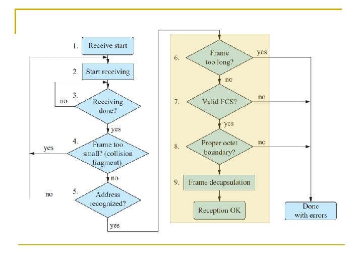
Frame Reception Flow of CSMA/CD Receiving a frame is much easier when a sequence of checks is done on the following items before passing it to the MAC client Frame length (check if the frame is too short or too long) Destination MAC address FCS (Frame Check Sequence) Octet boundary 138
(1) The arrival of a frame is detected by the physical layer of the receiver (2) The receiver decodes the received signal and passes the data, except the preamble and SFD, up to the MAC sublayer (3) The receiving process goes on as long as the received signal continues When the signal ceases, the incoming frame is truncated to an octet boundary (4) If the frame is too short (shorter than 512 bits), it is treated as a collision fragment and dropped (5) If the destination address is not for the receiver, the frame is dropped Chapter 3: Link Layer 59
(6) If the frame is too long, it is dropped and the error is recorded for management statistics (7) If the frame has an incorrect FCS, it is dropped and the error is recorded (8) If the frame size is not an integer number of octets, it is dropped and the error is recorded (9) If everything is OK, the frame is de-capsulated and the fields are passed up to the MAC client 142
Can Collision Cause Bad Performance? Collision cause a garbled frame, but it is not so bad if the transmission can be stopped when a collision is detected Where can a collision occur? 143
Where Can a Collision Occur? Collision detection with propagation delay 144
Where can an collision occurs? Suppose Station A transmits a minimum frame of 64 bytes, and the propagation time before the frame’s first bit arrives at station B is t Even with carrier sense, Station B is likely to transmit anytime before t and cause a collision 145
Further, suppose the worst-case scenario in which Station B transmits right at time t, which results in a collision The collision then takes another t to propagate back to station A If Station A finishes transmitting the minimum frame before the round-trip time 2 t expires, it has no chance to invoke collision detection and to schedule a retransmission, and thus the frame is lost
For CSMA/CD to function normally, the round-trip time should be less than the time required to transmit a minimum frame [catch time to notify collision], meaning the CSMA/CD mechanism limits the extent between two stations in a collision domain Because the minimum frame size is 64 bytes, it also means that a collision must occur during the first 64 bytes of a frame under the distance limitation If more than 64 bytes have been transmitted, the chance of collision has been ruled out due to carrier sense by other stations 147
Half-Duplex vs. Full-Duplex Half-duplex Only one station can transmit over common transmission channel (CSMA/CD needed) Full-duplex (IEEE 802. 3 x, 1997) Simultaneous transmission between a pair of stations with a point-to-point channel (no CSMA/CD) [no “multiple access” on a dedicated medium] 148
Three necessary and sufficient conditions for fullduplex Simultaneous transmission and reception without interference Dedicated point-to-point link with exactly two stations Both stations capable and configured in fullduplex mode 149
Flow Control in Ethernet Back pressure techniques – for half-duplex Ethernet False carrier If the receiver cannot afford more incoming frame, it can transmit a carrier, says a series of 1010… 10, on the shared medium until it can afford more frames The transmitter will sense the carrier and defer its subsequent transmission Force collision The congested receiver can force a collision whenever a frame transmission is detected, causing the transmitter to back off and reschedule its transmission Chapter 3: Link Layer 63
PAUSE frame – for full-duplex Ethernet The receiver explicitly sends a PAUSE frame to the transmitter, and upon receiving the PAUSE frame, the transmitter stops transmitting immediately The PAUSE frame carries a field, pause_time, to tell the transmitter how long it should halt its transmission Chapter 3: Link Layer 63
3. 5 Bridging Network administrators usually connect separate LANs into an interconnected network to extend a LAN or to improve it’s administration An interconnection device operating at the link layer is called a MAC bridge, or simply bridge Almost all bridges are transparent bridges because all stations on the interconnected LANs are unaware of their existence Chapter 3: Link Layer 102
3. 5. 1 Self-Learning Bridge operation: self-learning
How the bridge knows whether it should forward an incoming frame and to which port it should forward Bridge operation (self-learning) A bridge keeps an address table, also called forwarding table, to store the mapping of MAC addresses to port numbers Initially, the address table is blank, and the bridge knows nothing about the location of stations Suppose Station 1 with MAC address 00 -32 -12 -12 -6 d-aa transmits a frame to Station 2 with MAC address 00 -1 c-6 f-12 -dd -3 e Because Station 1 is connected to Port 3 of the bridge, the bridge will receive the frame from Port 3 By checking the source address field of the frame, the bridge learns the MAC address 00 -32 -12 -12 -6 d-aa is located on the segment to which Port 3 is connected, and then keeps the learned fact in the address table 154
However, it still does not know where the destination address 00 -1 c-6 f-12 -dd-3 e is located To ensure that the destination can receive the frame, it simply broadcasts the frame to every port except the port where the frame originates Suppose Station 2 transmits a frame to somewhere a moment later The bridge will learn that its address comes from Port 2 and will keep this fact in the address table as well Subsequent frames destined for Station 2 will be forwarded to Port 2 only, without broadcast 155
3. 5. 2 Spanning Tree Protocol As the topology of a bridged network becomes larger and more complex, network administrators may inadvertently create a loop in the topology This situation is undesirable because frames can circulate around the loop and the address table may become unstable Example Consider the following disaster in which two 2 -port switches form a loop and a station broadcasts a frame onto the loop Each switch will forward the broadcast frame to the other upon receiving it, making it circulate around the loop indefinitely IEEE 802. 1 D stipulates a spanning tree protocol (STP) to eliminate loops in a bridged network 156
Purpose: resolve loops in the bridged network RP: Root port DP: Designated port BPDU: Bridge Protocol Data Unit X X A bridged network with loops 157
STP procedural steps 1. Initially, each switch and port is assigned an identifier composed of a manageable priority value and switch address (or port number for port identifier) For simplicity, we use 1 to 6 as the identifiers in this illustration X X 158
1. Each link is specified a cost that can be inversely proportional to the link speed We assume all link costs are 1 here 2. The switch with the least identifier serves as the root X X The root is elected through the exchange of frames of configuration information among switches 159
4. Each LAN is connected to a port of some switch in an active topology The port through which the LAN transmits frames originating from the root is called the designated port (DP), and the switch is called the designated bridge X X The port through which the switch receives frames from the root is called the root port (RP) 160
4. Periodically, configuration information propagates downward from the root on the bridge protocol data unit (BPDU) whose destination address is a reserved multicast address for switches, 0180 -C 2 -00 -00 -00 X The BPDU frame contains information such as - the root identifier - the transmitting switch identifier - the transmitting port identifier - the cost of the path from the root X X X 161
5. Each switch may configure itself based on the information carried in the received BPDUs The configuration rules are (a) If the switch finds it can provide a lower path cost by comparing with the path cost advertised in BPDUs, it will attempt to be a designated bridge by transmitting BPDUs with its lower path cost X X 5. (b) In case of ambiguity, e. g. , multiple choices of equal path cost, the switch or port with the least identifier is selected as the designated bridge (port) 162
(c) If the switch finds it has a lower identifier than that of the current root, it will attempt to become the new root by transmitting BPDUs with its identifier as the root identifier X X (d) Note that a switch does not forward any incoming BPDUs, but may create new BPDUs to carry its new states to others X X 163
7. All ports other than DPs and RPs are blocked A blocked port is not allowed to forward or receive data frames, but it still keeps listening to BPDUs to see if it can be active again X X 164
3. 5. 3 Virtual LAN (VLAN) can provide for the logical configuration of LANs Administrators can simply work with management tools without changing the physical connectivity of the underlying network topology With VLAN separation, ports of a switch can be assigned to different VLANs, each functioning as a physically separated switch VLAN can be used to enhance network security and save bandwidth because traffic, particularly multicast and broadcast traffic, can be confined within a specifically defined VLAN to which the traffic belongs Chapter 3: Link Layer
For example A broadcast frame or a frame with an unknown unicast destination address will appear on all ports of a switch without VLAN such that not only does this frame consume bandwidth on unintended ports, but malicious users can monitor it as well By dividing the ports of a switch into several VLANs, the frame will be confined within a VLAN composed of the ports the frame is intended for 166
Consider we have two IP subnets: 140. 113. 88. 0 and 140. 113. 241. 0, each consisting of several stations If we want to connect these two IP subnets with a router, we may deploy the network in the manner depicted in the following figure Two-switch deployment without VLAN 167
If we configure the switch with two VLANs instead, only one switch is needed The router is connected to a port that belongs to two VLANs, and configured with two IP addresses, one for each subnet The router in this case is called the one-armed router With VLAN, administrators can arbitrarily group ports into several IP subnets, which is very convenient for network administration One-switch deployment with VLAN and one-armed router 168
IEEE 802. 1 Q standard Describe the architectural framework for VLAN in the aspects of Configuration Distribution of configuration information Allow the distribution of VLAN membership among VLAN-aware switches VLAN membership can be based on ports, MAC addresses, IP subnets, protocols, and applications Relay Classify and forward incoming frames, and the procedure to modify the frames by adding, changing, or removing tags 169
Each frame can be associated with a tag that bears a VLAN identifier so that the switch can quickly identify its VLAN association without complicated field classification A VLAN identifier has 12 bits, allowing a maximum number of 4094 (i. e. , 212– 2) VLANs, given that one identifier is reserved unused another is used to indicate a priority tag Format of a tagged frame. 170
Principle in Action: VLAN vs. Subnet VLAN Layer-2 concept, which allows network administrators to configure the connectivity at Layer 2 without physically rewiring VLAN is configured on a switch, a Layer-2 device Subnet Layer-3 concept. Hosts in a subnet can send packets to each other directly without the help of routers, including broadcast packets A subnet is configured by setting the IP addresses of the hosts with identical prefixes where the subnet mask determines the prefix length Chapter 3: Link Layer 117
C FI priority bits 3 VLAN identifier 1 12 Suggested mapping of priority values and traffic types 172
Priority Tag Priority field embedded in VLAN tag Preamble SF D DA SA VLAN protocol ID Tag control T/L 0 x 8100 Data C FI priority bits Format of a tagged frame. 3 high Suggested mapping of priority values and traffic types Chapter 3: Link Layer 12 000000 Traffic type 1 Background 2 Spare 0(default) VLAN identifier 1 Priority low FCS Best effort 3 Excellent effort 4 Controlled load 5 < 100 ms latency and jitter 6 < 10 ms latency and jitter 7 Network control 118
Link Aggregation Multiple links can be aggregated as if they were a pipe of larger capacity Example, users can aggregate two gigabit links into a single two-gigabit link if a larger link capacity is desired Aggregation operation is applicable to Links between switches Links between a switch and a station Links between two stations 174
Link aggregation principle The transmitter distributes frames among aggregated links The receiver collects these frames from the aggregated links Some difficulties complicate the design Example, consider the case in which several short frames follow a long frame If the long frame is distributed to one link and the short frames are distributed to another, the receiver might receive these frames out of order 175
Discussion Although an upper layer protocol such as TCP can deal with out-of-order frames, it is inefficient to do so The ordering of frames in a flow must be maintained in the link layer A flow may need to be moved from one link to another for load-balancing or because of link failure To meet these requirements, a link aggregation control protocol (LACP) is designed (IEEE 802. 3) 176