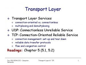
Computer Networks 2 The Transport Layer 1232020 Veton


![Client Unix Based Program: o o o Argv[1] contains server’s name (flits. cs. vu. Client Unix Based Program: o o o Argv[1] contains server’s name (flits. cs. vu.](https://slidetodoc.com/presentation_image_h/db90c261e40cf00d6872a6bcc6f68821/image-22.jpg)


- Slides: 53

Computer Networks 2 The Transport Layer 12/3/2020 Veton Këpuska 1

The Transport Layer o o It is the heart of the whole protocol hierarchy. Its task is to provide: n n n o Efficient Reliable Cost-effective, data transport from source machine to the destination machine Details of Transport Layer covered: n n 12/3/2020 Services Design Protocols Performance Veton Këpuska 2

The Transport Service o o o Transport Layer Provides Services to Application Layer. Kind of service provided to Application layer will be presented next. Services Provided to the Upper Layers: n n 12/3/2020 Efficient, Reliable, and cost-effective service to its users (typically processes in the application layer). To achieve this goal Transport Layer makes use of services provided by Network Layer. Veton Këpuska 3

Services Provided to the Upper Layers: o o Transport Entity: Hardware and/or Software within transport layer that does the work. It can be located in: n n o Operating System Kernel Separate User Process Library Package for Network Applications Network Interface card. Relationship of Network, Transport and Application Layers is illustrated in the next Figure. 12/3/2020 Veton Këpuska 4

The Network, Transport and Application Layer 12/3/2020 Veton Këpuska 5

Types of Transport Service o o Connection-Oriented Service Connectionless-Oriented Service Both services have 3 phases: n Establishment n Data Transfer n Release Those services are similar to corresponding Network layer services. They are similar in: n Addressing, and n Flow Control 12/3/2020 Veton Këpuska 6

The Transport Service o If the services of Transport layer are similar to Network layer services then why there are those two distinct layers in network protocol architecture? 2. Transport Layer runs entirely on the users machines. Network Layer mostly runs on the routers (Operated by Carriers). n What happens if Network Layer offers inadequate Service? 1. o o Frequently lost packets. Routers crashes, etc. => Problems in delivery and communication. Transport layer has to deal with those problems without having real control over the network layer: n It can not resort to improving the service by using: o o 12/3/2020 Better Routers, More robust error handling of Data Link Layer, etc. Veton Këpuska 7

The Transport Service o Transport Entity - in connection-oriented subnet: n If a transmission has been abruptly terminated halfway, and n There is no indication of what has happened to the data currently in transit, then transport service can: n n n 12/3/2020 Setup up a new network connection to the remote transport entity. Send a query to its peer asking which data arrived and which did not. It can pick up from where it left off. Veton Këpuska 8

The Transport Service o Transport Layer makes possible for Transport Service to be more reliable than underlying Network Layer Services. n n o Transport Service Primitives can be implemented as Calls to Library Procedures: n n o Lost Packets and Corrupted Data can be detected and compensated for by the transport layer. This is done with Transport Service Primitives Hide Network Service Calls. Provide uniform interface to underlying different network services and protocols. Application Programmers thus can: n n Write code according to a standard set of primitives, Ignore the details of wide variety of: o o o 12/3/2020 Networks Interfaces, and Unreliable transmissions. Veton Këpuska 9

The Transport Service o If all real network were n n o Since this can not be the case: Transport layer fulfills the key function of isolating the upper layers from the: n n n o Technology Design, and Imperfections of subnets. First 4 layers are considered: n o Flawless, and Had the same service primitives, and Services were guaranteed never to change: Transmission layer might not be needed. Transport Service Provider Upper 4 Layers are considered: n 12/3/2020 Transport Service User Veton Këpuska 10

Transport Service Primitives o o o Access to Transport Service is provided to application programs through transport service interface. Each Transport Service has its own interface via a set of Transport Service Primitives. Processes (Applications) using Transport Service Primitives expect that connection between them to be perfect. 12/3/2020 Veton Këpuska 11

Primitives for a Simple Transport Service o Fig 6 -2. Primitives for a simple transport services. 12/3/2020 Veton Këpuska 12

Example of Usage of Transport Service Primitives o o Consider Application with a Server and a number of remote Clients. Server initially executes LISTEN primitive. n o o When a Client wants to talk to the Server, it executes CONNECT primitive. The transport entity carries out this primitive by blocking the caller and sending a packet to the server. Messages send from transport entity to another transport entity are called TPDU (Transport Protocol Data Unit). n n o This function call typically is done to a library procedure which in turn makes a system call to block the server until a client turns up. TPDU’s are contained in Network Packets in turn are contained in Data Link Frames. Nesting of TPDUs, packets and frames (Fig 6 -3): 12/3/2020 Veton Këpuska 13

Transport Service Primitives o o Client’s CONNECT call causes a CONNECTION REQUEST TPDU to be sent to the Server. Transport Entity in the Server n n o When connection accepted TPDU arrives at the Client: n n o Checks if Server is blocked on a LISTEN mode (ready to handle requests). Unblocks the Server and sends a CONNECTION ACCEPTED TPDU back to the Client is unblocked, and Connection is Established. Data can now be exchanged using SEND and RECEIVE primitives. n 12/3/2020 In the simplest form either party can do RECEIVE to wait for the other party to do a SEND. When TPDU arrives the receiver is unblocked. It then can process the TPDU and send a reply. Veton Këpuska 14

Transport Service Primitives o At the Transport Layer, even a simple unidirectional data exchange is more complicated than at the network layer. n Every data packet send will also be acknowledged. n Control TPDU packets are also acknowledged implicitly or explicitly. n n o Acknowledgments are Managed by the transport entities using the network layer protocol, and are Transport entities also need to worry about timers and retransmissions. All these mechanisms are NOT visible to the transport users. 12/3/2020 Veton Këpuska 15

Transport Service Primitives o o Termination of a Connection: When existing connection is no longer needed it must be released to free up tables from two transport entities. Disconnection can e done in two possible variants: n Asymmetric: either of transport entities can issue DICONNECT TPDU and send to a remote transport entity. Upon arrival the connection is released. n Symmetric: each direction is closed separately and independently of the other one. In this variant connection is released only when both sides have done a DISCONNECT. 12/3/2020 Veton Këpuska 16

Berkeley Sockets o o o Another set of Transport Primitives are socket primitives in Berkeley UNIX for TCP. Those primitives are widely used for Internet Programming. Figure 6 -5. The socket primitives for TCP. 12/3/2020 Veton Këpuska 17

Berkeley Sockets o SERVER: n SOCKET, BIND, LISTEN, ACCEPT – are executed in that order by a Server. o SOCKET: Creates a new end point and allocates table space for it within the transport entity. n n o o o BIND: New Sockets do not have network address. These are assigned using the BIND primitive. Once server has bound an address to a socket, remote clients can connect to it. LISTEN: is a primitive which allocates space to queue incoming calls in case that several clients try to connect at the same time. In contrast to LISTEN primitive of the first example, socket model of LISTEN is not a blocking primitive. ACCEPT: is a blocking primitive that server executes to block wait for an incoming connection. n n n 12/3/2020 The parameters of the call specify: § Addressing format to be used § Type of service desired , and § Protocol. Return of a call is an ordinary file descriptor to be used in succeeding calls (just like OPEN call does). When a TPDU asking for a connection arrives, the transport entity creates a new socket with the same properties as the original and returns a file descriptor for it. The server can then fork off a process or thread to handle the connection on the new socket and go back to waiting for the next connection on the original socket. ACCEPT returns a normal file descriptor, which can be used for reading and writing in the standard way, the same as for files. Veton Këpuska 18

Berkeley Sockets o CLIENT: n n n SOCKET: is used to create a socket. BIND: is not required since the address used does not matter to the server. CONNECT: blocks the caller and actively starts the connection process. o When this process is complete – that is when appropriate TPDU is received from the server: n n n 12/3/2020 Client process is unblocked, and Connection is established. Both sides can use SEND and RECV to transmit and receive data over the full-duplex connection. In addition if none of special options of SEND and RECV are required, standard UNIX system calls READ and WRITE can be used. Connection release with sockets is symmetric. When both sides execute CLOSE primitive the connection is released. Veton Këpuska 19

An Example of Socket Programming: An Internet File Server. o o http: //www. prenhall. com/tanenbaum Compilation: n n o cc –o client. c –lsocket -lnsl cc –o server. c –lsocket -lnsl Execution: n n 12/3/2020 server client flits. cs. vu. nl /usr/tom/filename > f Veton Këpuska 20

Server Unix Based Program o o Server Port: arbitrarily chosen number (valid range 1024 – 65545). Chosen port number can not be use by other process. Client and Server must use the same port #. BUF_SIZE: chunk size used for file transfer. QUEUE_SIZE: number of pending connections held before additional ones are disregarded. 12/3/2020 Veton Këpuska 21
![Client Unix Based Program o o o Argv1 contains servers name flits cs vu Client Unix Based Program: o o o Argv[1] contains server’s name (flits. cs. vu.](https://slidetodoc.com/presentation_image_h/db90c261e40cf00d6872a6bcc6f68821/image-22.jpg)
Client Unix Based Program: o o o Argv[1] contains server’s name (flits. cs. vu. nl) and is converted to an IP address by gethostbyname. This look up uses DNS (Domain Name System). After client creates a socket it attempts to establish a TCP connection to the server using connect. If the server is up and running on the named machine and attached to SERVER_PORT and is either idle or has room it its listen queue, the connection will eventually be established. 12/3/2020 Veton Këpuska 22

Elements of Transport Protocols o o Transport Service is implemented by a Transport Protocol (used between the two transport entities). Similarities of Transport Protocols with Data Link Protocols; both have to deal with: n n n o Error Control, Sequencing, Flow Control, etc. Dissimilarities of Transport Protocols and Data Link Protocols are due to major dissimilarities between environments in which the two protocols operate (Figure 67). n n n 12/3/2020 Data Link Protocol applies to direct communication of two routers via a physical channel. Transport Layer Protocol operates on the level of an entire subnet. This distinction has many important implications for the Transport Layer protocols. Veton Këpuska 23

Elements of Transport Protocols a) b) Environment of the data link layer. Environment of the transport layer 12/3/2020 Veton Këpuska 24

Elements of Transport Protocols Destination Address 1. In Data Link Layer, router does not necessarily need to specify which router it wants to talk-to; each outgoing line uniquely specifies a particular router. In Transport Layer explicit addressing of destinations is required. o o Initial Connection 2. Process establishing connection over the wire is simple: the other end is always there unless has crashed. In either case there is not much to do. In transport layer initial connection establishment is more complicated. o o Communication Protocol to handle Potential Existence of Storage Capacity in the Subnet. 3. When a router sends a frame: o • • It may arrive, or It is lost. Either way it cannot bounce around for a while, go into hiding and bounce back after 30 sec later. If the subnet uses datagrams and adaptive routing there is nonnegligible probability that a packet may be stored for a number of seconds and then delivered later. This requires special protocols to deal with this issue. o o Buffer size allocation for Flow Control 4. o o 12/3/2020 In data link layer commonly has a fixed number of buffers for each line is allocated so that when frame arrives a buffer is always available. In transport layer due to large number of connections that must be managed make the idea of dedicating many buffers to each one less feasible. Veton Këpuska 25

Addressing o o o When application process sets up connection to a remote application process, it must specify which process to connect to. The method normally used is to define transport addresses to which processes can listen for connection requests. These end points in n n o Internet are called ports. ATM they are called AAL-SAP (ATM Adaptive – Service Access Point). Generic term for Transport Layer: TSAP (Transport Service Access Point), and Analogous end points in network layer (i. e. , network layer addresses) are called NSAPs. IP addresses are examples of NSAP. Figure 6 -8 illustrates the relationship between the NSAP, TSAP and transport connection 12/3/2020 Veton Këpuska 26

Addressing o o Application Processes (both Clients and Servers) can attach themselves to a TSAP to establish a connection to a remote TSAP. o TSAPs, NSAPs and Transport Connection These connections run through NSAPs on each host (as shown in the figure). TSAPs are required because in some networks each computer has a single NSAP, thus a mechanism is needed to distinguish multiple transport end points that share that particular NSAP. A possible scenario for transport connection is given in the next slide. 12/3/2020 Veton Këpuska 27

Addressing 1. A time of day server process on host 2 attaches itself to TSAP 1522 to wait for incoming call. A call such as LISTEN might be used. (Note that how a process attaches itself to a TSAP is outside the networking model and depends entirely on the local operating system). 2. An application on host 1 wants to find out the time-of-day, so it issues a CONNECT request specifying TSAP 1208 as the source and TSAP 1522 as the destination. This action ultimately results in a transport connection being established between the application process on host 1 and server 1 on host 2. 3. The application processes then sends over a request for the time. 4. The time server process responds with the current time. 5. The transport connection is then released. 12/3/2020 o Veton Këpuska TSAPs, NSAPs and Transport Connection 28

Addressing o Note: n n 12/3/2020 o TSAPs, NSAPs and Transport Connection There may be other servers on host 2 that are attached to other TSAPs and waiting for incoming connections that arrive over the same NSAP. Second issue is: How does the user process on host 1 know the time -of-day server is attached to TSAP 1522? Veton Këpuska 29

Addressing o Possible solution: n n n 12/3/2020 Established conventions – time-of-day server has been attaching itself to TSAP 1522 for years and gradually all the network users have learned this. In this model, services have stable TSAP addresses that are listed in files in well-know places, such as the /etc/services file on UNIX systems which lists which servers are permanently attached to which ports. Stable TSAP addresses work for small number of key services that never change. Users processes, in general, often want to talk to other user processes that only exist for a short time and do not have a TSAP address that is known in advance. It is wasteful to have each of server processes to be active and listen to a stable TSAP address of their own if there are many such processes and most of which are rarely used. A better scheme (see Fig. 6 -9) know as initial connection protocol is used. Veton Këpuska 30

Initial Addressing Protocol o How a user process in host 1 establishes a connection with a time-of-day server in host 2. 12/3/2020 Veton Këpuska 31

Initial Connection Protocol o o Instead of each conceivable server listening at well-know TSAP, each machine that wishes to offer services to remote users has a special process server that acts as a proxy for less heavily used servers. Process Server listens to a set of ports at the same time waiting for CONNECT request specifies the TSAP address of the service they want. If no server is waiting for them, they get process server. Process Server then spawns the requested server, allowing to inherit the existing connection with the user. n n o o New server does the requested work. Process Server goes back to listening for new requests. There are many situations in which services do need to exist independently of Process Server (e. g. , file server can not be created on the fly when one wants to talk to it). An alternative scheme is to use a special process called a name server/directory server (equivalent to directory assistance). 12/3/2020 Veton Këpuska 32

Initial Connection Protocol o To find a TSAP address corresponding to a given service name (e. g. , time of day) a user sets up a connection to the name server (which listens to a well-know TSAP). n User sends a message specifying the service name. n Server sends back the TSAP address. n Users releases connection with name server and establishes a new connection with desired service. n This method requires registering of created new service with the name server containing service name and corresponding TSAP. 12/3/2020 Veton Këpuska 33

Connection Establishment o Why establishing a connections is not easy? Problems occur when the network can lose, store, and duplicate packets. This behavior causes serious complications. n Assume a subnet that is so congested that: o o n Worst possible scenario: o o o o Acknowledgments hardly ever get back in time, and Each packets times out and is retransmitted two or three times. Subnet uses datagrams and thus every packets follows a different route. Some of the packets get stuck in a traffic jam inside the subnet and take a long time to arrive; they are stored in the subnet and pop out much later. A user establishes a connection with a bank, Sends messages telling the bank to transfer a large amount of money to the account of a “notentirely-trustworthy” person. Releases the connection. Each packet in this scenario is duplicated and stored in the subnet. After the connection has been released, all the packets pop out of the subnet and arrive at the destination in order – asking the bank to establish anew connection, transfer money (again) and release the connection. The bank has no way of telling that this is a duplicate. Thus it must assume that this is a second independent transaction, and transfers the money again. In the remainder of this section the problem of delayed duplicates with special emphasis on algorithms for establishing connections in a reliable way will be presented, so that scenarios like above do not happen. 12/3/2020 Veton Këpuska 34

Connection Establishment o o o The heart of the problem is the existence of delayed duplicates. Solution is based on killing off the aged packets that are still hobbling about. Ensuring that no packet lives longer than some known time. This way the problem becomes more manageable. Packet lifetime can be restricted to a know maximum using one (or more) of the following techniques: 1. 2. 3. 12/3/2020 Restricted subnet design. This approach includes any method that prevents packets from looping, combined with some way of bounding congestion delay over the longest possible path. Putting a hop counter in each packet. This method consists of having the hop count initialized to some appropriate value and decremented each time the packet is forwarded. The network protocol simply discards any packet whose hop counter becomes zero. Time-stamping each packet. This method requires the router clocks to be synchronized (which in itself is not a trivial task unless synchronization is achieved external to the network – e. g. GPS or some radio station that broadcasts the precise time periodically) Veton Këpuska 35

Connection Establishment o o o In addition to guaranteeing elimination of timed out packets, all associated acknowledgement packets also must be killed. In order to ensure elimination of undesirable duplicate packets; a time T is introduced that denotes a value that is a small multiple of the packets true maximum lifetime. This value T is protocol dependent and simply has the effect of making T longer. If transport entity waits a time T after a packet has been sent, it can be sure that all traces of it are now gone and that neither it nor its acknowledgement will suddenly appear out of the blue. 12/3/2020 Veton Këpuska 36

Three Protocol Scenarios for Establishing a Connection using a three-way handshake. o o With packet lifetime bounded, it is possible to devise a foolproof way to establish connections safely. Three-way handshake: Three possible scenarios presented in the figure are discussed next. 12/3/2020 Veton Këpuska 37

Connection Establishment o Three-way hand shake Protocol - Normal setup procedure when host 1 initiates connection is shown in Fig. 6 -11(a): n Host 1 chooses a sequence number, x, and send a CONNECTION REQUEST TPDU containing it to Host 2. n Host 2 replies with an ACK TPDU acknowledging x and announcing its own initial sequence number, y. n Host 1, acknowledges host 2’s choice of an initial sequence number in the first data TPDU that it sends. 12/3/2020 Veton Këpuska 38

Connection Establishment o o Old duplicate appearing out of nowhere (Fig. 6 -11(b)). The first TPDU is a delayed duplicate CONNECTION REQUEST from an old connection. n n n 12/3/2020 Delayed duplicate CONNECTION REQUEST arrives at host 2 without host 1’s knowledge. Host 2 reacts to this TPDU by sending host 1 an ACK TPDU, in effect asking for verification that host 1 was indeed trying to set up a new connection. When host 1 rejects host 2’s attempt to establish a connection, host 2 realizes that it was tricked by a delayed duplicate and abandons the connection. Veton Këpuska 39

Connection Establishment o Worst case scenario is when both delayed CONNECTION REQUEST and an ACK are floating around in the subnet. This case is shown in Fig. 6 -11(c). n n n 12/3/2020 Delayed duplicate CONNECTION REQUEST arrives at host 2 without host 1’s knowledge. Host 2 reacts to this TPDU by sending host 1 an ACK TPDU, in effect asking for verification that host 1 was indeed trying to set up a new connection. In addition Host 2 has proposed using y as the initial sequence number from host 2 to host 1 traffic, knowing full well that no TPDU’s containing sequence number y or acknowledgments to y are still in existence. When the second delayed TPDU arrives at host 2, the fact that z has been acknowledged rather than y tell host 2 that this too, is an old duplicate. Veton Këpuska 40

Connection Release o Asymmetric release (this is how telephone system works) n 12/3/2020 o Abrupt disconnection with loss of data. My cause loss of data. Veton Këpuska 41

Connection Release o Symmetric Release: n n n 12/3/2020 a) Normal case of three-way handshake. There is no full proof solution Three way hand-shake adequate solution User sends DR (DISCONNECTION REQUEST) TPDU to initiate connection release and starts its timer. Recipient sends back a DR TPDU as well and starts its timer. When original sender receives DR it sends back ACK TPDU and releases connection. Finally when ACK TPDU arrives and the recipient (host 2) the receiver also releases the connection. Veton Këpuska 42

Connection Release o Symmetric Release: n 12/3/2020 Scenario when final ACK TPDU is lost Veton Këpuska 43

Connection Release o Symmetric Release: n 12/3/2020 Scenario when Response TPDU from Receiving host is lost. Veton Këpuska 44

Connection Release o Symmetric Release: n n n 12/3/2020 Scenario when: o Response TPDU from Receiving host is lost, and o Repeated retransmit the DR also fail due to lost TPDUs. After N retries the sender just gives up and releases the connection, and Receiver times out and also exits. Veton Këpuska 45

Connection Release o Symmetric Release Failure Scenario: n n 12/3/2020 If initial DR and all of N retransmission attempts fail due to the loss of TPDU’s the protocol will fail because receiver can not release the connection because it has not received DR request. o Sender is not allowed to give up after N retries => it can go on forever until it gets a response. o If the other (receiving) side is allowed to time out, the sender will indeed go on forever because no response will ever be forthcoming. o If we do not allow the other (receiving) side to time out then the protocol hangs. One way to kill of half-open connections is to have a rule saying that if no TPDUs have arrived for a certain number of seconds, the connection is then automatically disconnected. This way if one side ever disconnects, the other side will detect the lack of activity and also disconnect. Veton Këpuska 46

Flow Control and Buffering o Flow Control in Transport layer is in some ways similar to Data Link layer flow control but in others quite different. n n 12/3/2020 Main Similarities: o A sliding window or other scheme is needed on each connection to keep a fast transmitter form overrunning a slow receiver. Main Differences: o Router has very few lines, vs. o Host may have numerous connections. Veton Këpuska 47

Flow Control and Buffering o In Data Link layer: n o The sending side must buffer outgoing frames because they might have to be retransmitted. In Transport Layer: n n If the subnet provides datagram service, the sending transport entity must also buffer the TPDUs because they may have to be retransmitted (just like in data link layer). Receiver, if it knows that the sender buffers all TPDU’s until they are acknowledged, may or may not dedicate specific buffers to specific connections as it sees fit. o o o 12/3/2020 When a TPDU comes in an attempt is made to dynamically acquire a new buffer. If one is available the TPDU is accepted; otherwise it is discarded. Since the sender is prepared to retransmit TPDUs lost by the subnet no harm is done by having the receiver drop TPDUs (some resources are wasted). Sender keeps retransmitting until it gets an acknowledgment. Veton Këpuska 48

Flow Control and Buffering o Buffering: n If the network service is unreliable: o n With reliable network service other tradeoffs are possible: o o o 12/3/2020 The sender mast buffer all TPDUs sent. Sender may not retain copies of the TPDUs it sends if receiver always had buffer space for incoming TPDUs. If Receiver cannot guarantee that every incoming TPDY will be accepted the Sender will have to buffer anyway. The sender cannot trust the network layer’s acknowledgment, because the acknowledgment means only that the TPDU arrived, not that it was accepted. Veton Këpuska 49

Flow Control and Buffering o Buffer Size and Organization Issue: n n n 12/3/2020 a) b) If most TPDUs are nearly the same size buffers can be organized as: o A pool of identically-sized buffers, and o One TPDU per buffer (Fig. 615 (a)). If TPDUs vary in size significantly then the buffers can be organized as a chain of variable length buffers. o Better memory utilization o More complicated buffer management. Single large Circular buffer per connection. o Good memory utilization if all connections are heavily loaded o Poor memory utilization if some connections are lightly loaded. c) Veton Këpuska Chained fixed-size buffers Chained variable-sized buffers One large circular buffer per connection. 50

Flow Control and Buffering o Optimum trade-off between source buffering and destination buffering depends on the type of traffic carried by the connection. n For low-bandwidth bursty traffic, such as that produced by an interactive terminal it is better not to dedicate any buffers but rather to acquire them dynamically at both ends. o n For file transfer and other high-bandwidth traffic, it is better if the receiver does dedicate a full window of buffers, to allow the data to flow at maximum speed. o 12/3/2020 Better to Buffer at the Sender Better to Buffer at the Receiver Veton Këpuska 51

Flow Control and Buffering o When buffer space no longer limits the maximum flow, another bottleneck will appear: n Subnets carrying capacity: o o 12/3/2020 If adjacent routers can exchange at most x packets/sec and there are k disjoint paths between a pair of hosts, maximal rate of data transfer between those two routers is kx TPDUs/sec no matter how much buffer space is available at each end. If the sender transmits to fast (i. e. , sends more than kx TPDUs/sec), the subnet will become congested because it will be unable to deliver TPDUs fast enough. A mechanism is needed based on the subnet’s carrying capacity rather than on the receiver’s buffering capacity. Clearly flow control has to be applied to the sender to prevent it from having too many unacknowledged TPDUs outstanding at once. Solution: Sliding Window Flow Control Scheme Veton Këpuska 52

Flow Control and Buffering o Sliding Window Flow Control Scheme n Sender dynamically adjust the window size to match the network's carrying capacity. n Network can handle c TPDUs/sec Cycle Time is r (it includes transmission, propagation, queuing, processing at the receiver, and return of the acknowledgement). Senders window should be c*r n Adjustment of the window size: n n o o o 12/3/2020 Carrying capacity can be determined by simply counting the number of TPDUs acknowledged during some time period and then dividing by that time period. During the measurement sender should send as fast as it can, to make sure that the network’s carrying capacity and not the low input rate is the factor limiting the acknowledgment. The time required for transmitted TPDU to be acknowledged can be measured exactly and a running mean can be maintained. Veton Këpuska 53
 Positional traction
 Secure socket layer and transport layer security
 Secure socket layer and transport layer security
 Secure socket layer and transport layer security
 Secure socket layer and transport layer security
 Datagram approach
 Backbone networks in computer networks
 Data link layer switching
 O s i reference model ka chitra
 The network layer concerns with
 Elementary data link protocols in computer networks
 Data link control
 Network layer design issues
 Internet transport protocol in computer networks
 Hidden markov chain
 Lpc matlab code
 Veton kepuska
 Algebra
 Louse veton
 Kpuska
 Veton kepuska
 Kpuska
 A link layer protocol for quantum networks
 Greedy layer wise training of deep networks
 Pigmented layer and neural layer
 Git layers
 Presentation layer functions
 Layer 2 e layer 3
 Layer-by-layer assembly
 Layer 2 vs layer 3 bitstream
 Transport layer handles multiplexing and demultiplexing
 Layer 2 transport
 Principles of reliable data transfer in transport layer
 Crash recovery in transport layer geeksforgeeks
 Upward multiplexing
 Chapter 3 transport layer
 Wireless transport layer security
 Rdt 3.0 receiver fsm
 Reliable data transfer in transport layer
 Multiplexing and demultiplexing in transport layer
 Dns transport layer protocol
 Transport layer
 Mobile transport layer
 Transport layer
 Transport layer primitives
 Transport layer
 Transport layer
 Transport layer
 Iup handshake
 Design goals of transport layer protocol
 Multiplexed transport layer security
 Transport layer
 Transport layer ppt
 Transport layer.


