Computer Microoperations n n A microoperation is an


 n Is to physically connect all of the control")


 n uses software for control, and is illustrated in Figure")


- Slides: 26
Computer Microoperations n n A microoperation is an elementary operation performed with the data stored in registers. The microoperations most often encountered in digital computers are classified into four categories: 1 - Register transfer microoperations: transfer binary information from one register to another. 2 - Arithmetic microoperations: perform arithmetic operations on numeric data stored in registers. 3 - Logic microoperations: perform bit manipulation operations on non- numeric data stored in registers. 4 -Shift microoperations: perform shift operations on data stored in registers.
Basic arithmetic microoperations l l n n Addition Increment * Subtraction * Decrement Add microoperation R 3 R 1 + R 2 To implement this statement with hardware we need three registers and the digital component that performs the addition operation Subtraction is most often implemented through complementation and addition. Instead of using the minus operator, we can specify the subtraction by the following statement: R 3 R 1 + R 2/ + 1
Arithmetic Microoperations
Binary Adder n To implement the add microoperation with hardware, we need the registers that hold the data and the digital component that performs the arithmetic addition. n n n A full-adder is the digital circuit that forms the arithmetic sum of two bits and a previous carry. A binary adder is the digital circuit that generates the arithmetic sum of two binary numbers of any lengths. Binary Adder-Subtractor
Arithmetic Circuit Implementation
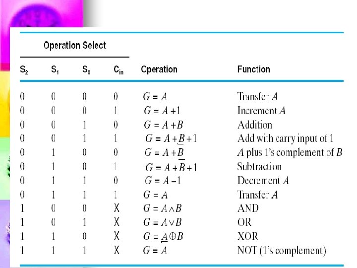
Functions performed by the circuit Select S 1 S 0 Cin 0 0 0 Input Y B Output D=A+Y+ Cin D=A+B microoperation 0 0 1 B D=A+B+1 0 B/ D=A+B/ 0 1 1 B/ D=A+B / +1 1 0 0 0 D=A Transfer A 1 0 D=A+1 Increment A 1 1 0 1 D=A-1 Decrement A 1 1 D=A Transfer A Add with carry Subtract with borrow Subtract
When all 1’s are inserted into the Y inputs n A number with all 1’s is equal to the 2’s complement of 1 (the 2’s complement of binary 0001 is 1111). n Adding a number A to the 2’s complement of 1 produces F = A + 2’s comp. of 1 = A - 1. (decrement) n When Cin= 1, then D = A - 1 + 1= A, n
Logic Microoperations
n n n The + symbol has two meanings; it will be possible to distinguish between them by noting where the symbol occurs. When the symbol + occurs in a microoperation, it will denote an arithmetic plus. When it occurs in a control (or Boolean) function, it will denote an OR operation For example, n P + Q: R 1 R 2 + R 3, R 4 R 5 V R 6 n The + between P and Q is an OR operation between two binary variables of a control function. The + between R 2 and R 3 specifies an add microoperation. The OR microoperation is designated by the symbol V between registers R 5 and R 6. n n
Hardware Implementation of logic microperations n n It requires that logic gates be inserted for each bit or pair of bits in the registers to perform the logic function. Although there are 16 logic microoperations, most computers use only four—AND, OR, XOR (exclusive-OR), and complement— from which all others can be derived.
Shift Microoperations Used for serial transfer of data. n They are also used in conjunction with arithmetic, logic, and other data-processing operations. n The contents of a register can be shifted to the left or the right. n There are three types of shifts: n a) Logical b) circular c) arithmetic
Symbolic designation Description R shl R Shift-left register R R shr R Shift-right register R R cil R Circular shift-left R R cir R Circular shift-right R R ashl R Arithmetic shift-right R R ashr. R Arithmetic shift-right R
An arithmetic shift: n Is a microoperation that shifts a signed binary number to the left or right. n An arithmetic shift-left multiplies a signed binary number by 2. n An arithmetic shift-right divides the number by 2. Notes: n Arithmetic shifts must leave the sign bit unchanged because the sign of the number remains the same when it is multiplied or divided by 2. R n-1 Sign bit R n-2 R 1 R 0
Hardware Implementation of logic microperations
Arithmetic-Logic-Shift Unit n n n Instead of having individual registers performing the microoperations directly, computer systems employ a number of storage registers connected to a common operational unit called an arithmetic logic unit, abbreviated ALU. To perform a microoperation, the ALU performs an operation and the result of the operation is then transferred to a destination register. The arithmetic, logic, and shift circuits introduced in previous sections can be combined into one ALU with common selection variables.
S 3 S 2 S 1 Ci S 0 one stage of arithmatic circuit Di select 0 1 2 3 Ci+1 Bi Ai Ai-1 Bi-1 one stage of arithmatic circuit Ei shr shl 4 X 1 MUX
A DISCUSSION ON DECODING: HARDWIRED VS. MICROPROGRAMMED CONTROL n n n In reality, there must be control signals to assert lines on various digital components to make things happen as described. For example, when we perform an Add instruction in assembly language, we assume the addition takes place because the control signals for the ALU are set to “add” and the result is put into the AC. The ALU has various control lines that determine which operation to perform. The question we need to answer is, “How do these control lines actually become asserted? ” You can take one of two approaches to ensure control lines are set properly.
The first approach (hardwired control) n Is to physically connect all of the control lines to the actual machine instructions. n The instructions are divided up into fields, and different bits in the instruction are combined through various digital logic components to drive the control lines.
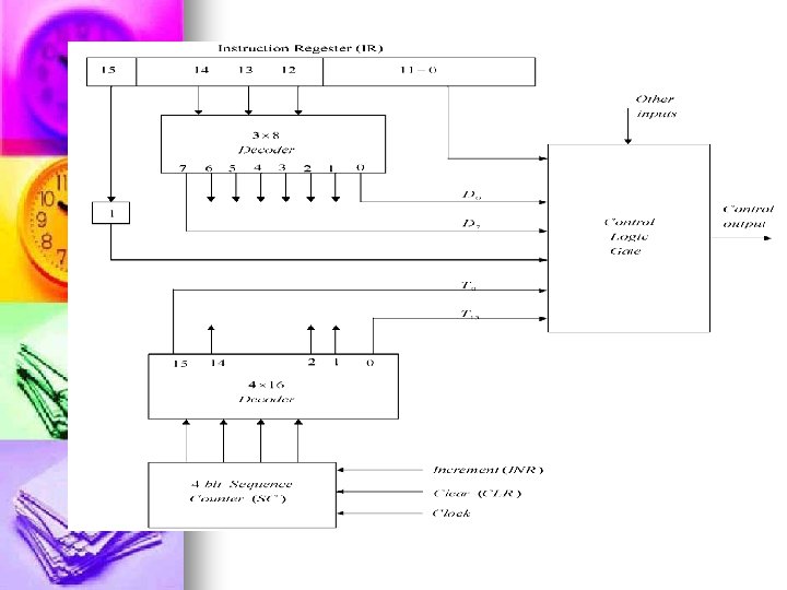
For example: A 4 -to-16 decoder could be used to decode the opcode. n By using the contents of the IR register and the status of the ALU, this unit controls the registers, the ALU operations, all shifters, and bus access. n
n ●The advantage of hardwired control is that it is very fast. n ●The disadvantage is that the instruction set and the control logic are directly tied together by special circuits that are complex and difficult to design or modify. n If someone designs a hardwired computer and later decides to extend the instruction set, the physical components in the computer must be changed. This is prohibitively expensive, because not only must new chips be fabricated but also the old ones must e located and replaced.
The Second approach (microprogramming) n uses software for control, and is illustrated in Figure n All machine instructions are input into a special program, the microprogram, to convert the instruction into the appropriate control signals. n The microprogram is essentially an interpreter, written in microcode, that is stored in firmware (ROM, PROM, or EPROM), which is often referred to as the control store. n This program converts machine instructions of zeros and ones into control signals. n Essentially there is one subroutine in this program for each machine instruction.
n The advantage of this approach is that: n If the instruction set requires modification, the microprogram is simply updated to match—no change is required in the actual hardware. n Microprogramming is flexible, simple in design, and lends itself to very powerful instruction sets. n Microprogramming allows for convenient hardware/software tradeoffs: If what you want is not implemented in hardware (for example, your machine has no multiplication statement), it can be implemented in the microcode
n The disadvantage to this approach is that: n n All instructions must go through an additional level of interpretation, slowing down the program execution. n In addition to this cost in time, there is a cost associated with the actual development, because appropriate tools are required.