Computer Hardware INTRODUCTION l Hardware components l Working


 l ROM(Random Only Memory)")

 – E-P-ROM(ERASABLE PROGRAMMABLE ROM) – E-E-P-ROM(ELECTRICALLY ERASABLE PROGRAMMABLE")


 X( N track) X (N sector) X (512 bytes)")


 – It used to computer system.")


. l Example:")


 – AGP(Display)")


 l MOUSE (PS/2)")


- Slides: 154
Computer Hardware
INTRODUCTION l Hardware components l Working methodology l Trouble shooting
Hardware
Hard ware l It is a part of computer system. l It is a collection of physical device as like that monitor, keyboard, mouse, etc. l It is working based on software.
Software
Software l It is a part of computer system. l Software is simply said that set of programs l Types : – system software l Operating system – Application software l Word star, oracle.
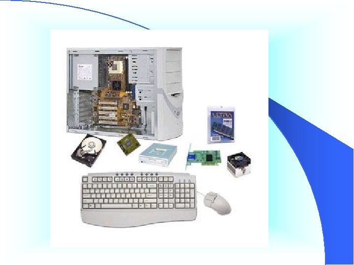
Hardware components
Hardware components l Processor l Input device l Output device l Memory unit l Computer case l Powersupply unit l Mother board
Processor
CPU § It is consists of arithmetic & logic units, control unit, memory unit § It is heart of computer.
Processor n The CPU – The chip or chips that interpret and execute program instructions and manage the functions of input, output, and storage devices.
PROCESSOR CHIP v
PROCESSOR CHIP
Input device
INPUT DEVICE l It is used to gave the commands and data to computer.
EXAMPLES l MOUSE l KEYBOARD l SCANNER l JOYSTIC l LIGHT PEN l TOUCH SCREEN l MIC. , etc
Mouse n An input device operated by rolling its ball across a flat surface. The mouse is used to control the on-screen pointer by pointing and clicking, double-clicking, or dragging objects on the screen.
Keyboard n Used to enter information into the computer and for giving commands.
Scanner n A device that allows pictures to be placed into a computer.
Touchpad n A pressure-sensitive and motion sensitive device used in place of a mouse.
Microphone n Allows the user to record sounds as input to their computer.
Output devices
OUTPUT DEVICES l It is used to display the processing results
EXAMPLES l Monitor l Printer l Speaker l Projector
Monitor n A display screen to provide “output” to the user. It is where you view the information your are working on.
Speakers l Used to generate or reproduce voice, music, and other sounds.
Printer n An output device that produces a hard copy on paper. It gives information to the user in printed form.
BUS
BUS l It is used to transfer the data and control l Types: – Unidirectional bus – Bi-directional bus
unidirectional bus l It transfer the data & control in single direction. l Symbol :
Bi-directional bus l It transfer the data & control in both direction. l Symbol :
MEMORY UNIT
Memory unit l It is used to store the data and program l All information are storing itself in digital signals
MEMORY UNIT l Types : – INTERNAL MEMORY – EXTERNAL MEMORY
INTERNAL MEMORY
INTERNAL MEMORY l ACTIVITY l TYPES OF MEMORY l MEMORY CAPACITY l BUS SPEED
Activity l It is consists of semiconductor device l It is used to store the program and data when processing time. l Low storage capacity l It is part of CPU.
TYPES OF MEMORY l RAM(Random Access Memory) l ROM(Random Only Memory)
ROM l It is used to store the information in permanently and read only. l It is not possible to write another information.
ROM l TYPES – PROM(PROGRAMMABLE ROM) – E-P-ROM(ERASABLE PROGRAMMABLE ROM) – E-E-P-ROM(ELECTRICALLY ERASABLE PROGRAMMABLE ROM)
RAM n Random Access Memory RAM is a computer’s temporary memory, which exists as chips on the motherboard near the CPU.
TYPES OF RAM l EDO RAM – Extended Data Out RAM l SD RAM – Synchronous Dynamic RAM l DDR RAM – Double Data Rate RAM l DDR-2 RAM – Double Data Rate – 2 RAM l RD RAM – Rambus Dynamic RAM
EDO RAM l Legs: – 72 nos l Cuttings: – 1 l Generation: – p 1 l Memory capacity: – 1 mb, 2 mb, 4 mb, 8 mb, 16 mb l Bus speed: – 16 mhz
SD RAM l Legs: – 168 nos l Cuttings: – 2 l generation; : – P 1, p 2 l Memory capacity: – 1 mb, 2 mb, 4 mb, 8 mb, 16 mb l Bus speed: – 16 mhz
DDR RAM l Legs: – 184 nos l Cuttings: – 1 l generation; : – P 4, l Memory capacity: – 128 mb, 256 mb, 512 mb, 1 gb, 2 gb l Bus speed: – PC 266, PC 300, PC 333, PC 400, PC 533
DDR-2 RAM l It simply DDR ram. l It is double transfer rate compare to DDR RAM l Memory capacity: – 512 mb, 1 gb, 2 gb l Bus speed: – PC 600, PC 800
RD RAM l Legs: – 228 nos l Cuttings: – nil l generation; : – P 4 l Memory capacity: – 1 mb, 2 mb, 4 mb, 8 mb, 16 mb l Bus speed: – 16 mhz
EXTERNAL MEMORY
EXTERNAL MEMORY l ACTIVITY l TYPES OF MEMORY l HARD DISK – CONSTRUCTION – STROGE METHOD – CAPACITY
ACTIVITY l It is consists of magnetic devices. l It is stores the information permanently. l It is a external device. l High memory capacity.
TYPES OF MEMORY l FLOPPY DISK DRIVE l COMPACT DISK DRIVE l DIGITAL VERSALITE DEVICE (DVD) l PENDRIVE l HARD DISK DIRVE
Floppy Disk Drive n A device that holds a removable floppy disk when in use; read/write heads read and write data to the diskette.
CD n Compact Disk – A type of optical storage device.
Hard Disk n Magnetic storage device in the computer.
HARD DISK CONSTRUCTION
CONSTRUCTION l It is magnetic storage device. l Hard disk consists – Read/write head – Spindle motor – Head actuator – Disk media(platter)
Hard Drive
Internal diagram Read/write head platter
How Data is Organized on Disk Tracks– circular areas of the disk – Length of a track one circumference of disk – Over 1000 on a hard disk – Data first written to outer most track l Sectors– Divides tracks sections – On a floppy 9 sectors exits l Cylinders– Logical groupings of the same track on each disk surface in a disk unit l Clusters– Groups of sectors used by operating system – 64 sectors in one cluster l
Tracks and sectors Can store 512 bytes Sector = small arc of track Track= concentric circle
CAPACITY= (N cylinder ) X( N track) X (N sector) X (512 bytes)
HARD DISK ALERT l Doesnot move or copy the folder to one place to another place l Save the folder to include display the another letter l Example: – Sai ---->folder name – ~$sai----> folder name
Hard disk alert l Bearing fault:
Hard disk alert l Read/head fault:
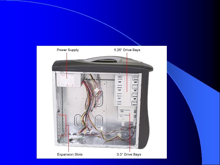
Computer Case n Contains the major components of the computer. It helps protect them.
Front of the Computer Case
Inside the Computer Case
Power supply unit
Power supply unit It includes power cord, switch, and cooling fan. Supplies power at appropriate voltages to the motherboard and internal disk drives. l It also converts alternating current to direct current and provides different voltages to different parts of the computer. l
Power Supply unit l SMPS(Switched mode Power Supply) – It used to computer system.
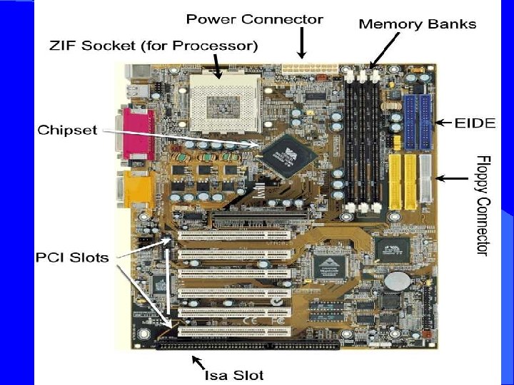
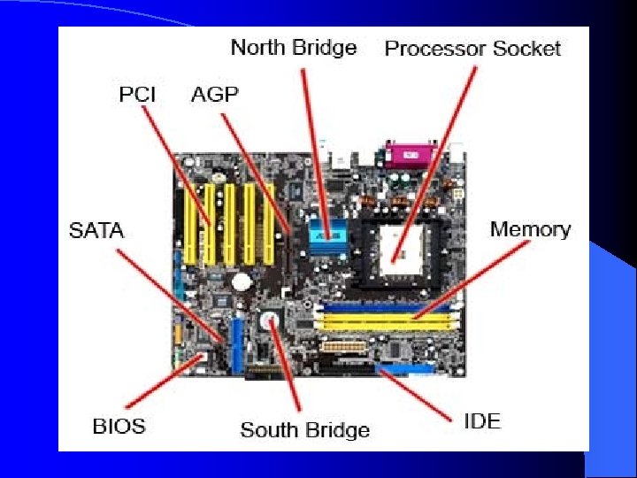
Mother board
Mother board l It is a body of computer. l It is includes – Processor – Chipset – Ports – I/O Slots – Connectors
Cards
Cards l It is a circuit board. l It contains many semiconductor device.
Cards l Types: – VGA CARD – SOUND CARD – LAN CARD – TUNER CARD – I/O CARD – AGP CARD
Video Card l Connects the computer to the monitor. It is a circuit board attached to the motherboard that contains the memory and other circuitry necessary to send information to the monitor for display on screen.
Sound Card l Connects the speakers and microphone to the computer.
Lan card l It is also called – Ethernet card – Nic card – Network adaptor l It used for – Network purpose
Network Card l A circuit board that connects the computer to the rest of the network usually using special cables.
Modem l The place where the computer is connected to the phone line.
Tuner card l It is used for – Cable tv purpose
I/O CARD l It is also called “add-on card” l It is used for – Serial port – Parallel port – FDC connector – IDC connector – Game port
AGP CARD l It used for graphics purpose
I/O SLOTS
I/O SLOTS l It is used to insert the card. l It is connect the process.
I/O SLOTS l TYPES: – ISA SLOT l Industrial Standard Archistructure – PCI SLOT l Peripheral Component Interconnect
ISA SLOT
ISA SLOT l It has 8 bit, 16 bit transmission – Black color l Insert cards – VGA CARD – SOUND CARD – INTERNAL MODEM – LAN CARD – ADD-ON CARD
ISA SLOT
PCI SLOT
PCI SLOT l It has 8 bit, 16 bit transmission – White or yellow color l Insert cards – VGA CARD – SOUND CARD – INTERNAL MODEM – LAN CARD – TUNER CARD
Ports
Ports
Ports l Types – Serial port – Parallel port – Game port – Special port
Serial port
Serial port l It has 9 pins. – Serial data transmission.
Serial port l Connecting devices: – Serial mouse – Serial printer – Scanner – External modem – Web camera – For Network
Parallel port
Parallel port l It has 25 pins. – Parallel data transmission
Parallel port l Connecting devices: – Parallel mouse – Parallel printer – Scanner – External modem – For network
Game port
Game port l It used to playing games in computer. l It has 15 pins – 1 st line ---> 7 pins – 2 nd line ---> 8 pins
SPECIAL PORT
Special port l It is used to connect external device(upto 175 device). l Example: – USB l UNIVERSAL SERIAL BUS – PEN DRIVE
connector
connector
Connector l Types: – FP CONNECTOR l FRONT PANEL – IDE CONNECTOR l INTERGRATED DEVICE ELECTRONICS – FDC CONNECTOR l FLOPPY DISK CONTROLLER
FP CONNECTOR l It connects – Restart button – Power switch
IDE CONNECTOR l It has 40 pins. l Connecting devices – HD DRIVE – CD DRIVE – ZIP DRIVE
FDC CONNECTOR l It has 34 pins. l Connecting devices: – FD A CONNECT – FD B CONNECT
Chipset
Chip set • It mediates communication between the CPU and the other components of the system, including main memory.
Chipset l It includes – South bridge – North bridge – Super I/O controller – Bios controller l It used to control the system configuration & booting – Sound controller l Controls sound output
South bridge
South bridge l It controls – PCI BUS – ISA BUS – USB PORT – IDE CONTROLLER – BIOS CONTROLLER – SOUND CONTROLLER – LAN CONTROLLER – SUPER I/O CONTROLLER
NORTH BRIDGE
North bridge l It controls – Processor – Memory(RAM) – AGP(Display)
SUPER I/O CONTROLLER
Super I/o controller l It controls – Key board – Mouse – Serial port – Parallel port – FDC – FPC
WORKING METHODLOGY
Input device Control system Memory Unit Output device CPU DATA PATH CONTROL PATH
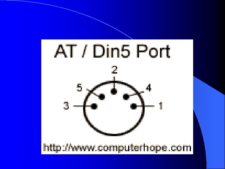
PS/2 PORT l KEY BOARD (AT/DIN 5) l MOUSE (PS/2)
AT / DIN 5 OVERVIEW o The Din 5 port, also known as the AT port, is generally found on older computers. o This port is commonly used for a computer keyboard.
Pin Description 1 Keyboard Clock 2 4 Keyboard Data Not Connected or Keyboard Reset Ground 5 Power +5 V 3
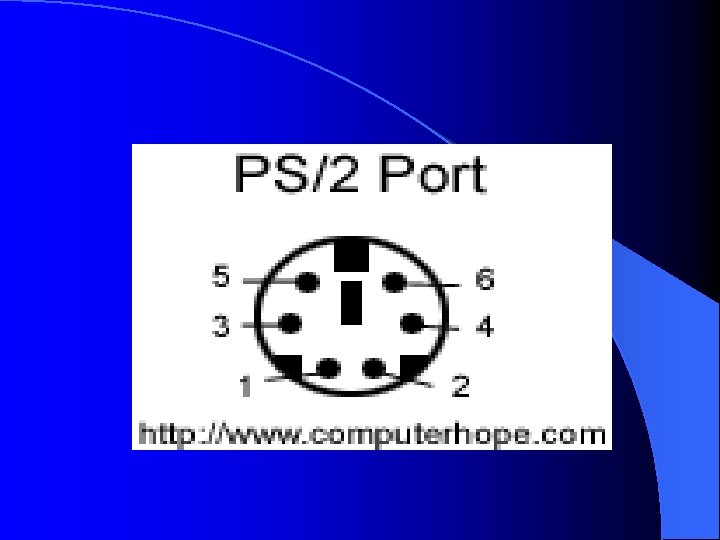
PS/2 PORT OVERVIEW l PS/2 ports are found on the majority of all IBM computers today. l This port is used to accept input devices such as the Mouse and Keyboard
Pin Description 1 Mouse Data 2 Not Connected 3 Ground 4 Power +5 V 5 Mouse Clock 6 Not Connected
C: D: Primary dos partition E: Extended dos partition F: G: Logical dos partition
TROUBLE SHOOTING l It is gave to solution for how to release computer hard ware troubles
TROUBLE SHOOTING l TROUBLES: – SYSTEM DEAD – CONTIONUOS RESTART – MEDIA NOT FOUND – PS/2 ERROR – VIRUS
SYSTEM DEAD
SYSTEM DEAD l CHECK FOLLOWING: l LED ON BUT SYSTEM DEAD – CPU WIRE MELTING – SMPS FAULT – ATX CABLE CONNECTION
SYSTEM DEAD l CHECK FOLLOWING: l LED OFF BUT SYSTEM DEAD – CMOS BATTERY LOW/DRY – BIOS IC FAULT – RAM DEAD – PROCESSOR FAULT
CONTIONUOS RESTART
CONTIONUOS RESTART l CHECK FOLLOWING: l WHEN POST BEFORE: – OS PROBLEM – CMOS BATTERY LOW/DRY – SOUTH BRIDGE FALULT – PROCESSOR HEAT – IDE CABLE CONNECTION
CONTIONUOS RESTART l CHECK FOLLOWING: l WHEN POST AFTER: – OS PROBLEM – FILE MISSING – VIRUS – HARD DISK RETRIVE PROBLEM – PROCESSOR HEAT
MEDIA NOT FOUND
MEDIA NOT FOUND l CHECK FOLLOWING: – HARD DISK PROBLEM – IDE CABLE CONNECTION – HARD DISK POWER SUPPLY – HARD DISK JUMPER – BIOS SETTING
PS/2 ERROR
PS/2 ERROR l CHECK FOLLOWING: – KEYBOARD SHORT CIRCUIT – MOUSE SHORT CIRCUIT
VIRUS
VIRUS
ANTI VIRUS
CONTROL PANEL