Computer Hardware Dr I Arul Rayappan Associate Professor
,")


 SCSI Small Computer System Interface Normally used in Servers. IDE")


 Now that you know what’s inside your hard disk and")


 Rectifier Filter Rectifier Inverter Filter 220 v AC 220")
 PS/2 (Small Din connector)")


 { outportb(0 x")


 and Software (developed in")
 is a single computer chip")


 Definition Asymmetric digital subscriber line (ADSL) is a new")
 Wire Gauge (AWG) Distance Wire Size (ft) (mm) Distance (km) 1.")


- Slides: 83
Computer Hardware Dr. I. Arul Rayappan Associate Professor of Physics, St. Joseph’s College (Autonomous), Tiruchirappalli-620 002.
The birth of Personal Computer Microcomputer with OS CP/M and upto 64 dump Terminals Personal computer PC By IBM Why not a system for single user like microcomputer at the cost of Home computer ? ? ? Home computer HC TV as monitor & Tape recorder as storage device
For this PC the IBM needs • A 8 bit processor which can support above 256 KB Memory • Single user OS which can work with Floppy Disk
Intel The Microprocessor Company released 8086 a 16 bit Processor with 1 MB memory support. …. failure in the market 8086 was modified into 8 bit processor as 8088 used by IBM for PC
Microsoft A small company of those days developed a OS as Disk Operating System DOS for IBM …later renamed as MSDOS
The First IBM PC configuration Processor 8088 - 4. 77 Mhz 256 KB RAM (640 kb) 2 x 360 KB Floppy disk drive 2 Parallel port 2 Serial port Mono Graphics display card Mono chromatic monitor 84 keys keyboard Operating system DOS (8 bit)
Microprocessor and PC Development Intel 8080 - 8 bit SIMM 30 pins 16 MB RAM VGA, ISA Slot IDE & ATA HDD Multi Media 8085 - 8 bit 8087 8086 -16 bit 8088 16/8 PC & PC XT 16 MB RAM (4 GB) Dual Speed CPU& RAM I/O 33 Mhz 80287 80387 80286 -16 bit With Coprocessor Cache mem 72 pin SIMM PCI Slot Tri speed CPU, Mem & I/O 80386 -32 bit PC 286 AT 12 -20 Mhz Windows 3. 1 Novel Net. Ware 80486 -32 bit PC 386 AT 33&40 Mhz Windows 95 80586
Cache Memory Address Bus CPU Data Bus Control lines Main Memory RAM
Microprocessor and PC Development Intel 8080 - 8 bit SIMM 30 pins 16 MB RAM VGA, ISA Slot IDE & ATA HDD Multi Media 8085 - 8 bit 8087 8086 -16 bit 8088 16/8 PC & PC XT AMD, Cyrix, Ti … 16 MB RAM (4 GB) Dual Speed CPU& RAM I/O 33 Mhz 80287 80387 80286 -16 bit 80386 -32 bit PC 286 AT 12 -20 Mhz Windows 3. 1 Novel Net. Ware With Coprocessor Cache mem 72 pin SIMM PCI Slot Tri speed CPU, Mem I/O 80486 -32 bit PC 386 AT 33&40 Mhz Windows 95 80586
80586 80686 Pentium-II Celeron Pentium-III 233 -533 Mhz 64 -256 KB Cache FSB 66 -133 Mhz SD RAM 168 pin Pentium-4 100 -166 Mhz, Internal Cache Integrated motherboard EDO RAM 233 -533 Mhz 512 KB Cache FSB 66 -133 Mhz SD RAM 168 pin 550 Mhz-1. 13 GHz 512 KB – 2 MBCache FSB 133 -333 Mhz SD RAM 168 pin
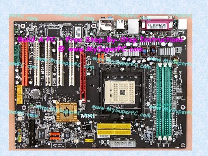
Personal Computer Architechture P O R T S Processor BUS controller M E M O R Y I/O Controller FDC HDC BIOS I/O Slots Motherboard RTC
Motherboard Normally a motherboard consists of CPU Socket & CPU Core voltage converter~1. 7 V Core Frequency generator e. g. 2. 8 Ghz Chip set Memory bus controller (FSB) I/O controllers RAM Slot & RAM Keyboard interface I/O Slots Integrated or All In One Motherboard Floppy Disk Controller Hard Disk Controller parallel ATA (PATA) Serial ATA (SATA) Parallel port, Serial port, USB ports Ethernet AGP display controller Sound Controller
Pentium-4 Some Important points in selecting the Processor Speed: 1 Ghz – 3. 4 Ghz …. FSB : 333 Mhz – 833 Mhz Three Level Cache: 256 Kb-4 Gb Models: Single core HT Dual Core
Advance Micro Devices AMD K 5 = 80586 Pentium K 6 = 80686 Pentium - II Athlon Sempron = Celeron = Pentium - III Pentium - 4
Today’s Computer Configuration Pentium-4 3. 0 Ghz Dual 2 Mb Cache 833 FSB AMD Athlon 4800+ Chipset Motherboard Intel Motherboard 102 FSB 533 Mhz 512 MB DDR 2 As same as other side 160 GB HDD SATA DVD drive Serial & Parallel ports USB port Monitor CRT or TFT Keyboard & mouse
Motherboard Intel CPU Intel Motherboard Intel Chipset Motherboard AMD CPU Third party Motherboard Chipset and Board Chipset by Other chipset both Intel itself Chipset by Intel Board Other companies manufacturers Like Mercury, Asus… Like VIA, SIS … Board by Other Companies Like Mercury, Asus Motherboard With higher FSB, AGP Slot, SATA interface and at least three PCI I/O Slots
Chipset There are two major sections in motherboard namely • Memory Section • I/O Section Memory decoders Bus controller FSB manager Etc For these things One SMD Chipset I/O Section I/O Decoder DMA & PIC PCI I/O slot manager Power manager AGP onboard & AGP Slot Etc One SMD
Memory RAM SIMM 30 pin 286 & 386 AT SIMM 72 pin 486 & Pentium K 5 from AMD EDO RAM (Enhance Data Out) Pentium, Pentium-II & III Athalon SD RAM (Synchronous Data) Pentium – 4 RD RAM (Ram Data bus) DDR Pentium – 4 Single core & HT FSB: 400 Mhz (Double Data Rate) Pentium – 4 Dual core FSB: 533 Mhz DDR 2
Hard Disk Drive (HDD) SCSI Small Computer System Interface Normally used in Servers. IDE (ATA) Integrated Drive Electronics Advance Technology Attachment PATA Parallel ATA Serial ATA (7200 RPM & Ultra DMA 133 Mhz)
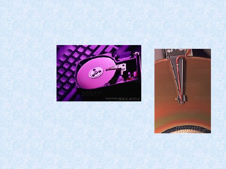
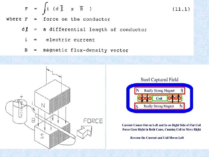
Voice Coil Actuator A Voice Coil Actuator is a very simple positioning device that utilizes a coil of wire in a permanent magnetic field. In speakers, the magnet is cylindrical North-South Pole in-out (or top-bottom of the cylinder) and the coil goes North-to-South Pole (or top-bottom of an inner cylinder). Changing the amplitude and polarity of the current in the coil causes an in-out force that 'plays' the diaphragm on the speaker. The spring tension on the diaphragm keeps the voice coil actuator centered when no current is applied. You know the voice coil and speaker. . . here's Alexander Graham Bell's original invention drawing from 1876 (courtesy U. S. Library of Congress):
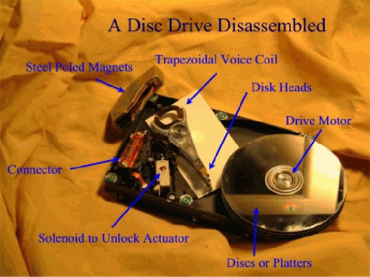
The hard disk voice coil actuator is used to position disk heads across the platter of the disk. It is a 'voice coil actuator' in that it only uses a coil and a permanent magnet in a simple push-pull fashion, but doesn't work like a speaker voice coil actuator. The geometries are completely different. The voice coil actuator looks like this:
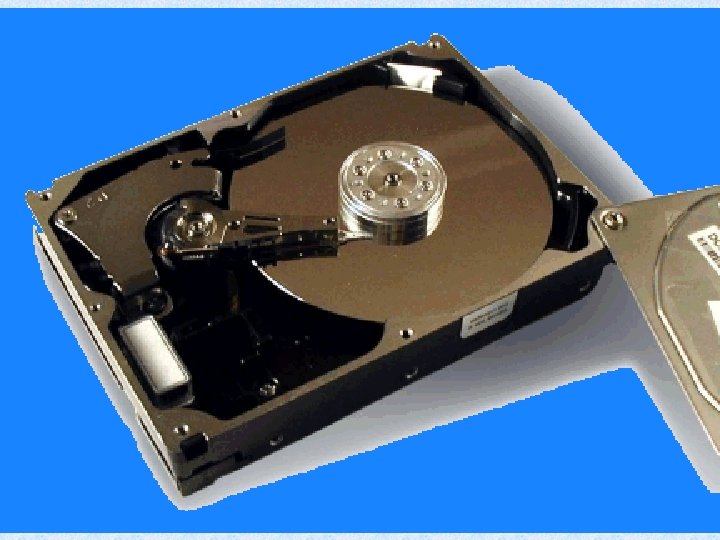
Hard Disk Basics Hard disks are organized as a concentric stack of platters. The data is stored on concentric circles on the surfaces known as tracks. Sections within each track are called sectors. A sector is the smallest physical storage unit on a disk and typically it will hold 512 bytes of data.
Zoned Bit Recording (ZBR) Now that you know what’s inside your hard disk and how the data is stored, it’s time to add some complexity. If you imagine the surface of a disk platter, considering a constant number of sectors per track and knowing that track lengths increase the farther a track resides from the center of the disk (they are concentric circles), it’s not hard to conclude that the outer data sectors are longer than the inner data sectors. This means that the outer tracks are greatly underutilized, because in theory they can hold many more sectors given the same linear bit density. In order to increase capacity and eliminate this wasted space, a technique called zone bit recording (ZBR) is employed on modern hard disks. With this technique, tracks are grouped into zones based on their distance from the center of the disk, and each zone is assigned a number of sectors per track. As you move from the innermost part of the disk to the outer edge, you move through different zones, each containing more sectors per track than the one before. This allows for more efficient use of the larger tracks on the outside of the disk.
Input output Ports in Computer To communicate with other devices and for interfacing there some ports in computer Parallel port for printer and 8 bit interfacing Serial port for mouse, modem and serial interfacing USB ports Ether net VGA Universal Serial Bus port for serial communication with devices at closer distances Speed 12 Mbps & 127 devices for LAN Monitor
Power Supply 220 v Ac 20/9 V AC Transformer Rectifier Filter 1 computer 1 h r = 100 W 1 computer 10 hrs = 1000 W 100 computer 10 hrs = 10000 W 10 colleges like this = 100000 W 100 Cites/towns = 10000000 W=10 MW 20 States = 200 MW Taking TV into account = 2000 MW 12/5 V DC 8/20 A Output 20/9 V DC 8/20 A Regulator 180 W 100 W ? ~100 w
Switching Mode Power Supply (SMPS) Rectifier Filter Rectifier Inverter Filter 220 v AC 220 v DC AC to DC 12/5 V AC 12/5 V DC DC to AC Feed back & Correction
Keyboard & Mouse Keyboard Interface Mouse Interface AT (Din connector) PS/2 (Small Din connector) Serial (9 Pin D type Connector) PS/2 (Small Din connector)
Monitor n Display Card PCI /AGP I/o Card or On board (15 Pin D type Connector) n Monitor CRT TFT(LCD)
Interfacing Techniques
Parallel Port Anatomy: Following are the pin outs: • 8 Output pins [D 0 to D 7] • 5 Status pins [S 4 to S 7 and S 3] • 4 Control pins [C 0 to C 3] • 8 ground pins [18 to 25] The Pins having a bar over them , means that the signal is inverted by the parallel port's hardware. if a 1 were to appear on the 11 pin [S 7], the PC would see a 0. The Status pins are mainly used by the PC to know the status of the printer , like if there is paper in the printer, end of paper etc.
Data Port In this address the CPU writes the data to be sent to the printer. It is an OUTPUT port. The eight data bits (D 0 -D 7) are latched to appear in the output connector. Data Bits Table BIT FUNCTION D 0 data 0 D 1 data 1 D 2 data 2 D 3 data 3 D 4 data 4 D 5 data 5 D 6 data 6 D 7 data 7 PIN 2 3 4 5 6 7 8 9
Status Port This is an INPUT port. These signals are used by the CPU to know the state of the printer. Status Bits Table BIT FUNCTION PIN D 0 not used D 1 not used D 2 not used D 3 ERROR/ 15 D 4 SLCT/ 17 D 5 PE 12 D 6 ACK/ 10 D 7 BUSY/ 11
Control Port Control Bits Table In this port the computer writes the signals that control the printer. Therefore, it is an OUTPUT port, BIT FUNCTION PIN D 0 D 1 D 2 D 3 STROBE AUTO FD INIT/ SLCT IN/ 1 14 16 17 D 4 D 5 D 6 IRQ 7 not used D 7 not used
The computer has three LPTn ports. The addresses of the Data, Status and Control signals for each LPTn port are listed below. Each port works in the same way that LPT 1 does. Addresses of LPTn PORT DATA STATUS CONTROL LPT 1 378 H 379 H 37 AH LPT 2 278 H 279 H 27 AH LPT 3 3 BCH 2 BDH 3 BEH
LED flash #include <studio. h> #include <dos. h> void main(void) { outportb(0 x 378, 0 x. FF) ; outportb(0 x 378, 0 x 00) Stepper Motor control } #include<studio. h> #include<conio. h> #include<dos. h> main() { outportb(0 x 378, 0 x 01); outportb(0 x 378, 0 x 02); outportb(0 x 378, 0 x 04); outportb(0 x 378, 0 x 08) }
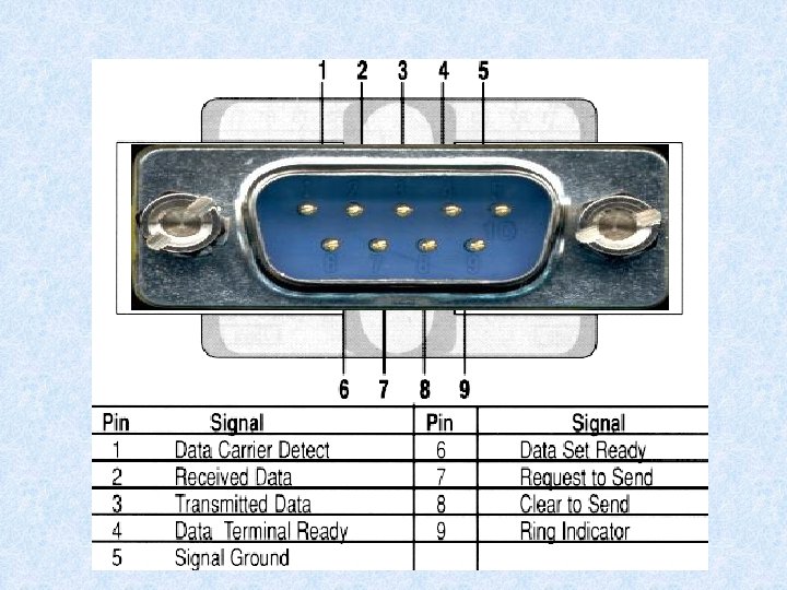
RS 232 Serial Port Electronic data communications between elements will generally fall into two broad categories: single-ended and differential. RS 232 (single-ended) was introduced in 1962, rumors for its early It is widely used through the industry. Independent channels are established for two-way (full-duplex) communications. The RS 232 signals are represented by voltage levels with respect to a system common (power / logic ground). The "idle" state (MARK) has the signal level negative with respect to common, and the "active" state (SPACE) has the signal level positive with respect to common. RS 232 has numerous handshaking lines (primarily used with modems), and also specifies a communications protocol.
The RS-232 interface presupposes a common ground between the DTE and DCE. RS 232 data is bi-polar. . +3 TO +12 volts indicates an "ON or 0 -state (SPACE) condition" while A -3 to -12 volts indicates an "OFF" 1 -state (MARK) condition. . Modern computer equipment ignores the negative level and accepts a zero voltage level as the "OFF" state. In fact, the "ON" state may be achieved with lesser positive potential. This means circuits powered by 5 VDC are capable of driving RS 232 circuits directly, however, the overall range that the RS 232 signal may be transmitted/received may be dramatically reduced.
Description Signal 9 -pin DTE 25 -pin DCE Carrier Detect CD 1 8 from Modem Receive Data RD 2 3 from Modem Transmit Data TD 3 2 from Terminal/Computer DTR 4 20 from Terminal/Computer Signal Ground SG 5 7 from Modem Data Set Ready DSR 6 6 from Modem Request to Send RTS 7 4 from Terminal/Computer Clear to Send CTS 8 5 from Modem Ring Indicator RI 9 Data Terminal Ready 22 Source DTE or DCE from Modem
Microcontrollers and Embedded Systems are a combination of Hardware (microcontrollers) and Software (developed in assembler, c, c++…) designed to perform a specific function An embedded product uses microcontrollers to do one task and one task only.
What is a Microcontroller? A microcontroller (often abbreviated MCU) is a single computer chip (integrated circuit) that executes a user program, normally for the purpose of controlling some device, hence the name microcontroller. The program is normally contained either in a second chip, called an EPROM, or within the same chip as the microcontroller itself. A microcontroller is normally found in devices such as microwave ovens, automobiles, keyboards, CD players, cell phones, VCRs, security systems, time & attendance clocks, etc.
Microprocessor Vs Microcontrollers are used in devices that require some amount of computing power but donot require as much computing power as that provided by a complex (and expensive) 486 or Pentium system which generally requires a large amount of supporting circuitry (large motherboards, hundreds of megabytes of RAM, hard drives, hard drive controllers, video cards, etc). A microwave oven just does not need that much computing power. Microcontroller-based systems are generally smaller, more reliable, and cheaper. They are ideal for the types of applications described above where cost and unit size are very important considerations. In such applications it is almost always desirable to produce circuits that require the smallest number of integrated circuits, that require the smallest amount of physical space, require the least amount of energy, and cost as little as possible.
Simple comparison: Pentium vs. 8051 FEATURE 8051 PENTIUM COMMENT Clock Speed 12 Mhz. typical but 60 MHz. ICs available 1, 000 MHz. (1 GHz. ) 8051 internally divides clock by 12 so for 12 MHz. clock effective clock rate is just 1 MHz. Address bus 16 bits 32 bits 8051 can address 216, or 64 Kbytes of memory. Pentium can address 232, or 4 Giga. Bytes of memory. Data bus 8 bits 64 bits Pentium’s wide bus allows very fast data transfers. ALU width 8 bits 32 bits But - Pentium has multiple 32 bit ALUs – along with floatingpoint units. Applications Domestic appliances, Peripherals, automotive etc. Personal Computers And other high performance
Ext int Microcontroller interrupt Timer 0 Timer 1 ROM RAM Bus control 4 I/o ports CPU OSC Serial port
Microcontroller Manufacturing Companies There are FOUR major companies manufacturing 8 bit controllers 1. Motorola (6811) 2. Intel (8051 MCS 51) 3. Zilog (Z 8) 4. PIC (16 X____) Microchip
8051 Microcontroller Overview Functional block of the internal operation of an 8051
Port Organization of MCS 51 Port 0 P 1. 0 – P 1. 7 P 0. 0 – P 0. 7 P 1 P 0 Port 3 Port 2 P 3. 0 – P 3. 7 P 2. 0 – P 2. 7 P 3 P 2
Port Assignments Port 0 : Input/Output Port & AD 0 -AD 7 for ext memory Port 1 : Input/Output Port 2 : Input/Output Port & A 8 -A 15 for ext Memory Port 3 : Input/Output Port P 3. 0 : Rx. D P 3. 1 : Tx. D P 3. 2 : INTO’ P 3. 3 : INT 1’ P 3. 4 : T 0 P 3. 5 : T 1 P 3. 6 : WR’ P 3. 7 : RD’
A Circuit using 89 c 51 40 +5 V Pin 40 +vcc 9 20 Gnd 89 c 51 31 18 19 20 GND 9 Reset 18 OSC 1 19 OSC 2 31 Ext Acces
Burglar alarm system hardware
Input circuit Output circuit
ALARM_1 Program flow chart
ALARM_1 Program source code ORG 0000 h ; define memory start address 000 ; Initialise the I/O ports MOV P 3, #0 ffh ; write all ones to P 3 to use as an input port MOV P 1, #00 ; all zeros to put P 1 in a known output state POLL: MOV A, P 3 ; read P 3 to accumulator CJNE A, #00 h, ALARM ; if not all zeros then jump to ALARM LJMP POLL ; else loop back to POLL ALARM: SETB P 1. 7 ; enable the BELL by setting P 1. 7 high END_LOOP: LJMP END_LOOP ; program just loops around here END ; end of program
Hardware circuit with timing diagram for sound
Source code for example program to sound 500 Hz ORG 0000 h MOV P 1, #00 LOOP: SETB P 1. 0 LCALL ONE_MILLI_SUB CLR P 1. 0 LCALL ONE_MILLI_SUB LJMP LOOP ONE_MILLI_SUB PUSH 07 h MOV R 7, #250 d LOOP_1_MILLI: NOP DJNZ R 7, LOOP_1_MILLI POP 07 h RET END ; start address is 0000 h ; clear all bits on P 1 ; set P 1. 0 high ; delay one millisecond ; set P 1. 0 low ; delay one millisecond ; loop around! ; save R 7 to stack ; 250 decimal to R 7 to count 250 loops ; loops 250 times ; inserted NOPs to cause delay ; decrement R 7, if not zero loop back ; restore R 7 to original value ; return from subroutine ; end of program
Serial Communication
Block diagram of UART transmitter
Block diagram of UART receiver
System Assembling 1. Collect all The materials 2. Test the SMPS for its various voltages +12 V, -12 V, +5 V, -5 V, 3. 3 V
Take the motherboard check for physical damages
Insert the CPU
Mount the cooling FAN
Power connection for FAN
Fix the RAM in its Slot
Power Connection for motherboard
Fix the Storage device like Floppy Disk Drive , Hard Disk Drive, CD/DVD drive and Connect Data cable and Power cable
Hard Disk Drive Connections
Connect the data cable in motherboard
Hard Disk Data cable to Motherboard
Trouble Shooting a System Troubles in the system can be put in two main Categories Before Boot Problem After Boot Problem Before Display Software & OS Based After display Virus Hardware Problems
Trouble Shooting a System Before boot and Display 1. A System Reports Nothing on the screen Check the power cable and switch On No response Check monitor Power LED OFF Check the Power cable the monitor ON Check the Panel controls Blinking Check the Data Cable the monitor Data cable OK Problem in the system May be the SMPS or the motherboard side To check SMPS – Watch your keyboard LEDS during Switch ON If Flashing once or twice on problem in SMPS other conformation is SMPS FAN
Trouble Shooting a System Before boot and Display Contd The problem may in the motherboard, CPU, Reset Switch Check the Reset Switch Check Hard Disk Data Cable 2. A System Reports Nothing on the screen But Long Beep RAM Or RAM Slot Problem.
After Display Problems The BIOS give proper information by its POST After Boot Problems The BIOS and OS give the information
Asymmetric Digital Subscriber Line (ADSL) Definition Asymmetric digital subscriber line (ADSL) is a new modem technology that converts existing twisted-pair telephone lines into access paths for high-speed communications of various sorts. Overview ADSL can transmit more than 6 Mbps to a subscriber—enough to provide Internet access, video-on-demand, and LAN access. In interactive mode it can transmit more than 640 kbps in both directions. This increases the existing access capacity by more than fifty-fold enabling the transformation of the existing public network. No longer is it limited to voice, text, and low-resolution graphics. It promises to be nothing less than an ubiquitous system that can provide multimedia (including full-motion video) to the entire country.
Data Rate (Mbps) Wire Gauge (AWG) Distance Wire Size (ft) (mm) Distance (km) 1. 5– 2. 0 24 18, 000 0. 5 5. 5 1. 5– 2. 0 26 15, 000 0. 4 4. 6 6. 1 24 12, 000 0. 5 3. 7 6. 1 26 9, 000 0. 4 2. 7
Be Informative…. Be A Hard worker…. Be A successful Person