Computer Graphics CC 416 Lecture 01 Introduction Dr


 Presentation Graphics Computer Art Entertainment")
")


 & Raster scan display")


 display • A matrix of diodes are arranged to form")
 • A polarized light is generated • The polarized light")


- Slides: 50
Computer Graphics CC 416 Lecture 01: Introduction Dr. Manal Helal – Fall 2014
1 -2 Course Description • Introduction - History and survey of graphics applications - Overview of graphics systems and output devices - Output primitives including points, lines, circles, splines, area filling, and character generation - Attributes of output primitives - Two dimensional transformations - Windowing and clipping - Interactive input methods – Three dimensional graphics.
1 -3 Course Topics • • • Introduction, history and Survey of Computer Graphics Applications Overview of Graphics Systems : Raster and Random scan displays Color diplay – Color models (RGB, CMY, . . ) Output Primitives : Bresenham line and Mid-point Circle / Ellipse drawing algorithms Drawing free curves : Bezier and Spline techniques Two – Dimensional Transformations Viewing transformation Line and Polygon clipping algorithms Filling algorithms Animation Three – Dimensional Concepts Viewing and Representation Three – Dimensional Transformations
1 -4 Grading Scheme • Week 7 • • Quizzes Lab Submissions Assignments Midterm 1 5% 20% • Week 12 • • • Quizzes Lab Submissions Assignments Midterm 2 Project • Final Exam 5% 2. 5% 10% 40%
1 -5 Course Rules • • Website: – http: //moodle. manalhelal. com/course/view. php? id=6 – Signup using First and Last Names exactly as your records in AASTMT, and your student ID as your student ID in AASTMT. Otherwise, your grades will not be transferred to your academy records. – Login often to follow up with assignment deadlines and announcements. Its your responsibility to keep up with the course. Failure to receive emails or notifications is no excuse. Everything is announced in class and then published in moodle. Academic Honesty: – Please confirm with the AASTMT policies regarding plagiarism and cheating. A zero grade for the violating submission will be given the first time, then reported to the department for further action. – Please ask questions in the online forum to allow everyone to join and benefit from the discussions, and avoid private emails to the lecturers and TAs. Contact the teachers privately only about your personal grades or circumstances, not about the course content.
1 -6 How to score A+ in this course? Please do all practicals and assignments and study regularly. In case of problems, please ask questions. Accumulating problems will make things worse as the semester goes by.
Office Hours • Dr. Manal Helal – Room 308 – Sun and Monday 2: 00 -04: 00 p. m. or by appointment • Eng. Nour – to be announced • Eng. Hossam – to be announced Fall 2014 CC 215 Data Structures 7
Computer Graphics Applications • • Computer Aided Design (CAD) Presentation Graphics Computer Art Entertainment Education and Training Visualization Image Processing Graphical User Interface
Computer Aided Design (CAD)
Presentation Graphics Architectural presentation
Visualization Protein Structure aerodynamics flow
Computer Art Fractals
Entertainment
Education and Training
Image Processing Feature detection Enhancement
Graphical User Interface
Graphics Systems • • • Video Display Devices Raster- Scan Systems Random Scan Systems Input Devices Hard Copy Devices Graphics Software
Video Display Devices – Cathode Ray Tube (CRT) & Raster scan display
Raster Scan Display
Flat panel Display • Plasma panels – The cells are sandwiched between x- and y-axis panel – Each pixel is made up of three cells full of ionized gas – When charged, the gas emits ultraviolet light that causes the phosphors to emit their color – The amount of charge determines the intensity
Light Emitting Diode (LED) display • A matrix of diodes are arranged to form the pixel position in the display • Image definition is stored in a buffer
Liquid Crystal Display (LCD) • A polarized light is generated • The polarized light is passed through a liquid crystal material • The liquid crystal material can be aligned to block or bypass the light
3 Dimensional Viewing Devices • 3 D devices reflect a CRT image from a vibrating flexible mirror. • The vibration changes the focal length such that each point is reflected from the mirror into a spatial position corresponding to the distance of the point from a specified viewing location.
Virtual Reality
Video Controller – Frame buffer is a part of memory for graphics and has the intensity value for all the screen coordinates. – According to the photo info an application program updates frame buffer. – Then, the display controller converts the binary values to pixel information which is later displayed in to a Cathode Ray Tube. – Frame buffer can be used as a part of computer memory using a common bus or it can be used separately by using host system bus and graphics system bus.
Coordinating system – There are 3 defined coordinate systems: 1. World Coordinate System 2. Normalized Device Coordinate 3. Device Coordinate System
• World Coordinate System: – It is a write-hand coordinate system – It allows the user to set any conversion dimension regardless of any output device. • Normalized Device Coordinate: – Before final conversion to device specific coordinates we convert our graphics primitives to normalized device coordinates. – It makes graphics system visible enough to match with any output graphical devices. – Normalized Coordinate of X and Y (point coordinate) are each assigned values to the interval from 0 to 1.
Device Coordinate System : – The normalized coordinates are transformed into device – coordinates within the range from (0, 0) to (Xmax , Ymax), where this is the coordinates of specific device.
Screen Coordinates
Using Color in Computer Graphics • Aesthetic uses • Highlight • Code numeric quantities – Scientific visualization: fluids in computational fluid dynamics (streamlines) – Color legends
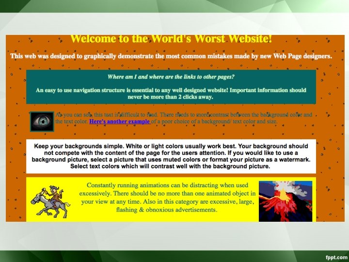
• Color Selection – Visually appealing. – Convey a message. • Careless use of color is dangerous – in experiments, poor color choices reduced user performance by one-third – “Worst Website”: • http: //www. angelfire. com/super/badwebs/main. htm
Color Models • What is the color? – Color is a sensation produced by the human eye and nervous system. • Photosensitive Receptors – Rods: 130, 000 night vision + peripheral (scotopic) – Cones: 5 -7, 000, daylight vision + acuity (one point only) » L-cones » M-cones » S-cones
From left to right, the curves above show the sensitivity of the S, M, and L cones to various wavelengths of visible light
• It is useful to represent a color by a set of exactly three numbers. - In practice, the set of three numbers must be related to some actual color reproduction process. The numbers commonly specify portions of some set of primary colors such as:
• A color model is an orderly system for creating a whole range of colors from a small Mixing of 3 primaries set of primary colors. Target colour overlap Adjust intensities to match the colour
Types of Color model – There are two types of color models, those that are subtractive and those that are additive. – Additive color models use light to display color while subtractive models use printing inks. – Colors perceived in additive models are the result of transmitted light. – Colors perceived in subtractive models are the result of reflected light.
Color Models for Raster Graphics • Hardware-oriented models: do not relate to concepts of hue, saturation, brightness – – – RGB, used with color CRT monitors YIQ, broadcast TV color system CMY (cyan, magenta, yellow) color printing CMYK (cyan, magenta, yellow, black) color printing IRODORI, six-primary-color projection system • User-oriented models – HSV (hue, saturation, value), corresponds to the way that the human describe and interpret color. – HLS (hue, lightness, saturation) – The Munsell system – CIE Lab
Problems
Solution
The CIE 1931 Standard Observer represents the color perception of a "normal" person. The curves show the intensity of X, Y, and Z values (akin to cone response) for a given wavelength
RGB Color Model • • • Additive color model. For computer displays. Uses light to display color. Colors result from transmitted light. Red + Green + Blue = White.
– The individual contributions of each primary are added together to yield the result. The RGB cube (Grays on dotted main diagonal) Main diagonal => gray levels • black is (0, 0, 0) • white is (1, 1, 1)
• The color gamut covered by the RGB model is defined by the chromaticities of a CRT’s phosphors. • Two CRTs with different phosphors will cover different gamuts. – Conversion between colors specified in the gamut of one CRT to the gamut of another CRT. • Convert one to XYZ, then convert from XYZ to another
• Each transformation – Xr, Xg and Xb are the weights applied to the monitors’ RGB colors to find X and so on. • With M 1 and M 2 the matrices that convert from each of the two monitor’s gamuts to CIE, M 2 -1 M 1 converts from the RGB of monitor 1 to the RGB of monitor 2. éX ù éX r ê ú=ê ê Y ú ê Yr êë Z úû êë Z r Xg Yg Zg Xb ù éRù úê ú Yb ú êG ú Z b úû êë B úû
CMY Color Model • CMY stands for Cyan, Magenta, and Yellow, which are the complements of red, green and blue • Subtractive color model: Used as filters to subtract color from white light. • For printed material. • Uses ink to display color. • Colors result from reflected light: • Cyan + Magenta + Yellow = Black. Colors are specified by what is removed or subtracted from white light, rather than by what is added to blackness.
• Relations between RGB and CMY Green é C ù é 1ù é R ù ê ú ê ú = ê M ú ê 1ú ê G ú êë Y úû êë 1úû êë B úû (minus red) Cyan Yellow Black Blue (minus blue) Red Magenta (minus green) • The unit column vector is the RGB representation for white and the CMY representation for black.
• A knowledge of CMY is important when dealing with hardcopy devices that deposit colored pigments onto paper: electrostatic and ink-jet plotters. – When a surface is coated with cyan ink, no red light is reflected from the surface. – Cyan subtracts red from the reflected white light. – Cyan is white minus red, that is blue plus green. – Magenta absorbs green, so it is red plus blue. – Etc. dye color absorbs reflects cyan red blue and magenta green blue and red yellow blue red and green black all none
Use RGB For Screen Displays and CMYK For Print - It is important to choose the right color model for the job. If your images will be printed, then convert them to CMYK and manually bring them into gamut before printing. If your images are to be displayed on a computer, then make sure you use RGB color so the full gamut will be available for display. Because both models can be available at the same time while using an application, it is easy to make a mistake and choose the wrong palette or set of color swatches.
CMYK Color Model: • Most devices that deposit colored pigments on paper such as color printer require CMY data input. • Equal amounts of cyan, magenta, yellow will produce black. • But in practice we use black as a dominant color for printing so we add the black color to the model CMYK