COMPUTER AIDED ENGINEERING DRAWING Why Engineering Drawings Engineering


- Slides: 69
COMPUTER AIDED ENGINEERING DRAWING
Why Engineering Drawings? • • Engineering drawing is a formal and precise way of communicating information about the shape, size, features and precision of physical objects. • • Drawing is the universal language of engineering.
Line Conventions • • • Visible Lines – solid thick lines that represent visible edges or contours Hidden Lines – short evenly spaced dashes that depict hidden features Section Lines – solid thin lines that indicate cut surfaces Center Lines – alternating long and short dashes Dimensioning – Dimension Lines - solid thin lines showing dimension extent/direction – Extension Lines - solid thin lines showing point or line to which dimension applies – Leaders – direct notes, dimensions, symbols, part numbers, etc. to features on drawing • • Cutting-Plane and Viewing-Plane Lines – indicate location of cutting planes for sectional views and the viewing position for removed partial views Break Lines – indicate only portion of object is drawn. May be random “squiggled” line or thin dashes joined by zigzags. Phantom Lines – long thin dashes separated by pairs of short dashes indicate alternate positions of moving parts, adjacent position of related parts and repeated detail Chain Line – Lines or surfaces with special requirements
Viewing-plane line 1 2 Extension line 3 Dimension Line 4 Center Line 5 Hidden Line 6 Break Line 7 Cutting-plane Line 8 Visible Line 9 Center Line (of motion) 10 Leader Phantom Line 14 13 Section Line 12 SECTION A-A 11 VIEW B-B Source: http: //www. genium. com/pdf/dmpc. pdf
Sketching • Drawings made without mechanical drawing tools – Free-Hand
Projection of points • In 1 st quadrant • In 2 nd quadrant • In 3 rd quadrant • In 4 th quadrant
Quadrants
Projection of points In 1 st quadrant • Above HP • In front of VP A point is 30 mm in front of VP, 40 mm above HP and 25 mm in front of left profile plane. Draw its projections.
Projection of Points • In 1 st quadrant • In 2 nd quadrant • In 3 rd quadrant • In 4 th quadrant
Projection of point – I quadrant
Projection of point – I quadrant
Projection of points In 1 st quadrant • Above HP • In front of VP A point is 30 mm in front of VP, 25 mm above HP. Draw its projections.
Projection of points In 1 st quadrant 2. Draw the projection of a point P that is 30 mm in front of VP, 50 mm above HP and 35 mm in front of right profile plane
Solution
Projection of point – II quadrant
Projection of point – II quadrant
Projection of point – II quadrant • Draw the projection of a point A lying 60 mm above HP and 40 mm behind VP
Projection of point – II quadrant • A point is 20 mm above HP, 45 mm behind VP and 25 mm in front of RPP. Draw its projections.
Solution
Projection of point – III quadrant
Projection of point – III quadrant
Projection of point – III quadrant • A point P is 30 mm below HP, 20 mm behind VP and 25 mm behind RPP. Draw the projections of the point.
Projection of point – III quadrant • Problem 2. • Draw the projection of a point P that is lying in HP, 20 mm behind VP and 30 mm behind RPP
Solution
Projection of point – IV quadrant
Projection of point – IV quadrant
Projection of point – IV quadrant • A point P is lying 50 mm below HP and 40 mm in front of VP. Draw its projection.
Projection of point – IV quadrant • Problem 2 • Draw the top, front and profile view of a point A 40 mm in front of VP, 30 mm below HP and 25 mm in front of LPP
Solution
Projection of Lines • Straight line: Defined as the locus of a point, which moves linearly. • Or – Shortest distance between any two given points. • Straight line is one dimensional object. • Projection of Line: is obtained by placing the straight line in space and projecting the end points of the line on the principal planes of projection (HP, VP, PP) and connecting the points. • From now on we look at the projections with respect to First quadrant only.
Projection of Lines • A line may be held in space with reference to HP, VP and PP in infinite number of positions. 1. 2. 3. 4. Parallel to both the planes Parallel to one plane and perpendicular to the other Parallel to one plane and inclined to the other Inclined to both the planes
Parallel to both the planes
Parallel to one plane and perpendicular to the other
Parallel to one plane and inclined to the other
Inclined to both the planes
True length • If a line is parallel to any one of the planes, its projection on that plane will give true length
True length and true inclination • If a line is inclined to one principal plane and is parallel to the other plane, its projection on that plane gives true length and true inclination.
• If a line is parallel to VP and inclined at θ to HP, the front view will be true length and at true inclination θ
• If a line is parallel to HP and inclined at ø to VP, the top view will be true length and true inclination ø.
• θ is the inclination always measured with respect to object and HP • ø is the inclination always measured with respect to object and VP
Parallel to both the planes
Problem 1 • Draw the projections of a line 70 mm long when it is parallel to both HP and VP. The line is 20 mm from both HP and VP.
Solution :
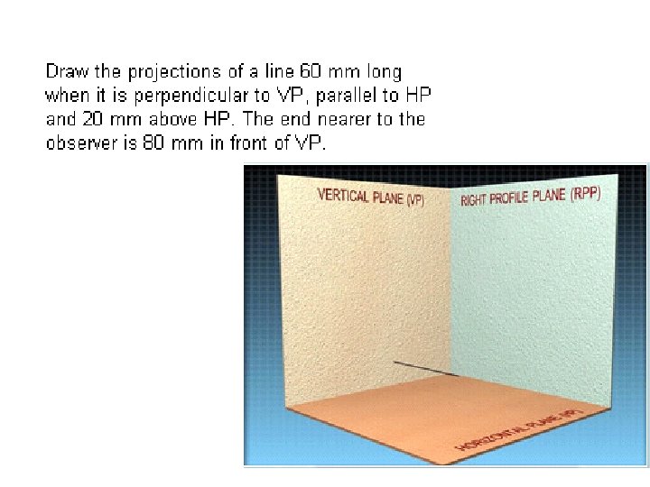
Parallel to one plane and perpendicular to the other
• Problem :
Solution :
Solution :
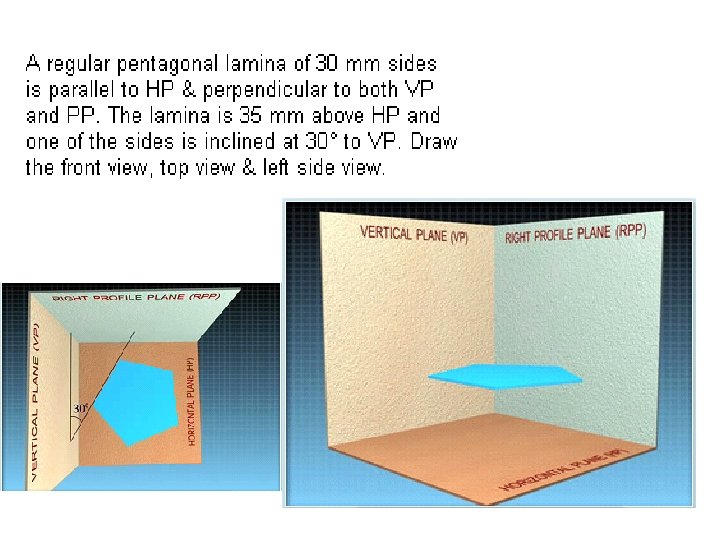
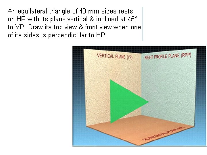
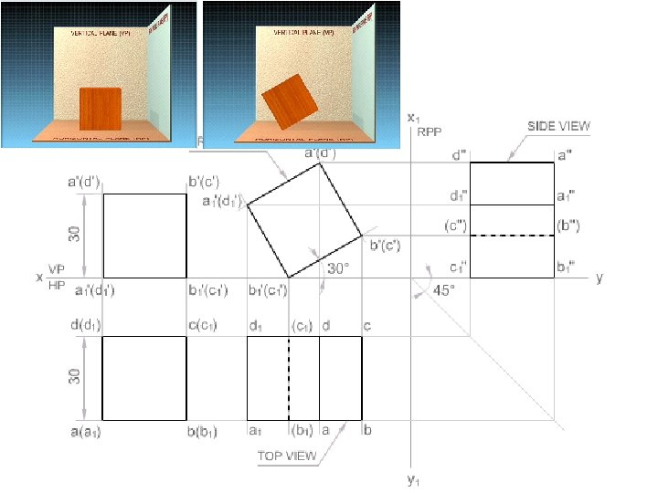
Projection of Planes
Solution
Solution
Solution
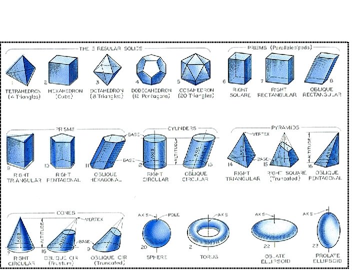
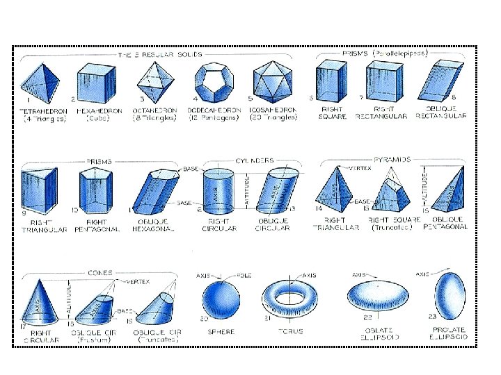
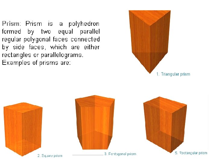
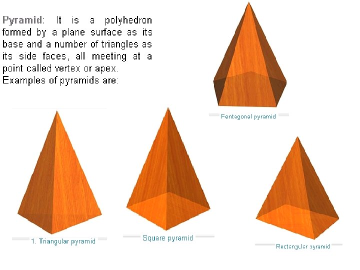
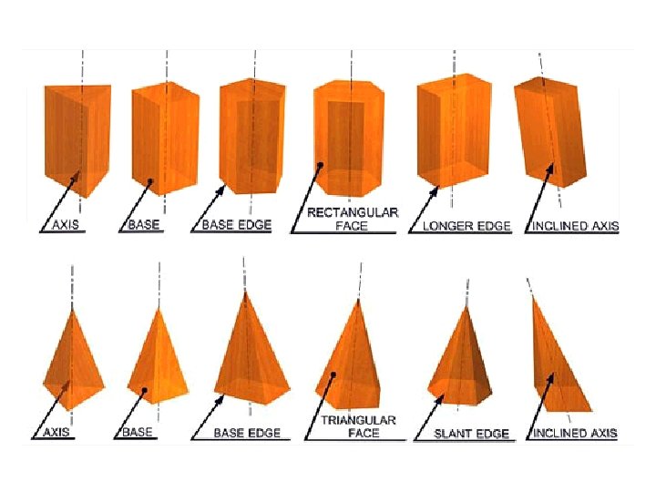
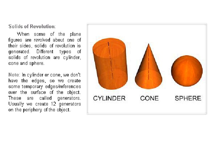
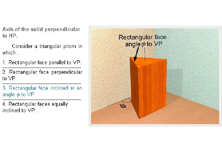
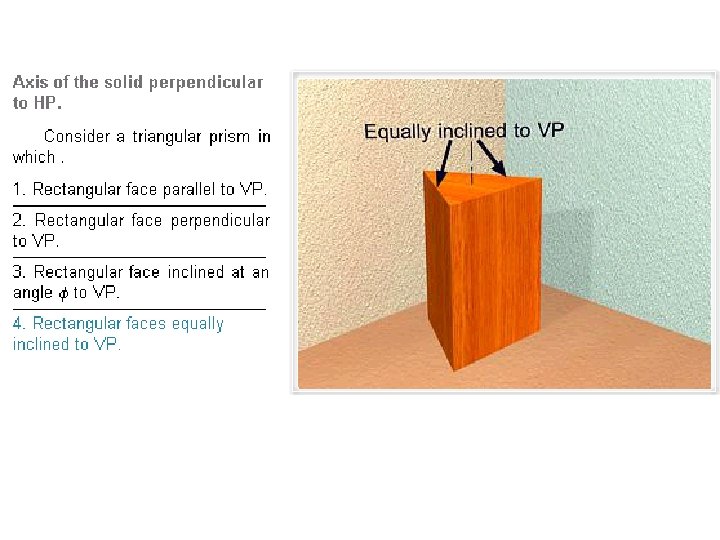
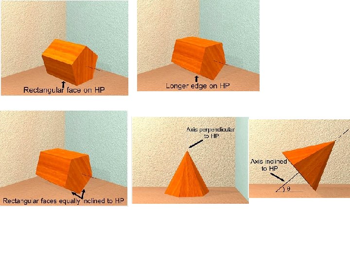
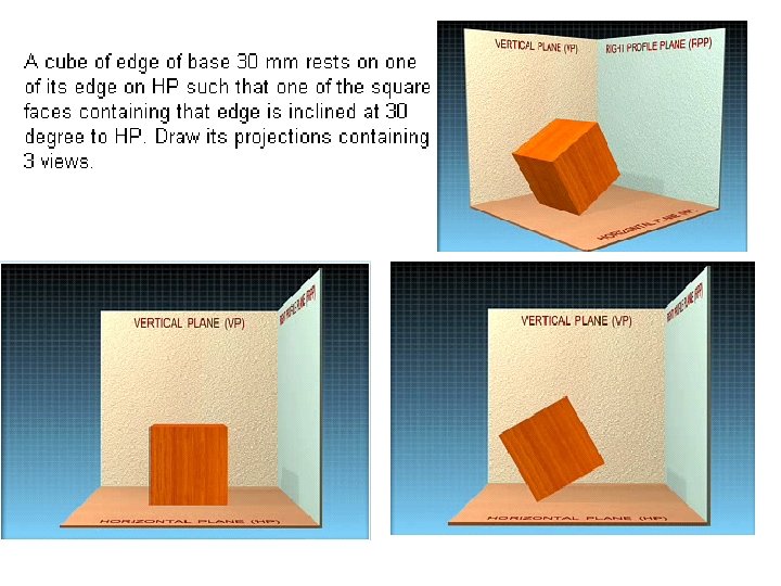
Projection of Solids • What is solid: – A solid may be defined as a three dimensional object having length, breadth and thickness bonded by surfaces. Solids may be classified under two headings 1. Polyhedron 2. Solids of revolution