Computer Aided Engineering Drawing Lecture Four CAD CAD


![Menu bar with Modify-Offset and: prompt Specify offset distance or [Through]<37. 5> enter 50](https://slidetodoc.com/presentation_image/354fc596f600bfa161c1caa2036804c1/image-8.jpg "Menu bar with Modify-Offset and: prompt Specify offset distance or [Through]<37. 5> enter 50")


- Slides: 18
Computer Aided Engineering Drawing ﺍﻟﺮﺳﻢ ﺍﻟﻬﻨﺪﺳﻲ ﺍﻟﻤﻌﺎﻥ ﺑﺎﻟﺤﺎﺳﻮﺏ Lecture Four CAD / CAD Engineering Dr. Tahseen Fadhil Abbas 2012 -2013
The offset , extend , trim and change commands In this lecture we will investigate OFFSET, EXTEND and TRIM three of the most commonly used draughting commands. We will also investigate how an object’s properties can be altered with the CHANGE command.
Offset The offset command allows to user to draw objects parallel to other selected objects and lines, circles and arcs can all be offset. The user specifies: • an offset distance • the side to offset the selected object.
Inclass. Ex 4
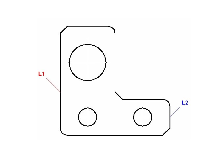
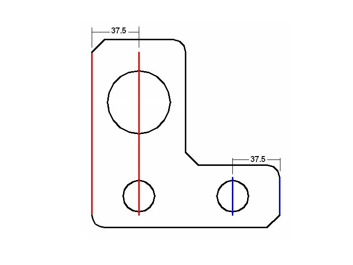
Refer to Fig. Pick the OFFSET icon from the Modify toolbar and: prompt Specify offset distance or [Through] enter 37. 5 <R> – the offset distance prompt Select object to offset or <exit> respond pick line L 1 prompt Specify point on side to offset respond pick any point to right of line L 1 as indicated and line L 1 will be offset by 37. 5 units to right prompt Select object to offset, i. e. any more 37. 5 offsets respond pick line L 2 prompt Specify a point on side to offset respond pick any point to left of line L 2 as indicated and line L 2 will be offset 37. 5 units to left prompt Select object to offset, i. e. any more 37. 5 offsets respond right-click to end command.
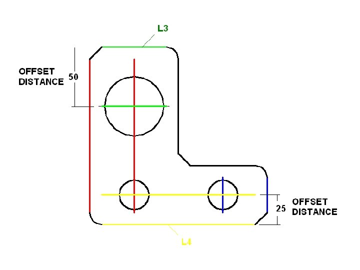
Menu bar with Modify-Offset and: prompt Specify offset distance or [Through]<37. 5> enter 50 <R> prompt Select object to offset and pick line L 3 prompt Specify a point on side to offset and pick as indicated. 4 At the command line enter OFFSET <R> and: a) set an offset distance of 25 b) offset line L 4 as indicated.
EXTEND This command will extend an object ‘to a boundary edge’, the user specifying: a) the actual boundary – an object b) the object which has to be extended. •
OFFSET Refer to Fig. and OFFSET the three circles for a distance of 5 ‘outwards’
TRIM Allows the user to trim an object ‘at a cutting edge’, the user specifying: a) the cutting edge – an object b) the object to be trimmed.
ERASE
Changing the offset centre lines The DWG was saved with ‘centre lines’ obtained using the Offset, Extend and trim commands. These lines pass through the three circle centres , but they are continuous lines and not centre lines. We will modify these lines to be centre lines using the CHANGE command. This command will be fully investigated in a later lecture, but for now: CHANGE
At the command line enter CHANGE <R> and: prompt Select objects respond pick the six offset centre lines then right-click prompt Specify change point or [Properties] enter P <R> – the properties option prompt Enter property to change [Color/Elev/LAyer/LType/ lt. Scale/LWeight/Thickness] enter LT <R> – enter CENTER <R>
Save as : Inclass. Ex 6
H. W. 3
THANK YOU