Computed Tomography CT COMPUTED TOMOGRAPHY is well accepted
 • • • COMPUTED TOMOGRAPHY is well accepted imaging modality for")


 is the linear attenuation coefficient at each point in the x-ray")


- Slides: 24
Computed Tomography (CT) • • • COMPUTED TOMOGRAPHY is well accepted imaging modality for evaluation of the entire body. The images are obtained directly in the axial plane of varying tissue thickness with the help of a computer. Some pathology can be seen in sagittal or coronal plane by reconstruction of the images by computer. CT has undergone several evolutions & now the days multi-detectors CT scanners have been evolved which have application in the clinical field.
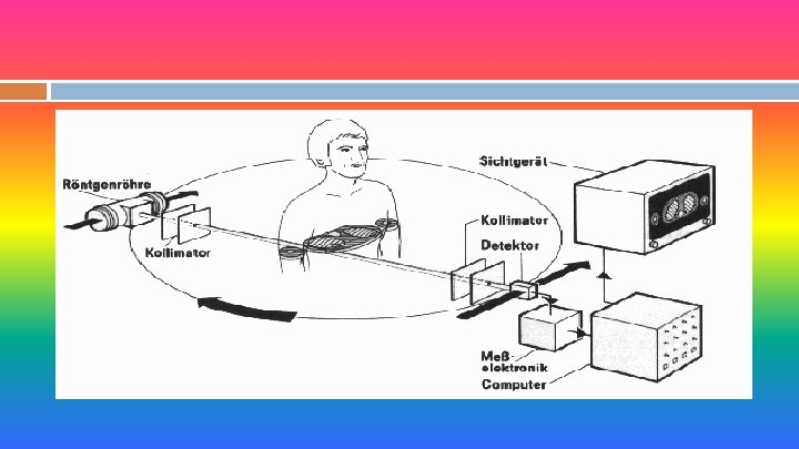
Basic Principle The basic principle behind the CT is that the internal structure of an object can be reconstructed from multiple projections of the object. The projections are formed by scanning a thin cross section of the body with a narrow x-ray beam and measuring the transmitted radiation with a sensitive radiation detector. The detector does not form the image. It merely adds up the energy of all the transmitted photons.
Data Accumulation Data-gathering techniques have developed by stages. The number of ray projections increases from 28800 in the original scanner to more than one million in newer scanners. Image quality is related to the number of ray projections used to reconstruct each CT scan image.
Original EMI Scanner The original EMI scanner was designed specifically for evaluation of the brain. It consists of an x-ray tube and pair of detectors below. A third, a reference detector, intercepted a portion of the beam before it reached the patient. The x-ray beam was collimated to the exact size of the two side by side detectors.
Original EMI Scanner
Original EMI Scanner The gantry of the scanner moved through two different types of motion while the patient remains in one position. 1 - Linear motion, repeated over 180 times. 2 - rotary motion, the gantry rotated 1° step in a semicircle of 180°. The axis of rotation pass’ through the center of the patient’s head.
Original EMI Scanner The transmitted radiation is measured 160 times in each linear movement. The total number of measurements in each linear movement is the product of 160 x 180 =28800. In the EMI scanner, the CT image is reconstructed and then displayed on an 80 x 80 matrix in two different formats 1 - Paper printout of CT numbers. 2 - Visual image on a cathode ray tube (monitor).
Original EMI Scanner Each square in the image matrix is called a pixel, and it represents a tiny elongated block of tissue called a voxel. The total scan time is between 4. 5 and 5 minutes.
Original EMI Scanner
Scanning Motions CT scanners have gone through a number of design changes since the technology was first introduceed in 1971. 1 - First Generation (translate-rotate, one detector). 2 - Second Generation (translate-rotate, multi detectors). 3 - Third Generation (rotate-rotate). 4 - Fourth Generation (rotate-fixed).
X-Ray Tube The radiation source for CT would supply a monochromatic x-ray beam (one made up of photons all having the same wavelength). Monochromatic beam makes the reconstruction of image simpler and more accurate. New fan beam units have a diagnostic-type x-ray tube with a rotating anode and a much smaller focal spot. In some units down to 0. 6 mm.
Collimators The x-ray beam is collimate at two points, one close to the x -ray tube and the other at the detector(s). Perfect alignment between the two collimators is essential. The collimator at the detector is the sole means of controlling scatter radiation. Each detector has its own collimator. The collimators regulate thickness of the Tomographic slice (voxel length).
Detectors There are two types of detectors used in CT scanners. 1 - Scintillation crystal. Used in rotate-fixed type scanner and although may used in rotate-rotate type scanner. 2 - Xenon gas ionization chambers. Limited in use to rotate-rotate (Third generation) type scanner.
Scintillation crystals They are any of an extremely large number of materials, these materials are those that will produce light(scintillate) when ionizing radiation reacts with them. On a single interaction of a photon with a crystal the energy of the x-ray photon will be converted to light photons, with the number of light photons proportional to the energy of the incident x-ray photon.
Scintillation crystals All crystals must be matched to a light detector to convert the light output to an electrical signal. The combination of scintillation crystal and the light detector is called the scintillation detector.
Xenon gas ionization chambers. In all Xenon gas detectors there must be 1. An Anode and a cathode. 2. A counting gas (inert gas). 3. A voltage between the anode and cathode. 4. Walls that separate the detector from the rest of the world. 5. A window for the radiation photon to enter the detector.
Xenon gas ionization chambers. Gas detectors come in a variety of sizes and shapes. Usually a size and shape is selected for a particular application. All gas-filled detectors use ionization of the gas by the incoming radiation to produce a signal. The x-ray photon interacts with a gas atom by ionizing the atom into an electron-ion pair.
Xenon gas ionization chambers. The voltage between the anode and cathode will cause the electron to move toward the anode and the positive ions toward the cathode. When electron reach the anode, they produce a small current in the anode, this current is the signal. For low voltage, only the negative ions produced by the photon are collected by the anode. The current is directly proportional to the intensity of the incoming radiation.
CT Scan Methodology v v v X-ray tube and detectors rotate around the patient, with the axis of rotation running from the patient’s head to toe Detectors measure the average linear attenuation coefficient, µ, between the tube and detectors Attenuation coefficient reflects the degree to which the X-ray intensity is reduced by the material it passes through 2 D measurement are taken in a helical manner all around the patient Attenuated data is summed up from thousands of angles used in a process called reconstruction Contrast dye is sometimes used to make the internal organs more visible in the image
CT-Physics CT scanning depends on the x-ray attenuation. Where Io is the intensity of the incident beam, I is the intensity of the beam after passing through a thickness x, and µ is the linear attenuation coefficient of the material. For a non homogeneous medium
CT-Physics Where µ(s) is the linear attenuation coefficient at each point in the x-ray track. The last equation can be written as
Each square in the image matrix was called a pixel, And it represent a tiny elongated block of tissue Called a voxel. The size of pixel was determined by the computer Program and not by the dimensions of x-ray beam.
Conventional Tomography Blurring Image produced on film Objects above or below fulcrum plane change position on film & thus blur