COMPONENTS OF CARDIAC PACEMAKER AND ITS REQUIREMENT ZAINAB

COMPONENTS OF CARDIAC PACEMAKER AND ITS REQUIREMENT ZAINAB BT DIN IYLIA AMIEZA BT IDRIS HUSNA ATIRAH BT HUSSIN NOOR ALBATYIAH BT NORDIN NUR HAMIZAH BT KAMAL AZLAN

PACEMAKER COMPONENT

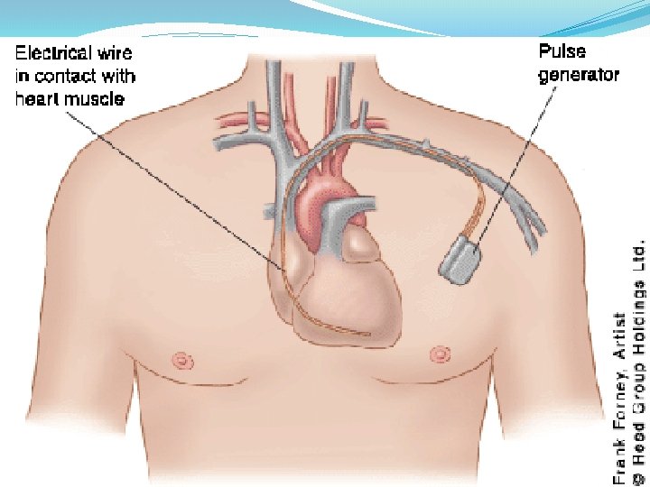
INTRODUCTION �A pacemaker system is a device capable of generating artificial pacing impulses and delivering them to the heart. �Cardiac pacemaker is an electric simulator that produces periodic electric pulses that are conducted to electrodes located on the surface of the heart, within the heart or within the cavity of the heart or the lining of the heart. �External electrical simulation impulses to the heart muscle – to regulate the heart rate.

Why we use pacemaker? �If sino-atrial node ceases to function or becomes unreliable or if the triggering pulses does not reach the heart muscle because of blocking by the damaged tissue, the natural synchronization of the heart action gets disturbed.

Asynchronous Cardiac Pacemaker Components �Electronic Circuitry �Packaging �Power source �Lead system �Electrode

BLOCK DIAGRAM OF AN ASYNCHRONOUS CARDIAC PACEMAKER POWER SUPPLY OSCILLATOR PULSE GENERATOR PULSE OTPUT CIRCUIT LEAD WIRES ELECTRODES

Electronic circuitry �The circuit is designed so that the batteries supply sufficient power for a long period �Requirement for the circuit are: � The component should be highly reliable � The power source should be in a position to supply sufficient power to the circuit over a long period � The circuit should be covered by the biological inert material – biocompatible � The unit should be covered in such a way that the body fluids do not find a way inside the circuit

Packaging �The cardiac pacemakers now are packaged in hermetically sealed metal packages. �Titanium & stainless steel are frequently used for the package thus providing complete & enduring isolation from the corrosive body environment. �Special electron beam or laser welding techniques have been developed to seal these packages without damaging the electronic circuit or the power source. �These metal packages take up less volume and are more reliable than the earlier, polymer-based packages.

Power source �The hub of the pacemaker and consists of a sealed lithium - iodine battery �Responsible for producing the electrical signals that cause the heart to beat. �Advantages: �Long life – 4 to 10 years �Output voltage decreases gradually with time making sudden battery failure unlikely

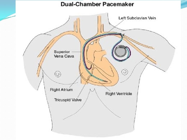
Lead Wires �Insulated, flexible wires that carry the electrical signals from the pulse generator to the heart. �Two types of lead : 1. Unipolar � A single electrode in contact with the heart, & negative-going pulses are connected to it from the generator 2. Bipolar � Two electrodes are placed within or on the heart & the stimulus is applied across these electrodes.

�Requirement for the lead wires � Must be a good electrical conductors � Mechanically strong – able to withstand the stress of being flexed in various positions. � Must be a good electrical insulation �To meet these requirement, the lead wires used consist of interwound helical coils of spring-wire alloy molded in a silicon-rubber or polyurethane cylinder. �Helical coiling of wire minimizes stresses applied to it �The silicon-rubber en capsulation both maintain flexibility and provides electrical insulation and biological compatibility

Electrode Ø Requirement for electrodes � Must be able to withstand repeated stress & must remain in place to provide effective pacing. � The materials must not dissolve during long-term implantation, cause undue irritation to the heart tissue adjacent to them, or undergo electrolytic reactions when the stimulus is applied.

Materials for electrodes and lead wires Ø Titanium � High modulus of elasticity. � High resistance to corrosion. � High durability. Ø Platinum-iridium � Stronger than most steels. � Used in steroid-eluting leads. Ø May be coated with iridium oxide � Prevents nonconductive layers from forming. � Reduces local inflammation.

SYNCHRONOUS PACEMAKER �Some cases, continuous stimulation can even result in serious complication. �Artificial pacemaker must not compete with the normal heart’s normal pacing action. �Two general forms of synchronous pacemakers. � The demand pacemaker � Atrial-synchronous pacemaker

Demand-type Synchronous Pacemakers Timing circuit Reset circuit Output circuit Electrodes Amplifier A demand-type synchronous pacemaker – Electrodes serve as a means of both applying the stimulus pulse and detecting the electric signal from spontaneously occurring ventricular contractions that are used to inhibit the pacemaker’s timing circuit

Demand-type Synchronous Pacemakers �The timing circuit is set to run at a fixed rate, usually 60 to 80 beats/min. �After each stimulus, the timing circuit reset itself, waits the appropriate interval to provide next stimulus and then generates the next pulse. �If during this interval a natural beat occurs, the feedback circuit detects the QRS complex of ECG signal from the electrode and amplifies it. �This signal is used to reset the timing circuit. 18

Demand-type Synchronous Pacemakers �If the heart beats again before the stimulus is produced, the timing circuit is again reset and the process repeat itself. �When the heart conduction system is operating normally and the heart has a natural heart rate that is greater than the rate set for the timing circuit, the pacemaker remain on standby mode and the heart operates under its own pacing control. 19

Atrial-Synchronous Pacemakers Atrial electrode v 1 Amplififer Gate Monostable multivibrator 120 -ms delay v 2 Monostable multivibrator 2 ms v 3 v 4 Monostable multivibrator 500 -ms delay Output circuit Ventricular electrode An atrial-synchronous cardiac pacemaker, which detects electric signals corresponding to the contraction of the atria and uses appropriate delays to activate a stimulus pulse to the ventricles. 20

Atrial-Synchronous Pacemakers �Designed to replace the blocked conduction system of the heart �SA node stimulate the atria, the electric signal is detected by an electrode implanted in the atrium & use to trigger the pacemaker the same way it triggers the AV node �The atrial signal is amplified & passed through a gate to a monostable multivibrator (MM) giving a pulse v 2 of 120 -ms duration (the ~ delay of the AV node) �Another MM, 500 -ms produces v 4 which causes the gate to block any signals from the atrial electrodes �The pacemaker is refractory to any additional stimulation for 500 -ms 21

Atrial-Synchronous Pacemakers �v 2 is used to trigger a MM of 2 -ms duration �The pulse v 2 acts as a delay, allowing the ventricular stimulus pulse v 3 to be produced 120 ms following atrial contraction �v 3 controls an output circuit that applies the stimulus to appropriate ventricular electrodes 22

Conclusions �Pacemakers are becoming more common everyday �We need to understand basic pacing terminology and modes to treat patients effectively. �Most pacer malfunctions are due to failure to sense, failure to capture, over-sensing, or inappropriate rate
- Slides: 23